
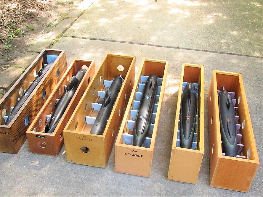
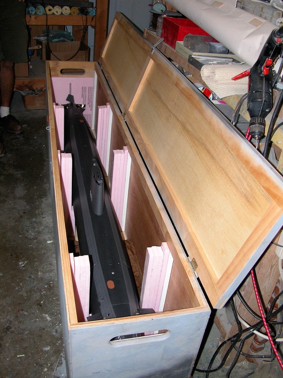
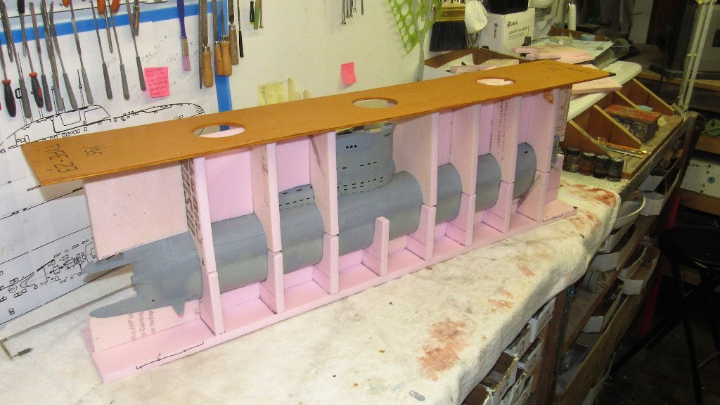
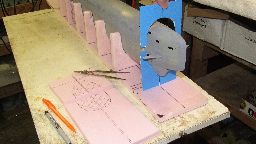
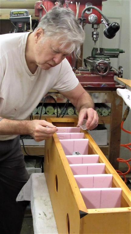
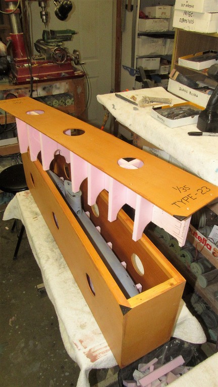
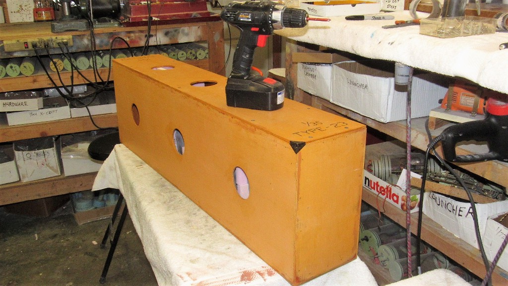
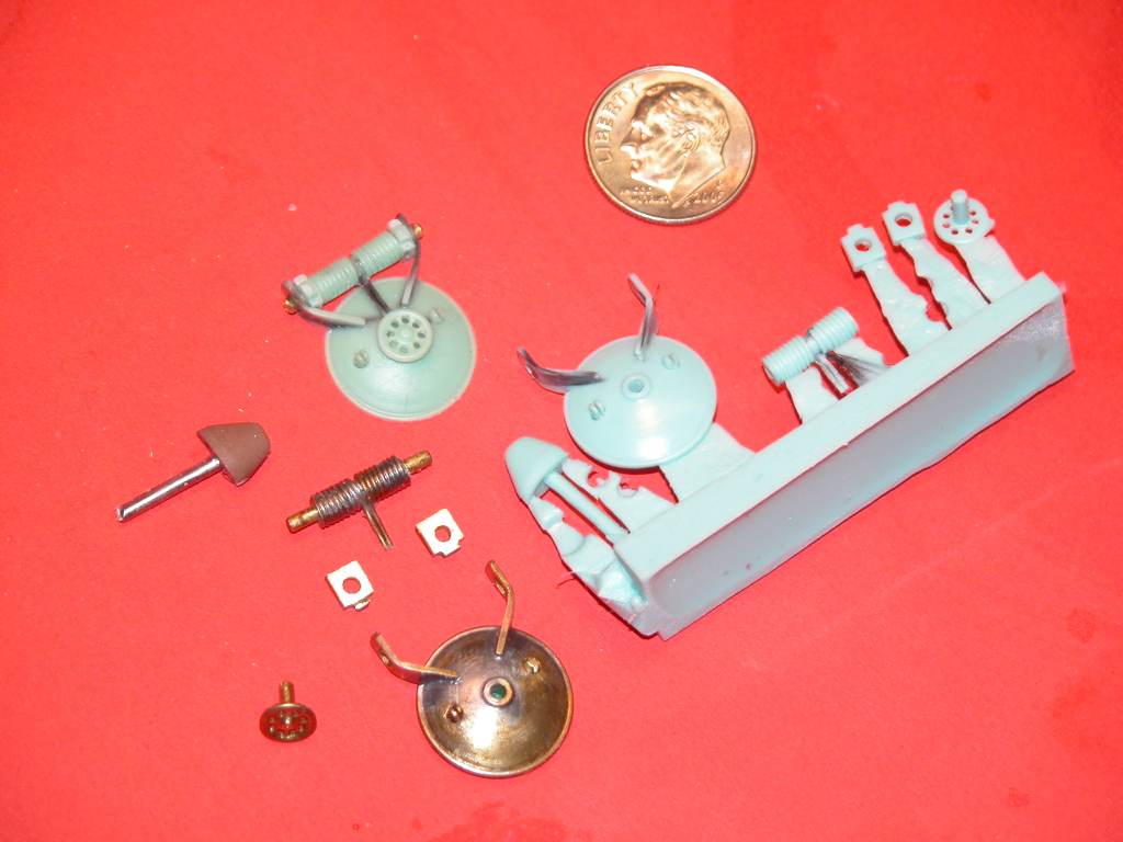
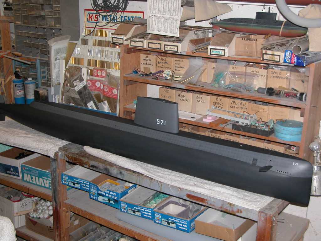
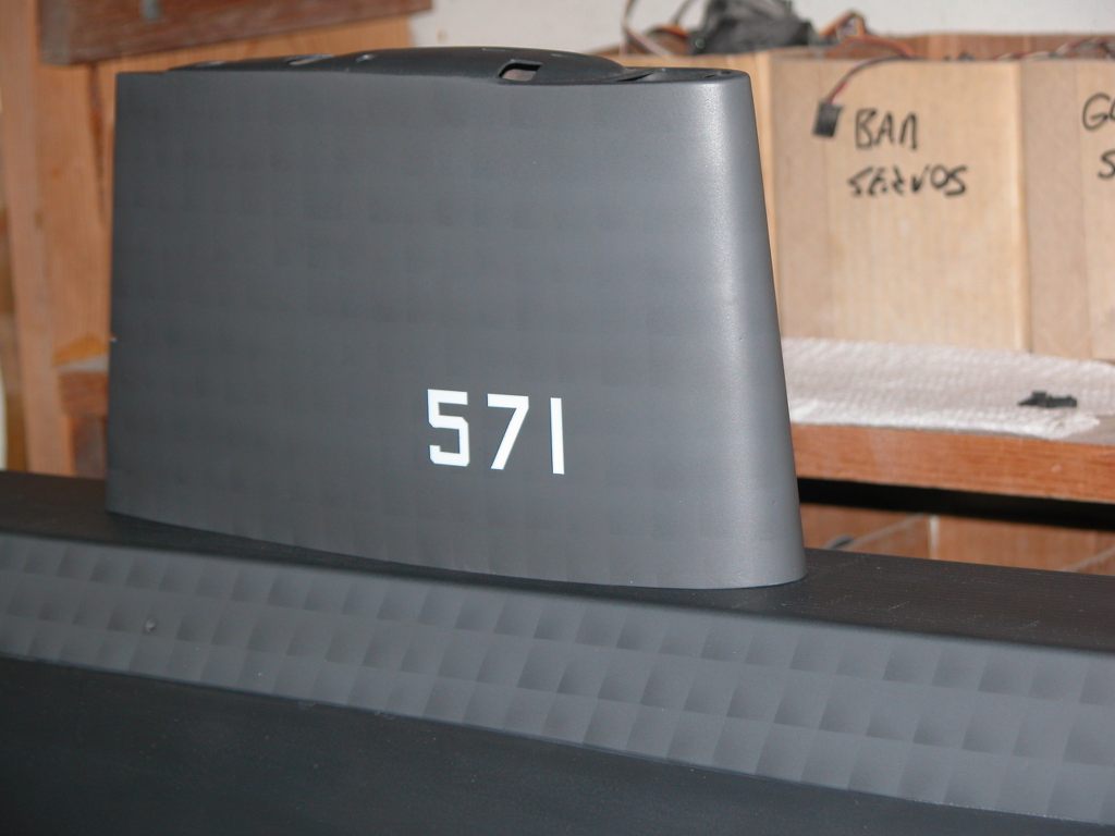
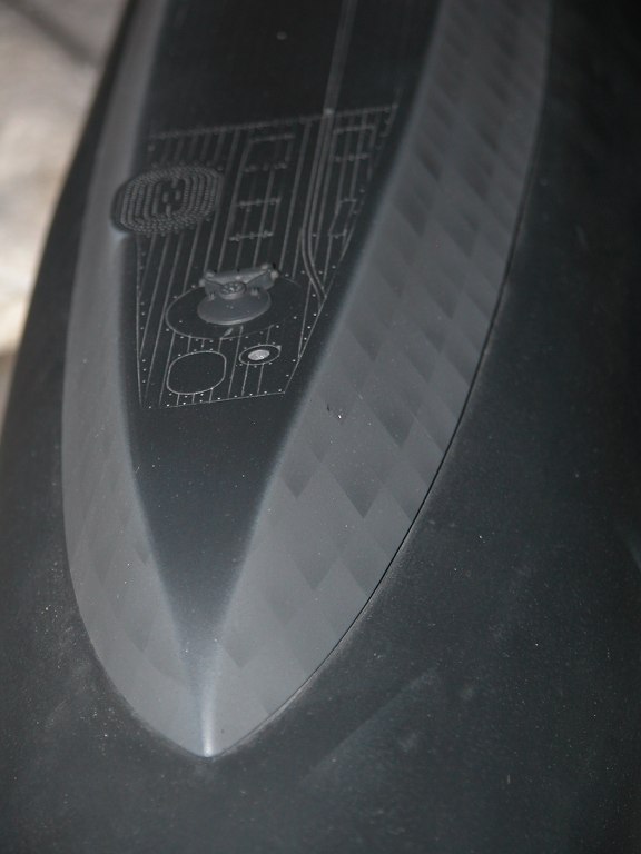
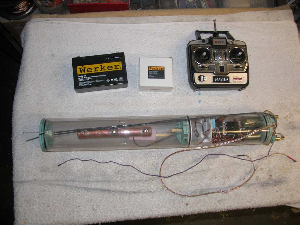
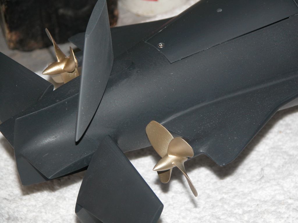
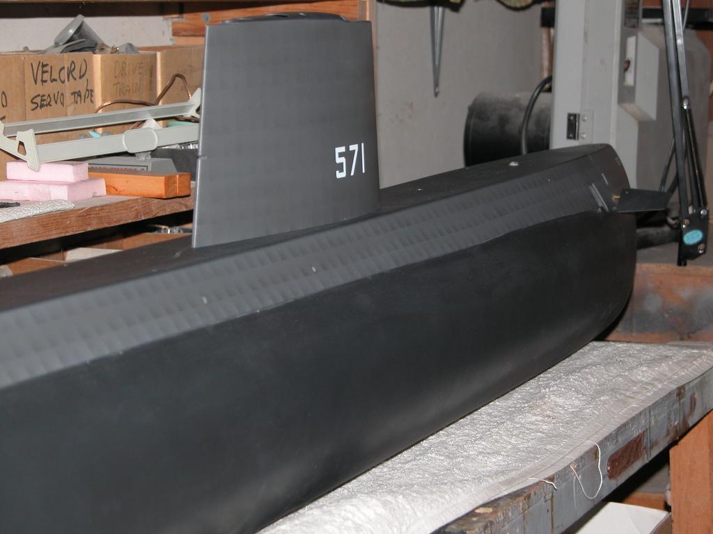
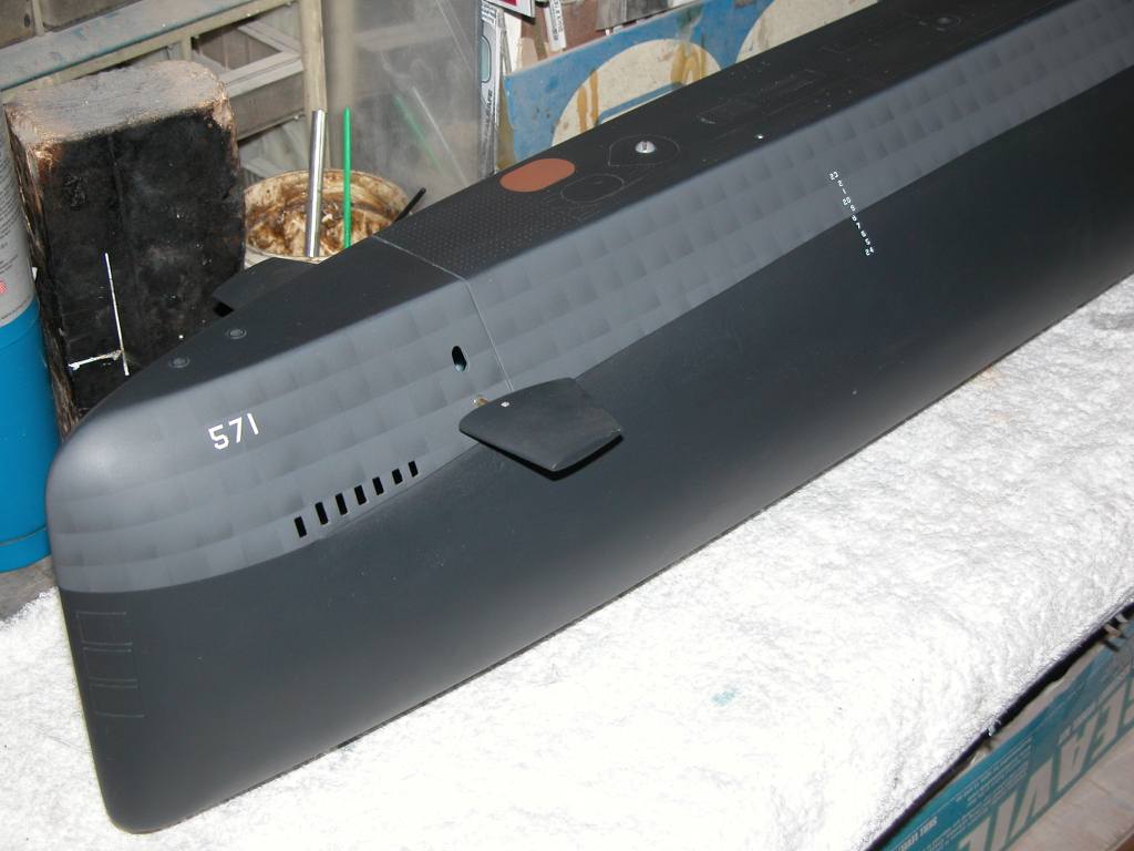
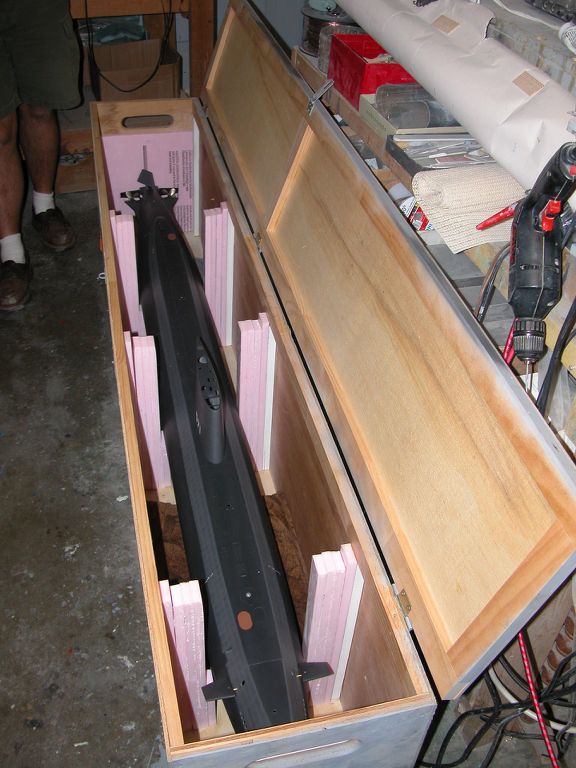
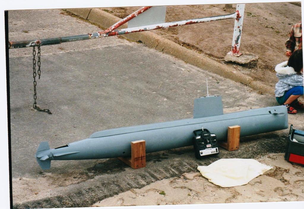
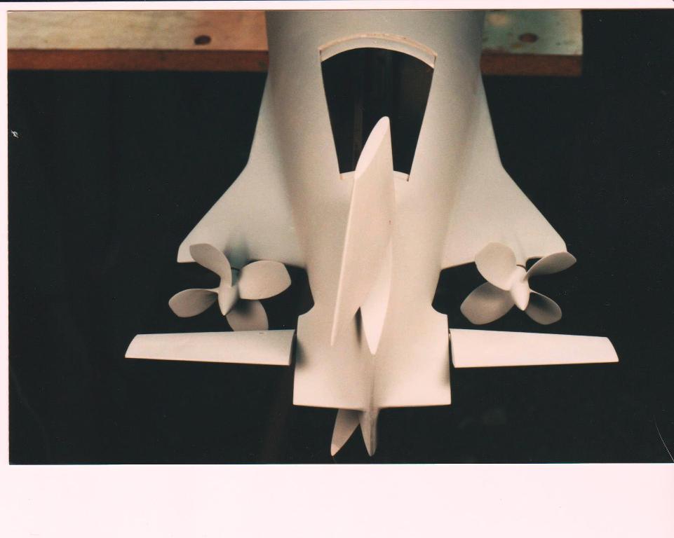
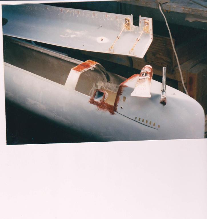
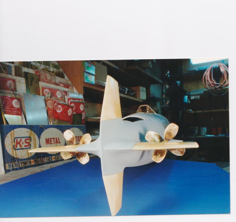
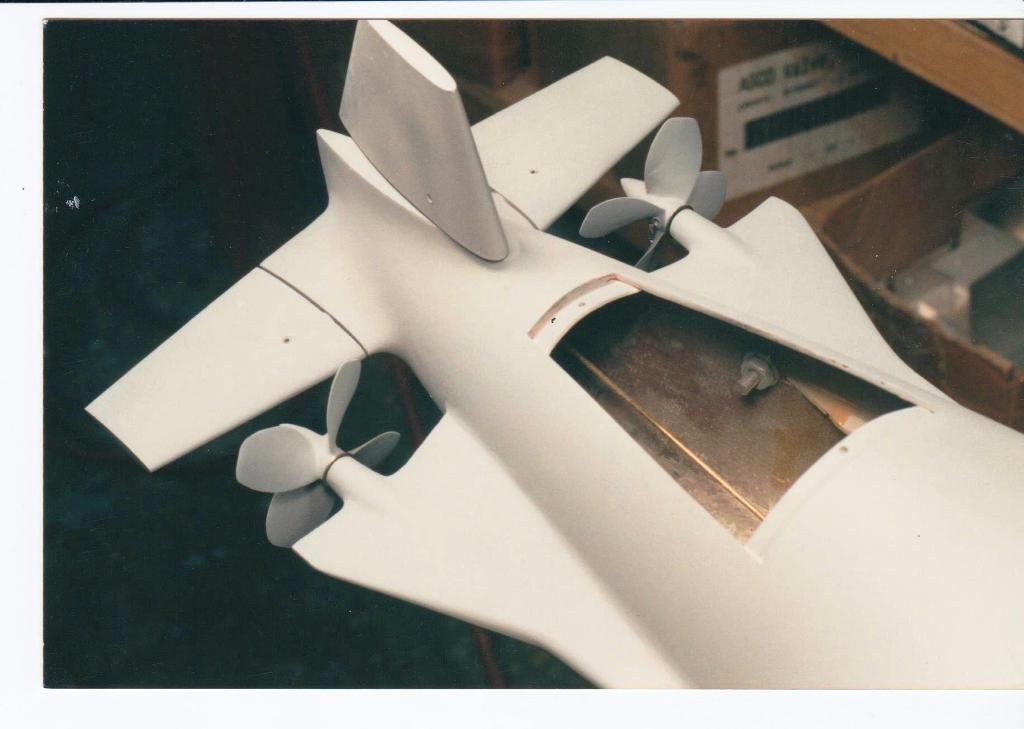
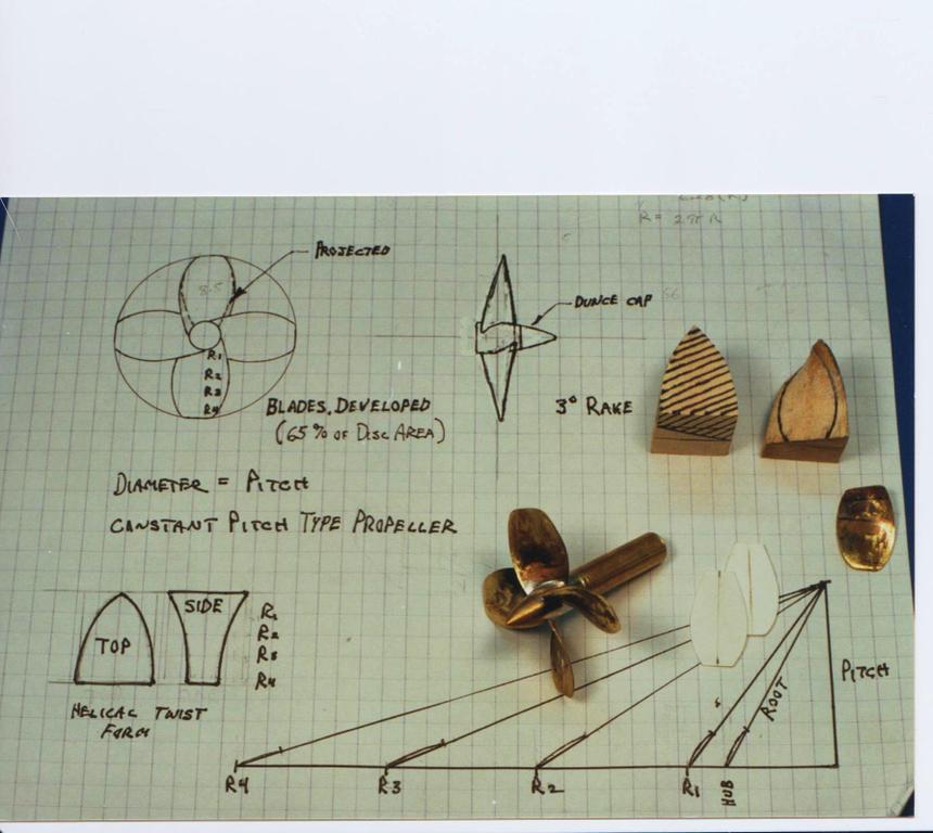
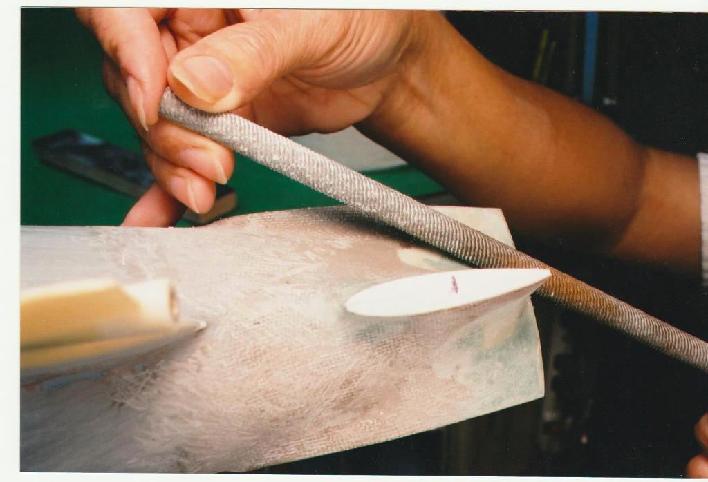
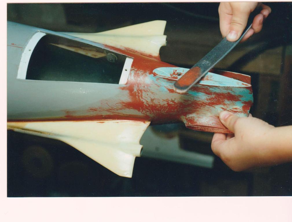
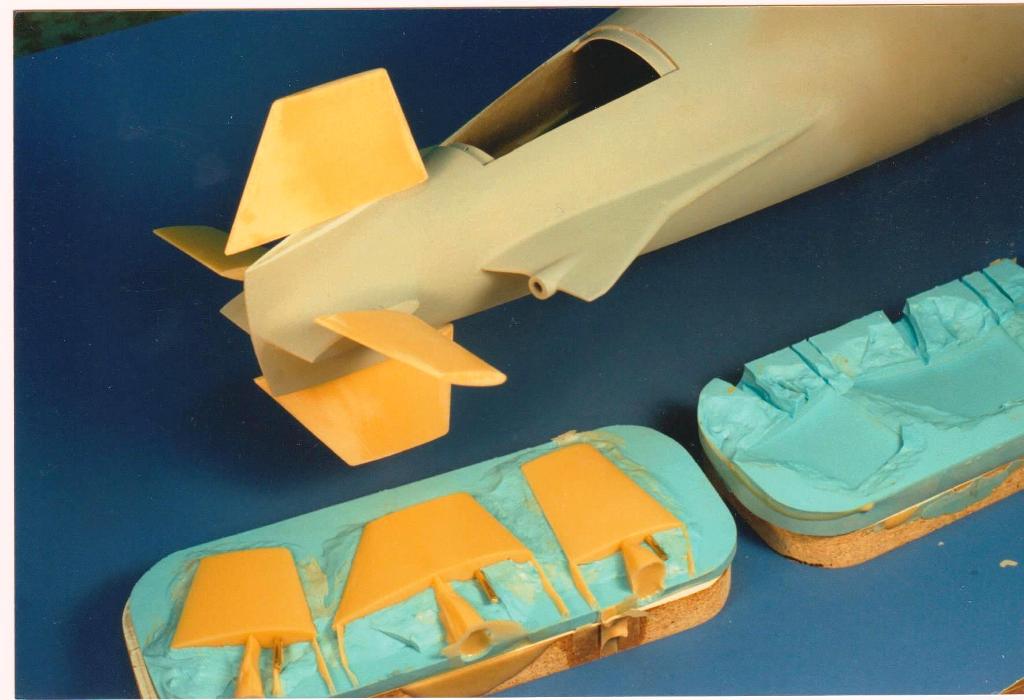
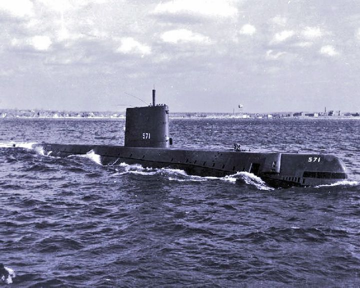
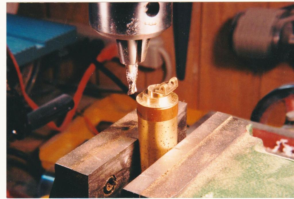
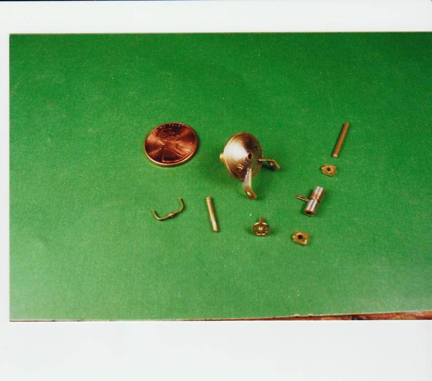
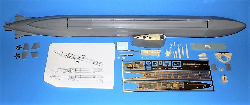
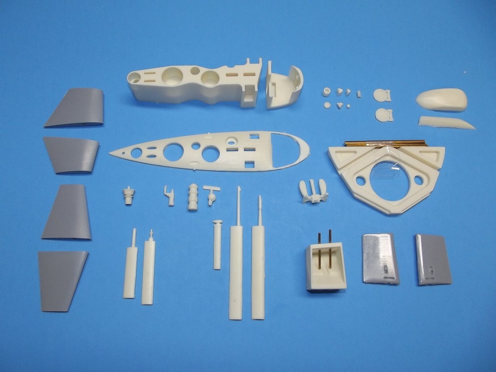
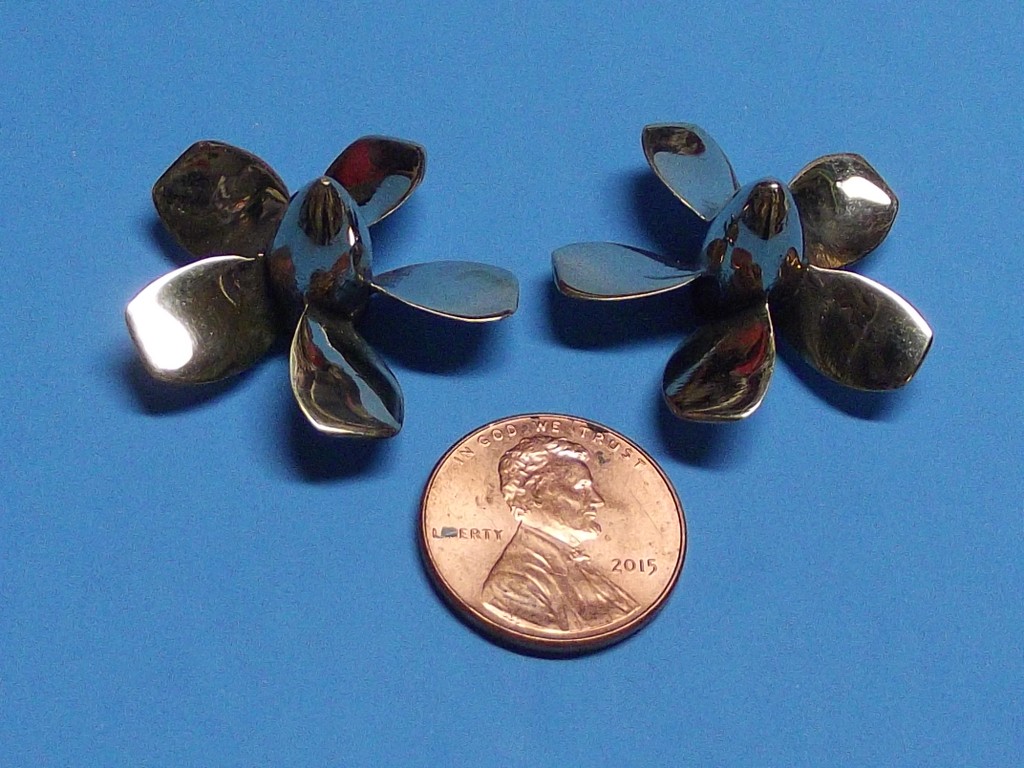
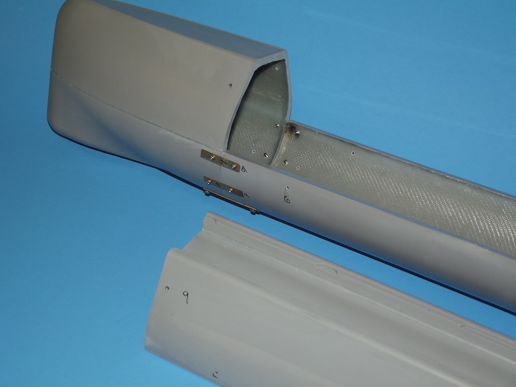
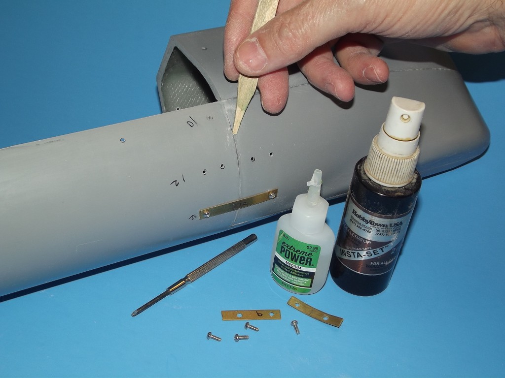
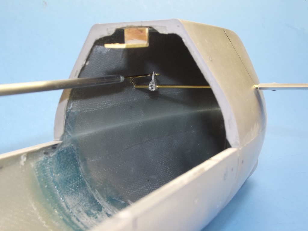
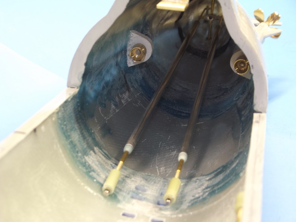
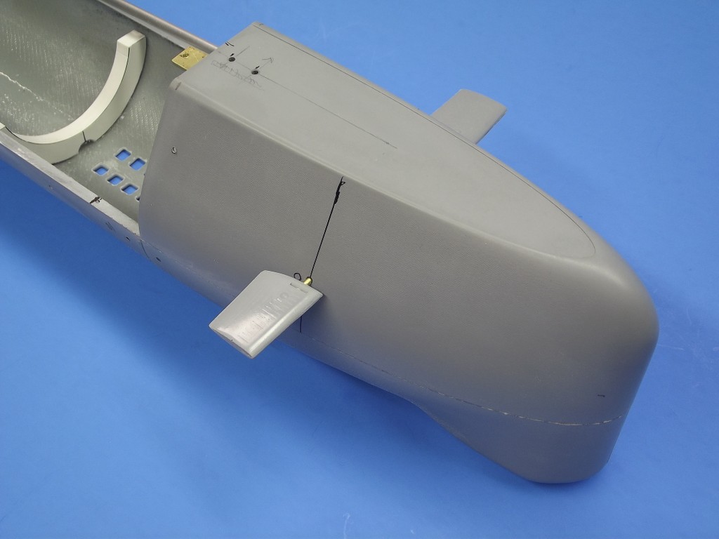
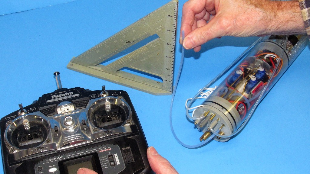
It has been a long time, since I’ve logged in on the forum.. I was surprised to see a Bronco XXIII currently under construction! I remember the development of the fitting kit in Spring 2013. And more specifically the propeller. I still have my two Bronco kits and the fitting kits for them. After hearing about the latest new Sub Drivers, from Bob’s emails, I’m curious to see the new 2.5” Driver that will fit this model.
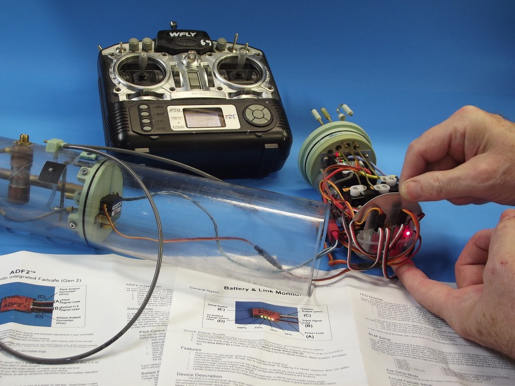
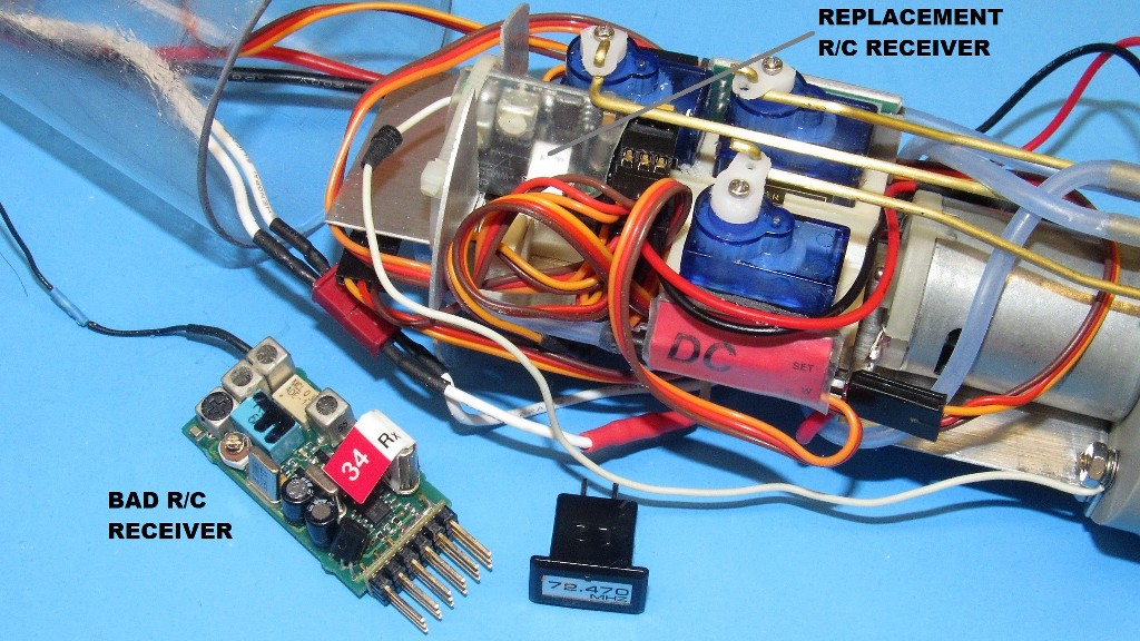
As I recall, David had a pitch control problem with the XXIII he used to develop the kits with. Was that problem ever solved?
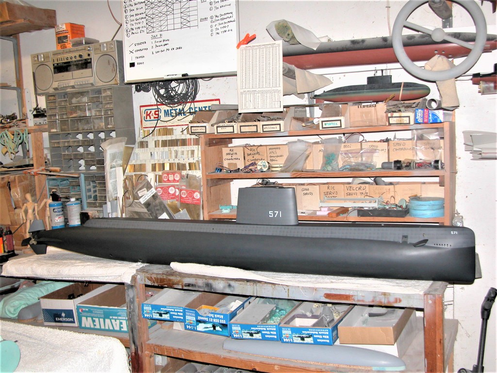
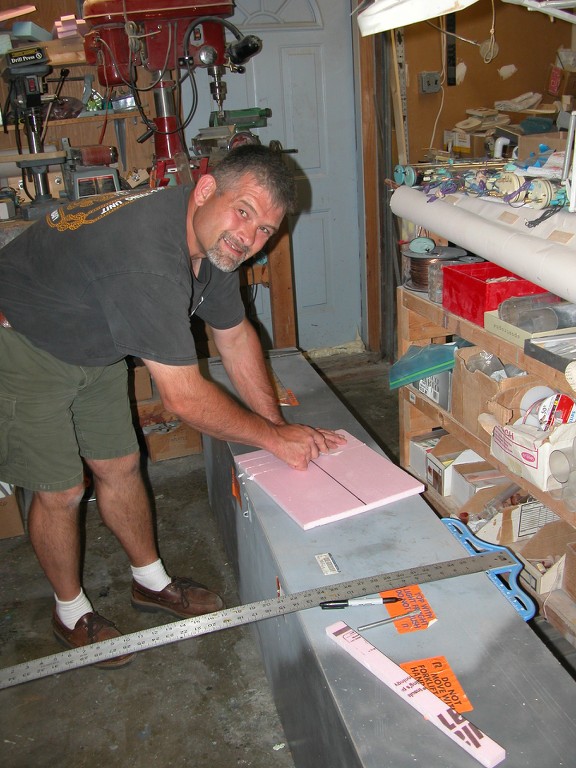
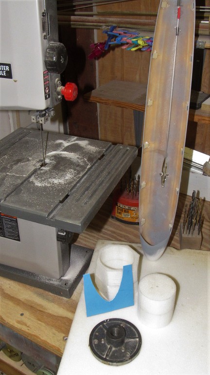
Over the last two years, I’ve been fixing / restoring an old Dodge Charger Super Bee, as time has allowed. When I’m finished with that big project, I’d like to do some work on my XXIII models. It will be nice to work on something I don’t have to crawl under for a change.
As I recall, David had a pitch control problem with the XXIII he used to develop the kits with. Was that problem ever solved?
Over the last two years, I’ve been fixing / restoring an old Dodge Charger Super Bee, as time has allowed. When I’m finished with that big project, I’d like to do some work on my XXIII models. It will be nice to work on something I don’t have to crawl under for a change.


Comment