today's work

Collapse
X
 
  • Time
  • Show
Clear All
new posts
  • mike27283
    Lieutenant, Junior Grade
    • Aug 2020
    • 18

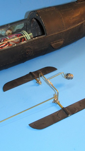
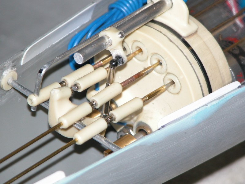
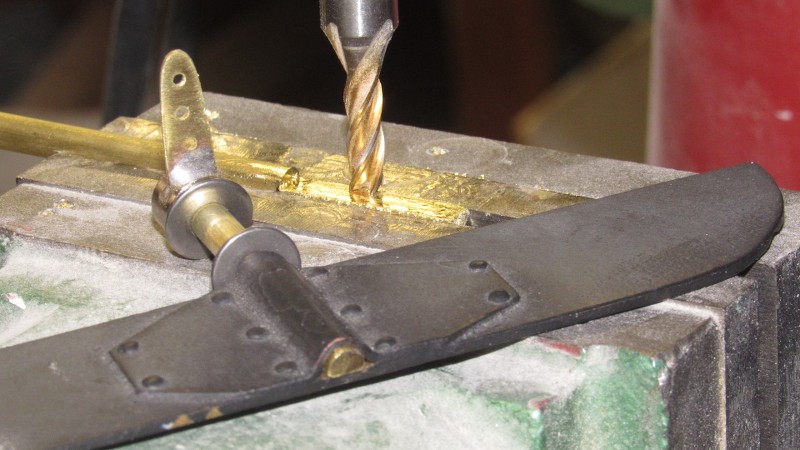
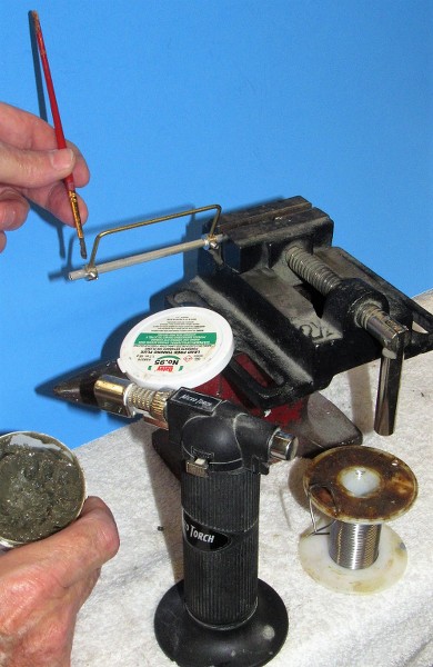
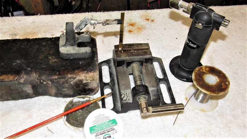
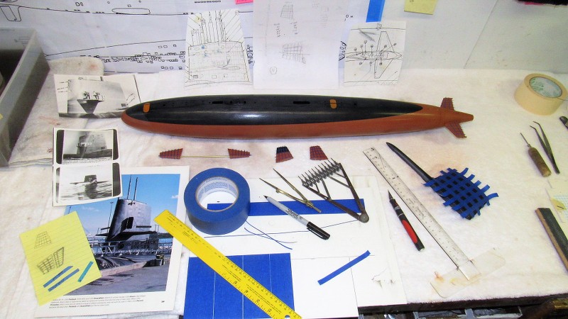
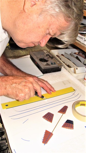
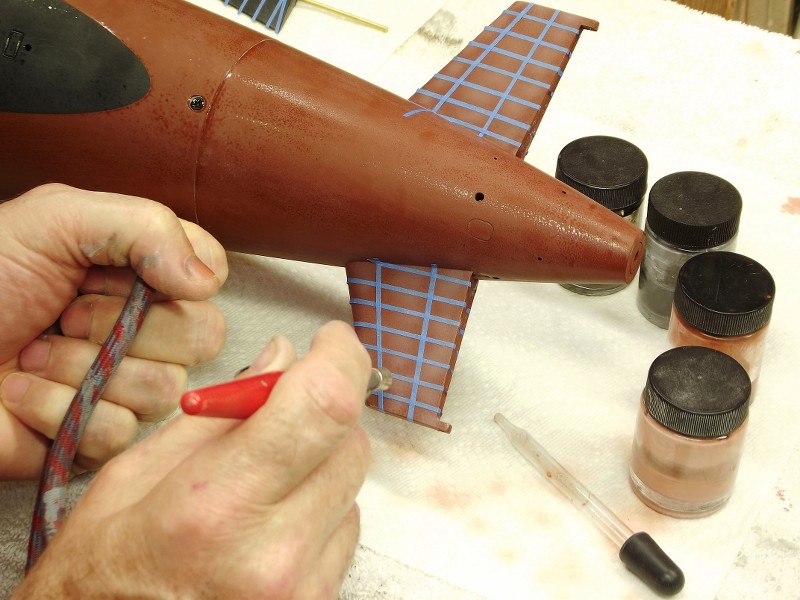
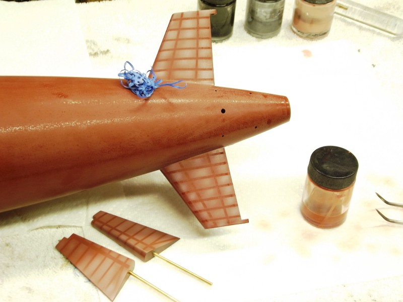
    Some build pics for those interested... Glad to share the code for the BS2 and discuss. Please excuse the quality of photos, order and such - was not planning on posting when I took these.

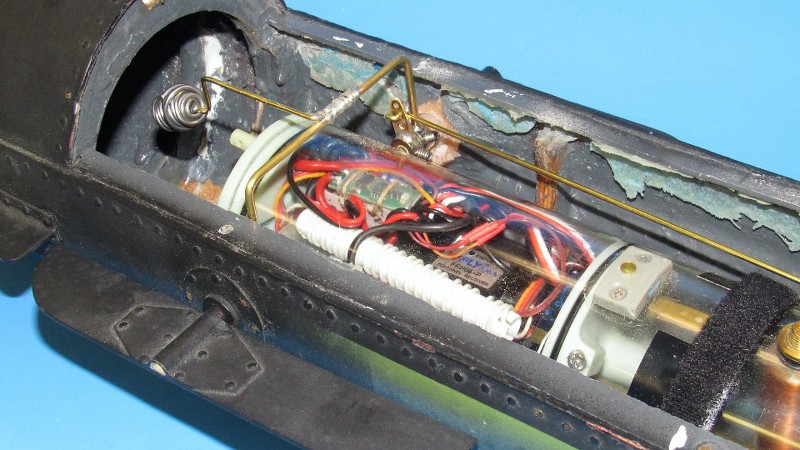
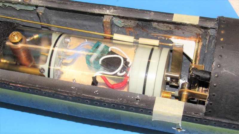
    Originally started with a screw motor but switched to the linear servo - hence the schematic is not updated as the H-circuit to drive the motor is no longer required. Also switched radio / receiver, upgraded to metal servos, battled connector and radio issues...all operational now. Once the mast mechanism is in place I'll start to see the light at the end of the tunnel. But - as we all know - hopefully it's not the oncoming train!
    Attached Files

    Comment

    • mike27283
      Lieutenant, Junior Grade
      • Aug 2020
      • 18

      Final post for today...my fathers old coffee cup from the USS Scorpion. As you can imagine - this has a lot of sentimental value to me...
      Attached Files

      Comment

      • trout
        Admiral
        • Jul 2011
        • 3545

        Is your ballast tank going to be that far rearwards?
        If you can cut, drill, saw, hit things and swear a lot, you're well on the way to building a working model sub.

        Comment

        • mike27283
          Lieutenant, Junior Grade
          • Aug 2020
          • 18

          Trout - yes. The CG when dry is in the center of the boat longitudinally. The forward and aft WTC’s are not symmetrical…the forward is longer than the aft. Will the buoyancy of the larger forward WTC counteract the lifting and imparted rotation bow down when the ballast tank is pumped with air…? When I finally get this thing wet and start working on trimming it I am hoping so… By my calculations the ballast tank will not need to be completely dry to force the boat up to the waterline. That also reduces the force of the imparted rotation. But I am a newbie and this may be another issue Ill have to work through. What are your thoughts based on your experience?

          Comment

          • He Who Shall Not Be Named
            Moderator
            • Aug 2008
            • 12253


            With the linkages for the pitching propeller and rudder worked out in head and on paper, things moved to manufacture, installation and... after the usual bumps in the road... successful operation. The rudder would wag, and the propeller would pitch up and down.

            The bow planes.

            Time had come to work out a practical linkage to connect the outrageously heavy HUNLEY bow planes to the WTC's bow plane servo.

            Here's the end-game of the work required to interconnect the two bow planes. That U-shaped item between the planes is a 'yoke', needed to achieve clearance over the installed WTC. The inclusion of that WTC negated the ability to run a simple, one-piece bow plane operating shaft between the planes.

            Nothing's EVER simple or easy!


            The control horns used to rotate the control surface operating shafts were made from DuBro wheel-collars soldered to strips of brass sheet. A finished horn attached to its operating shaft of the bow plane on the right, parts of a soon to be assembled control horn next to the bow plane on the left. Note the flat milled to the end of the operating shaft that fits the bow plane.

            This shot also denotes the three means of active control of the r/c model HUNLEY: The pitching propeller, used to vary and maintain the pitch-angle of the submerged submarine; the linkage used to swing the rudder for yaw control; and the means of rotating the bow planes to make fine adjustments to the submarines depth when running submerged.


            Initially I planned to put a control horn to each bow plane operating shaft but found that it would be easier to run a yoke between them rather than employing a two-legged pushrod (with each leg engaging an operating shaft control horn). As the eventual yoke carried both operating shafts, I needed only one horn and one push rod. KISS! (Keep It Simple, Stupid!).


            The WTC's servo pushrods terminated in magnets which matched up to corresponding magnets that continued the linkages to the mechanisms that swung the rudder and pitched the propeller. Here is a look at the magnets and how they were secured to the push rods and bell-cranks.

            The example to the right is a completed magnet assembly secured to a length of 1/16" diameter brass rod -- the same type rod that passes through the WTC's watertight seal. Note that the position of the magnet on the rod can be adjusted by simply loosening a set-screw, repositioning the magnet along the length of the push rod, and re-tightening the set-screw -- great for 'centering' a control surface.


            A sterling example of how the use of magnetic couplers, as elements of a linkage used to control mechanical functions outside the WTC, is this array of pushrods at the after end of this 1/72 GATO's WTC. The magnets interconnect the rudder, stern planes, bow plane deploy/retract mechanism, and bow planes to the WTC. Use of these magnets permits quick, easy, no-tools-required attachment and offer near zero back-lash.


            I was faced with little wiggle-room back aft so had to get creative when designing the linkage elements between rudder servo pushrod and torque-rod that drove the rudder mechanism. First, a paper study; then a cardboard bell-crank to check for fit (three efforts there before I had one that worked); then cut out of the actual bell-crank from brass sheet and bend to shape. Check twice, cut once!


            I turned brass bushings for the bow plane operating shafts from machine-brass. Here I'm dunking the finished parts in Ferric Chloride acid. This quickly oxidizes the metal, a process called 'pickling', producing microscopic pits onto the parts surface. This to enhance the 'grab' of the glue to the brass part by vastly increasing the surface area of the part engaged by the adhesive, producing a strong bond. After pickling the part (and... oh, yeah... my fingers) are douched in water spiked with baking soda to kill the acid. Things are then rinsed with fresh water, dried, and ready for bonding (and nose-picking).


            Here I'm CA'ing one in place within the well left after I yanked the massive original aluminum bushings -- those pulled early on in this restoration effort to make room for the WTC. That transverse rod is a stand-in for the eventual bow plane operating shafts, there to insure that the bores of the two installed bushings are inline with one another -- care was taken not to get any glue on that! I built up fillets around the bushings with baking soda saturated with CA adhesive. The high pH of the powder insures a quick cure of the adhesive and becomes hard as a rock in seconds.


            As I had nothing to do with the fabrication of this HUNLEY model I sometimes found myself amazed at some of the engineering behind this representation of this historically important war vehicle. A pleasant aside from the many obvious wrong turns was the approach the original model-maker took to represent the make-up of the bow plane operating shaft to the bow planes. As the actual control surfaces of the HUNLEY -- the rudder and pair of bow planes -- were likely cut from iron plate the most rational means of attaching the round operating shafts to the planes was indeed practiced on this model: mill flat the outboard end of an operating shaft, place it onto a face of the control surface and make it fast with a riveted retainer plate. Likely what the real submarine had and a practical solution on the model itself.

            All I had to do was mill flats at the ends of the two bow plane operating shafts, slip them into the bores of the control surfaces and make everything fast with CA adhesive.


            Complicated assemblies to be welded, glued, or soldered sometimes benefit by the use of a holding fixture to secure the pieces in correct alignment as they are fixed in place. This arrangement of aluminum tube, machinist's vice, and anvil all pressed into service to hold the two wheel-collars in alignment and correct spacing as the yoke are is soldered to them. Not pretty, but functional.

            Why an aluminum tube? Because typical solders won't adhere to aluminum!


            Yet another quick-and-dirty holding fixture used to manufacture control horns from brass strip and DuBro wheel-collars.


            This shot demonstrates why the need for a bow plane operating shaft yoke: to jump over the installed WTC. Note the counter-weight mounted to the yoke -- its job to balance the heavy brass bow planes; without the counter-weight the servo and linkage would have been subjected to an excessive back force when working in the 'dive' direction. Note the control horn on the port operating shaft that makes up to a pushrod that connects back aft of the WTC to the bow plane servo pushrod.


            The after end of the bow plane push rod terminates in a magnetic coupler which in turn makes up to a stiff piece of brass strip that engages the bow plane servo pushrod through two 1/16" inside diameter wheel-collars soldered to it, those collars making up to the wet side of the servo pushrod. You can just make out down deep within the bowels of the HUNLEY models hull how those wheel-collars make up to the servo pushrod projecting from the after end of the WTC.

            Who is John Galt?

            Comment

            • trout
              Admiral
              • Jul 2011
              • 3545

              Just a throwback.....when I first started on this site, this was one of David's early Avatar...... Click image for larger version

Name:	wizard.gif
Views:	290
Size:	6.1 KB
ID:	155289
              If you can cut, drill, saw, hit things and swear a lot, you're well on the way to building a working model sub.

              Comment

              • redboat219
                Admiral
                • Dec 2008
                • 2735

                Click image for larger version

Name:	Screenshot_20211102-123623_Chrome.jpg
Views:	362
Size:	66.5 KB
ID:	155298

                Counterweight washers?
                Make it simple, make strong, make it work!

                Comment

                • He Who Shall Not Be Named
                  Moderator
                  • Aug 2008
                  • 12253

                  Solder.........
                  Who is John Galt?

                  Comment

                  • He Who Shall Not Be Named
                    Moderator
                    • Aug 2008
                    • 12253

                    It's here!!!!!

                    Who is John Galt?

                    Comment

                    • redboat219
                      Admiral
                      • Dec 2008
                      • 2735

                      Originally posted by He Who Shall Not Be Named
                      The dons of RC submarines.
                      Make it simple, make strong, make it work!

                      Comment

                      • Subculture
                        Admiral
                        • Feb 2009
                        • 2119

                        Interesting point raised by someone in the Q&A about distribution of weight in the boat, primarily along the length of the boat. it does make a difference as it affects the moment of inertia of the boat- e.g. how quickly it reacts to forces acting on the sub. Put simply increasing the distance of mass from the centre of the gravitational force will slow/dampen the boats actions down, and decreasing will make the boat more responsive and faster to react to control inputs.

                        if you want some practical examples of this, look at how a figure skater will draw their arms in when performing a spin to speed up their turn, or a tight rope walker will use a long pole to steady themselves.

                        A mid engined GT40 will always be more nimble than a Mustang muscle car with it's v8 lump shoved up the front.

                        More on this sort of thing on a wiki- https://en.wikipedia.org/wiki/Moment_of_inertia

                        So you can influence the handling of a sub quite significantly by altering where parts are located within the cylinder. This also affects the distribution across the beam, although you have less scope than along the lengthwise axis. Typhoon owners are blessed here.

                        You will be constrained to some extent by packaging, so like all designs we have to compromise a little, but with small modern equipment, the scope is much greater than years ago.

                        The forces of buoyancy and gravity and the distance dialled in between them- known as the metacentric height- also interact, and then of course we have the dynamic forces acting on the hull once underway.

                        That last factor is dictated to us when building scale models, although we can of course enlarge control surfaces a little to account for the scaling factor versus 1:1 water molecules.
                        Last edited by Subculture; 11-03-2021, 07:13 AM.

                        Comment

                        • He Who Shall Not Be Named
                          Moderator
                          • Aug 2008
                          • 12253


                          Well, time has once again come to assemble yet another 1/96 SKIPJACK. This one to replace a unit I gave away to a good friend. The current build has been on the wall, about 80% complete, for three years. But, now that I'm retired -- and need a break from the HUNLEY project, which was giving me a dose of the dreaded, 'builder's block' -- I have the time to complete this thing and add it to the fleet being readied for next years regatta circuit. So, the other day I yanked it down to work-table altitude and got to work on completing the paint-job.

                          Everything was done but for the oil-canning effects, non-skid over the deck and sail planes, markings, and weathering. Here I'm preparing the parts that evidence dishing-in of the external plating: the stern planes, horizontal stabilizers, bow planes, sail, and rudders.

                          Here are some of the photos and drawings I've gathered that outline placement of the oil-canning on the various structures. The task involves masking tape and off-color variations of the two fundamental colors: dark-dark gray and anti-foul red. Either darkened or lightened colors are shot within or obliquely to the unmasked portions of a structure. More on that later as I progress.


                          Work starts by cutting narrow strips of low-tack masking tape. The raw tape is stuck to a sheet of Sentra (brand name for a foam-core PVC plastic sheet favored by model-builders) which is firm enough not to warp under the pressure of the knife, but soft enough not to dull the tip of the blade as I make the cuts.

                          In foreground you see how the strips are used to define the 'high' points of internal structures, the stringers and frames which give a structure strength. It's between these high points that sheet metal eventually sags giving things that oil-can look. On the model such representation is a painting cheat: to give the illusion of physical distortion of the surface, where in actuality, its just shades of base color.


                          The following shots show what I'm going to shoot between the masking tape strips -- those strips representing stringers and frames. I'm jumping ahead to show the finished work on one of my 1/72 SKIPJACK models. On this shot you see the oil-canning on the submarines sail.


                          Air-brushing the off-color anti-foul red on the faces of the horizontal stabilizers.


                          ... and the masking removed.


                          Initially the oil-canning effect is too stark but is later toned down with a misting of the base color give only a suggestion of deformed plate.


                          Who is John Galt?

                          Comment

                          • goshawk823
                            Lieutenant Commander
                            • Oct 2010
                            • 210

                            I always loved watching that 1/96 Skipjack get put through it's paces at Trashmore. what a fun little boat.

                            Comment

                            • He Who Shall Not Be Named
                              Moderator
                              • Aug 2008
                              • 12253

                              Originally posted by goshawk823
                              I always loved watching that 1/96 Skipjack get put through it's paces at Trashmore. what a fun little boat.
                              Sam!... It's you, you old son-of-a-gun! Got any active boats these days? How about teaming up for next years Groton and SubFest events?

                              David
                              Who is John Galt?

                              Comment

                              • Ken_NJ
                                Captain
                                • Sep 2014
                                • 744

                                David, no matter how may times you post this subject, always good to see! I'll get there on my Skipjack. Been fixing up the Marlin since Subfest. Will have both in top shape for Groton whenever it will be in 2022.

                                Comment

                                Working...