today's work

Collapse
X
 
  • Time
  • Show
Clear All
new posts
  • He Who Shall Not Be Named
    Moderator
    • Aug 2008
    • 12256


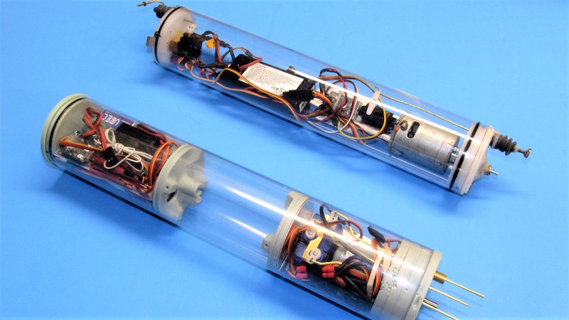
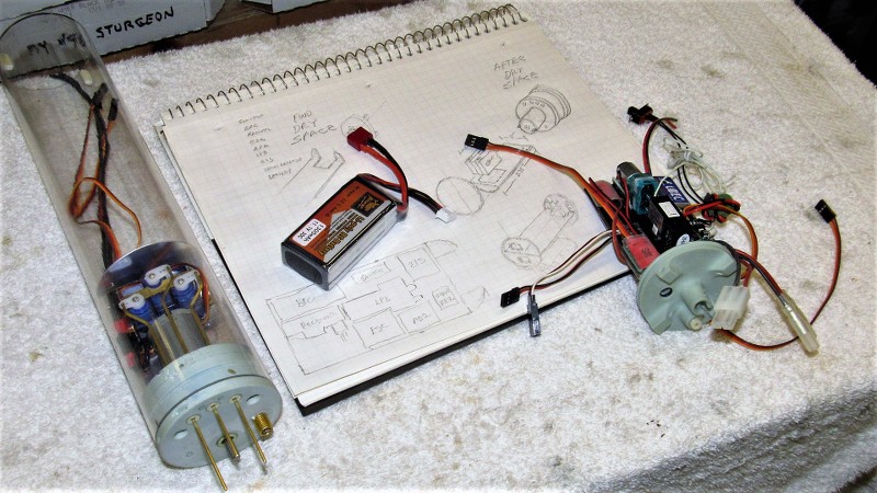
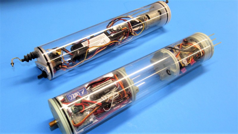
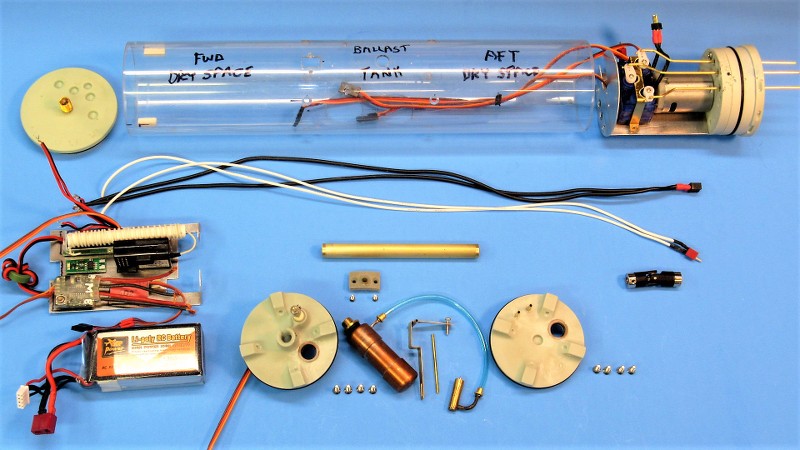
    I've been droning on about the HUNLEY model itself for long enough. Now that you have a grasp of what I'm doing to control yaw and pitch, lets give all that nonsense a rest and look at the module I'm putting together to control, propel, and change the submarines displacement. In foreground is a preliminary fit of my water tight cylinder (WTC). In background is the cylinder provided by the client. Mine, of course, is superior in all regards: it has a ballast tank, geared motor, easy access to all internal devices and mechanisms, and room for a battery of much greater capacity.

    The WTC's forward end is to the left. It's in that space that most of the electronic devices that power, control, and manage the ballast water are housed – those devices atop an aluminum tray. Beneath that is housed the single 11.1-volt Lithium-polymer battery, with enough capacity to run the HUNLEY for well over an hour.

    Dividing my WTC into three compartments are two internal bulkheads. The forward space was just described, the middle space is the ballast tank, which is of the 'soft' type; that is to say, it's always subject to the ambient water pressure. The after dry space houses the geared propulsion motor, three servos (rudder, propeller pitching, and bow planes), and Low Pressure Blower (LPB) which is used to blow the ballast tank dry once the HUNLEY's snorkel broaches the surface.

    What you're looking at is an initial fit-check, it is far from being a finished product at this point.


    I don't pull this stuff out of magic hat. No. A lot of thought goes into the WTC. Where will the devices be arranged with one another to achieve the shortest cable-runs between them? Where to best position the devices to make access an easy matter? How much water must the ballast tank contain to achieve a reasonably high surfaced trim waterline when emptied? All these problems and more start in my brain, they begin to solidify on graph-paper, and finally, I start to mock-up the arrangement – first with cardboard stand-ins, then, when happy with those renderings, I start manufacturing the foundations and other hardware to mount the devices to get them to work together in the most efficient manner.

    Such paper studies lead to simplification. The most efficient system contains the minimum number of elements to achieve the goals of the system! The initial paper studies are always over-complex plumber's nightmares. But, after examining your two-dimensional representation you see where things can be improved... you make more drawings; each one more rational than the one before. The process continues till clarity of purpose is achieved. Only then is it time to get physical!


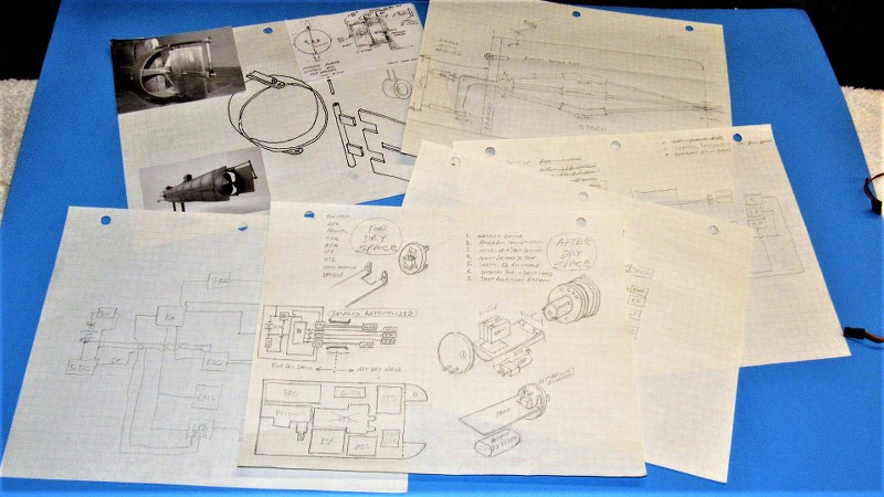
    To illustrate what clarity in my world means:


    All the expensive stuff is up high-and-dry atop an aluminum tray. Down below in the nasty bilge space goes the battery. If I get a leak I don't care if the battery takes a bath, but I do want the electronic devices to stay out of the wet. In this game things eventually get wet! So, you design for that inevitable incident. Oh, I never operate in salt-water!


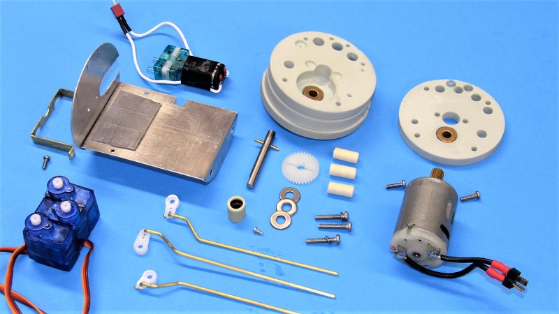
    OK. Backing up to the beginning of the forward dry space device tray: It started out as a cardboard mock-up. Several versions of this thing were scissored out and test fitted till I had the right geometry. From that point the hero cardboard tray was used as a template to mark out a sheet of hard, .030” thick Aluminum.


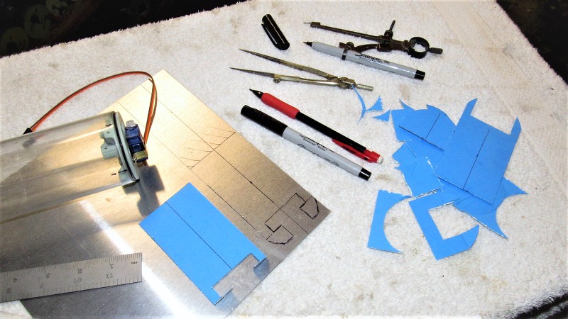
    Using double-sided tape (servo tape to some of you) I did a preliminary arrangement of the devices atop the tray. I was over-optimistic thinking I could also make room for the LPB (a neat little diaphragm pump-motor unit) atop the tray. That had to change! Other issues as to device locations were also identified here. It's amazing what you realize how much you missed during the paper study as you begin to apply the two-dimensional representation to a three-dimensional reality! And how quickly one is revealed to be a dumb-ass during this revelation.


    So!...

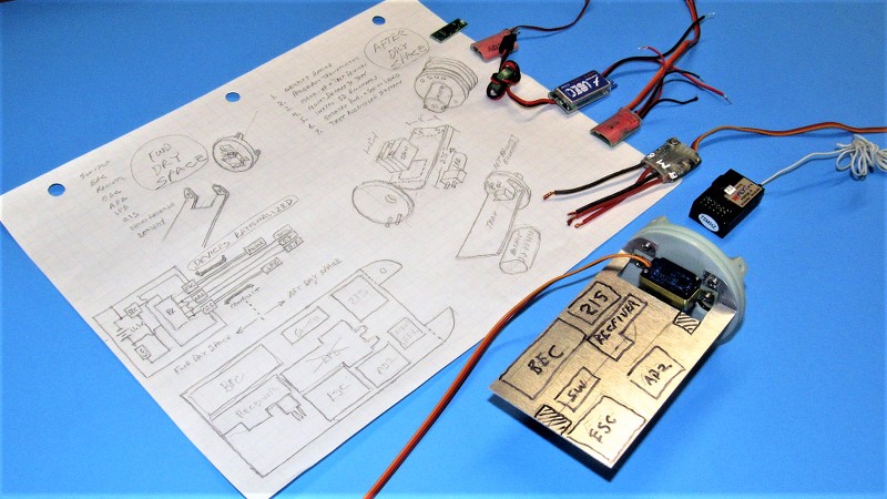
    ...changes are made! First to the paper-study, then to the actual device tray. I found room for the LPB atop the servos in the after dry space. The extra wiring necessitated going to a larger diameter conduit that passes through the ballast tank. But, that's life in the big city! Here I've re-arranged the position of the devices. Now things are making a bit more sense. Note the device block-diagram/schematic on the left side of the drawing – this done to identify the arrangement that would give me the shortest runs between cables and leads.

    I also identified where I would have to remove more Aluminum – to make a passage for the battery cable, aft. And more of an opening for the wiring that had to pass aft through the ballast tank conduit which was beneath the tray.


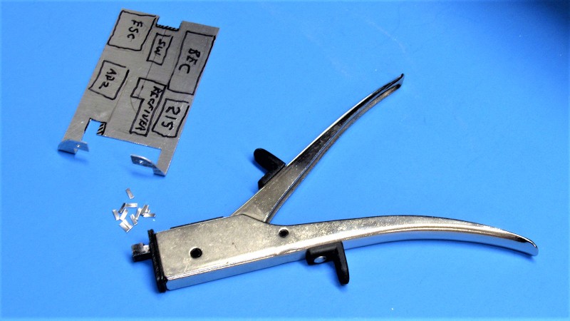
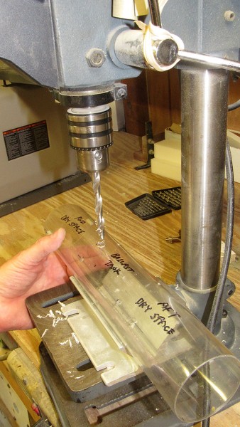
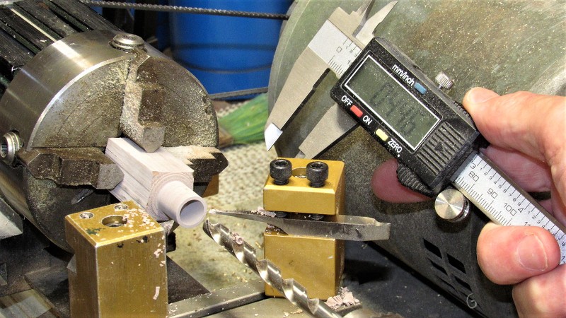
    Here's a neat tool for making inside-cuts into soft metals of small gauge: It's called a 'nibbler'. And works just like that, a jaw and anvil that shears away small chunks of sheet-metal with each pull of the handle. It gets into places where other tools either can't or require a lot of awkward maneuvering to make the cut.


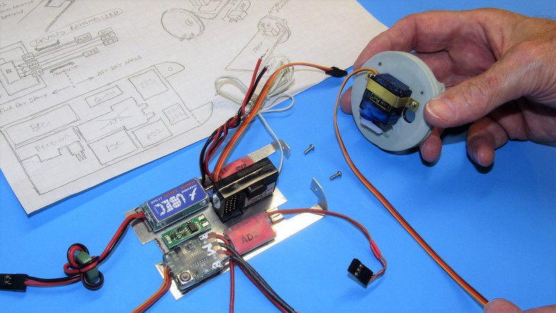
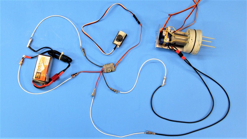
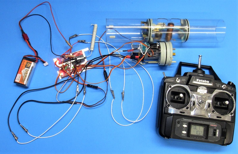
    Today's electronic devices produced for the hobby industry are of an exceptionally high standard. However, it's a fools game to just plug everything into a complete system without first certifying that each device works as advertised. Such was the case with the receiver, battery eliminator circuit, electronic switch, mission switch, angle-keeper, electronic speed controller, LPB, propulsion motor, and four servos. Each one received my close examination as it was tested for proper operation.

    Here I've adjusted the battery eliminator circuit to provide the 5.25-volts demanded by the receiver bus and other devices that dine from that trough. Correct output verified with my handy-dandy, wonder, multi-meter. Note the extensive use of jumper wires to interconnect the device to battery and meter.


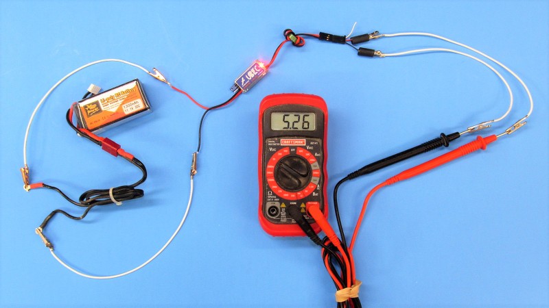
    The propulsion motor electronic speed controller was tested and its operating parameters established with the aid of a 'servo-setter'. Again, hook up was simplified with the use of jumpers. The LPB switch, and servos were tested in a similar fashion.


    And that, boy's and girl's, is how I get ten-pounds of **** into a five-pound bag!


    Oh!... a bonus posting. Here's a quick look at some underwater shenanigans as I mixed it up with two other submarines at the resent Georgia SubFest event: https://youtu.be/t7gDrTtxnWo

    Who is John Galt?

    Comment

    • redboat219
      Admiral
      • Dec 2008
      • 2735

      Fabulous work boss. I bet you already got a big folder of those sketches through the years. How I'd love to get a copy . Can you scan and load them onto an SD card and tuck it in a PB sandwich, I'll pick it up later.
      Make it simple, make strong, make it work!

      Comment

      • He Who Shall Not Be Named
        Moderator
        • Aug 2008
        • 12256

        Originally posted by redboat219
        Fabulous work boss. I bet you already got a big folder of those sketches through the years. How I'd love to get a copy . Can you scan and load them onto an SD card and tuck it in a PB sandwich, I'll pick it up later.
        ... and while your here you can...
        Who is John Galt?

        Comment

        • Ken_NJ
          Captain
          • Sep 2014
          • 745

          Originally posted by He Who Shall Not Be Named
          Oh!... a bonus posting. Here's a quick look at some underwater shenanigans as I mixed it up with two other submarines at the resent Georgia SubFest event: https://youtu.be/t7gDrTtxnWo
          That was fun and unexpected shenanigans!

          Comment

          • He Who Shall Not Be Named
            Moderator
            • Aug 2008
            • 12256

            Originally posted by Ken_NJ

            That was fun and unexpected shenanigans!
            You could not have possibly cut that turn any closer! Well done. Your propeller wash actually rolled the KAIRYU a bit.
            Who is John Galt?

            Comment

            • redboat219
              Admiral
              • Dec 2008
              • 2735

              Originally posted by He Who Shall Not Be Named

              You could not have possibly cut that turn any closer!
              This close enough?

               
              Make it simple, make strong, make it work!

              Comment

              • biggsgolf
                Captain
                • Jan 2020
                • 720

                Originally posted by He Who Shall Not Be Named

                I did clear-coat first when I was painting balsa airplanes, but that was a long time ago. If you first mount a length of masking tape on a clean cutting board and cut away the factory edge, you won't have bleed problems on a well filled, primed, and painted surface.

                What I made there, from a length of 1/8" diameter machine-brass rod, was a common old bow type drafter's pen. Old school! In Junior High we would make these things in Metal Shop, then, next period, use them during Mechanical Drawing. So... they teach this stuff anymore?! Nice thing about that pen is that opening the quill space and adjusting the viscosity of the paint, you can get a reasonably large variance in line width.

                Click image for larger version

Name:	DSCN0127 (3).JPG
Views:	414
Size:	59.7 KB
ID:	154314Click image for larger version

Name:	DSCN0134 (2).JPG
Views:	420
Size:	66.3 KB
ID:	154315Click image for larger version

Name:	DSCN0183 (3).JPG
Views:	419
Size:	99.1 KB
ID:	154316

                TRIBUT... I must have TRIBUT! for I am a vengeful, angry, demanding, spiteful God! TRIBUT!


                David
                ...reaching for the med's I missed this morning
                Yes, you are the Lord of all we do, or try to do as you have so generously shared with us! Thankyou soooo much, words cannot show our appreciation… we can only show you our success made possible by you.

                Comment

                • He Who Shall Not Be Named
                  Moderator
                  • Aug 2008
                  • 12256

                  Originally posted by biggsgolf

                  Yes, you are the Lord of all we do, or try to do as you have so generously shared with us! Thankyou soooo much, words cannot show our appreciation… we can only show you our success made possible by you.
                  Damn!... you gotta come up for air, sometime!

                  David
                  Who is John Galt?

                  Comment

                  • He Who Shall Not Be Named
                    Moderator
                    • Aug 2008
                    • 12256


                    I've almost completed the assembly of the HUNLEY's WTC; the system that will propel, control, and manage the ballast water used to transition the model submarine from surfaced to submerged trim and back again. All the sub-assemblies have been assembled and integrated into the whole. I've mocked-up all the devices and have got them to operate in concert with the transmitter that will permit remote operation of the HUNLEY model when it's operating on and under the water. The only task remaining is the routing of the wiring through the conduit, shorten some leads, make up the magnetically activated mission-switch, and integrate the WTC with the HUNLEY's linkages.

                    The Forward Dry Space A removable forward bulkhead pops on and off for easy access for battery swap or to get at the devices mounted above the battery. By removing two mounting screws the entire device tray can be slid out for even better access to the devices, enough slack in the power and control wires has been provided for this. The receiver antenna has been wrapped around a mandrel eliminating the need to run the antenna external of the WTC's cylinder. On the dry side of the forward ballast bulkhead resides the ballast servo.

                    The Ballast Tank Within the ballast tank is a gas bottle and blow valve to provide an emergency back-up means of blowing the water out. The receivers fail-safe point for that channel has been set to drive the ballast servo to full extension in the 'blow' position should the receiver fail to see a transmitted signal. At all other times the transmitter sends only enough 'blow' position to activate the LPB, but not enough travel to engage the emergency blow valve. Normal blow is via LPB only. Emergency blow both the LPB and gas source work to discharge ballast water.

                    The After Dry Space Within this space is housed the motor bulkhead with installed 380 sized motor that is geared 3:1 to the drive-shaft. Set into the motor bulkhead are three servo pushrod seals and single drive-shaft seal. Mounted on an aluminum tray on the dry side of the motor bulkhead are the three servos (rudder, bow planes, and propeller shaft pitching mechanism), and on the other side of the tray is mounted the little diaphragm pump-motor (LPB) used to blow air into the ballast tank during a normal blow operation.


                    For over three decades we manufactured and sold hundreds of WTC's to the world market. Now retired I make occasional use of the jigs, fixtures, templates, and parts still at hand in the shop for the occasional 'fun' job like this. Here I'm using one of the 2.5" diameter mark-off templates to identify fastener, vent, and flood-drain hole locations that will be drilled and machined out.


                    Poly Vinyl Chloride (PVC) Lexan plastic is very tolerant of drilling, milling, and grinding and will not crack or craze as readily as the cheaper and more available Acrylic plastic. Lexan has been our cylinder material of choice from the beginning. Here I'm drilling a starter hole that will later be milled out as a square hole to accommodate the ballast tank vent valve body. The cylinder for this job is 2.5" in diameter with a wall thickness of 1/16".


                    The brass tube conduit permits dry passage of the power and control cables and leads between forward and after dry spaces. Here I've attached the two internal ballast bulkheads together with the aid of the conduit to demonstrate how the bulkheads divide the cylinder into three discrete spaces. As you can see the cylinder has already been machined with ballast tank flood-drain holes and holes for the internal bulkhead securing screws. Installed are the ballast linkage bell crank within, and the tank vent valve atop the cylinder. The black Electrician's tape covers the holes that pass the ballast linkage bell crank and hold its pivot pin in place.


                    As this particular WTC had to pass many more cables and servo leads than the mass-produced varients of the WTC's we sold, a bigger diameter conduit was needed. So, I drilled out the original cast-in-place O-rings that made watertight the original, smaller diameter, conduit -- you see, in cut-away, to the left, one of the stock ballast bulkheads demonstrating the cast-in-place O-rings typically used. As you can see the new conduit is much larger in diameter. That meant fabrication of a new set of sealing O-rings for the ballast bulkheads.

                    The two brass nipples you see inset within the after ballast bulkhead will eventually make up to lengths of flexible hose. That plumbing will route air from the surface -- through the HUNLEY's snorkel tubes -- to the LPB which will discharge that air into the ballast tank, blowing out the ballast water during a normal blow.

                    In foreground are cut-aways of the shaft and pushrod seals we produced and used with our line of WTC's. It's all about keeping the water out and the magic in!


                    To the left is a typical seal designed to make watertight a rotating shaft. The sealing element is a rubber 'cup seal' that features a chevron shaped inner and outer lip that makes a light but effective seal between shaft and seal body. This type seal is best employed for shafts that rotate instead of traveling axially. However, manufacture is labor intensive as the plastic resin body requires lathe work. Adding to the seals complexity is the need of a close tolerance Oilite bearing to prevent wobble or lateral motion of the rotating shaft within the seal body -- if unrestricted such motion would unseat the seal, resulting in water getting past it; that bearing is there only to keep the shaft centered, not for axial thrust loads.

                    For making watertight axial traveling shafts, such as pushrods, simple embedded O-rings within cast resin bodies suffice. Two sizes on display here, 1/8" and 1/16" diameter pushrod seals. Note that the smaller pushrod seal features two encapsulated O-rings, a recent improvement -- a bit more friction, but a sure-fire water-stopper.


                    Once an appropriate diameter of brass tube was identified to serve as this WTC's conduit I selected an O-ring diameter that made a slight interference fit to the conduit, then milled into one side of a ballast bulkhead a depression that made a slight interference fit to the outside of the O-ring. The two O-rings would make watertight the conduit where it penetrates the ballast bulkheads. Each O-ring is held in place with a RenShape retaining ring secured in place with CA.


                    The conduit O-ring retaining rings were turned from a raw chunk of dense RenShape model-making medium. Here, my over-achieving Taig lathe is pretending to work like a turret-lathe. I love these machines: simple, sturdy, and great support from the factory when you need accessories and repair parts. If you don't have a Taig lathe... get one!


                    I needed two retaining rings, but three gave me a little 'insurance'.


                    And here are all the sub-assemblies ready for installation within the Lexan cylinder of the HUNLEY's WTC.

                    This shot gives you some appreciation why I had to engineer a larger diameter conduit -- that thing was gonna be fed a lot of spaghetti! The power cables to the LPB, The power cables to the propulsion motor, and the three servo three-wire leads would all pass through the ballast tank.


                    I disassembled the motor bulkhead and pulled the devices off the tray to give you an idea of what all the nonsense back aft is about. The cast resin motor bulkhead is made up of the forward motor-mount which bolts to the forward face of the motor bulkhead proper. Sandwiched between the two parts is the pinion gear that drives the motor-shaft. That shaft passing through a cup type watertight seal. Set into the motor bulkhead and projecting into the water are the watertight seals through which the servo pushrods travel axially, and the motor shaft rotates. On the bottom of the tray sits the three servos held in place with servo-tape and a bracket. On the bottom face of the tray is the servo-taped LPB.


                    Before stuffing all the cables and leads through the conduit I hard-wired everything together with jumpers and operated the devices as a system. So configured any problems are easily fixed with things still accessible. Much better than if I had to fish leads and cables out of the tight confines of the conduit with the inevitable need to de-solder, fix/replace, then solder things back together.

                    Check twice... cut once!

                    Who is John Galt?

                    Comment

                    • He Who Shall Not Be Named
                      Moderator
                      • Aug 2008
                      • 12256

                      The only movie Ellie and I ever secured screen-credit. https://youtu.be/GF-ausxLWsM

                      Opening Credits, 3:15
                      Closing Credits, 1:18:24

                      David
                      We Made Plan 9 Look Good!
                      Who is John Galt?

                      Comment

                      • Monahan Steam Models
                        Captain
                        • Apr 2020
                        • 755

                        Originally posted by He Who Shall Not Be Named
                        I've almost completed the assembly of the HUNLEY's WTC; the system that will propel, control, and manage the ballast water used to transition the model submarine from surfaced to submerged trim and back again. All the sub-assemblies have been assembled and integrated into the whole. I've mocked-up all the devices and have got them to operate in concert with the transmitter that will permit remote operation of the HUNLEY model when it's operating on and under the water. The only task remaining is the routing of the wiring through the conduit, shorten some leads, make up the magnetically activated mission-switch, and integrate the WTC with the HUNLEY's linkages.

                        The Forward Dry Space A removable forward bulkhead pops on and off for easy access for battery swap or to get at the devices mounted above the battery. By removing two mounting screws the entire device tray can be slid out for even better access to the devices, enough slack in the power and control wires has been provided for this. The receiver antenna has been wrapped around a mandrel eliminating the need to run the antenna external of the WTC's cylinder. On the dry side of the forward ballast bulkhead resides the ballast servo.

                        The Ballast Tank Within the ballast tank is a gas bottle and blow valve to provide an emergency back-up means of blowing the water out. The receivers fail-safe point for that channel has been set to drive the ballast servo to full extension in the 'blow' position should the receiver fail to see a transmitted signal. At all other times the transmitter sends only enough 'blow' position to activate the LPB, but not enough travel to engage the emergency blow valve. Normal blow is via LPB only. Emergency blow both the LPB and gas source work to discharge ballast water.

                        The After Dry Space Within this space is housed the motor bulkhead with installed 380 sized motor that is geared 3:1 to the drive-shaft. Set into the motor bulkhead are three servo pushrod seals and single drive-shaft seal. Mounted on an aluminum tray on the dry side of the motor bulkhead are the three servos (rudder, bow planes, and propeller shaft pitching mechanism), and on the other side of the tray is mounted the little diaphragm pump-motor (LPB) used to blow air into the ballast tank during a normal blow operation.


                        For over three decades we manufactured and sold hundreds of WTC's to the world market. Now retired I make occasional use of the jigs, fixtures, templates, and parts still at hand in the shop for the occasional 'fun' job like this. Here I'm using one of the 2.5" diameter mark-off templates to identify fastener, vent, and flood-drain hole locations that will be drilled and machined out.


                        Poly Vinyl Chloride (PVC) Lexan plastic is very tolerant of drilling, milling, and grinding and will not crack or craze as readily as the cheaper and more available Acrylic plastic. Lexan has been our cylinder material of choice from the beginning. Here I'm drilling a starter hole that will later be milled out as a square hole to accommodate the ballast tank vent valve body. The cylinder for this job is 2.5" in diameter with a wall thickness of 1/16".


                        The brass tube conduit permits dry passage of the power and control cables and leads between forward and after dry spaces. Here I've attached the two internal ballast bulkheads together with the aid of the conduit to demonstrate how the bulkheads divide the cylinder into three discrete spaces. As you can see the cylinder has already been machined with ballast tank flood-drain holes and holes for the internal bulkhead securing screws. Installed are the ballast linkage bell crank within, and the tank vent valve atop the cylinder. The black Electrician's tape covers the holes that pass the ballast linkage bell crank and hold its pivot pin in place.


                        As this particular WTC had to pass many more cables and servo leads than the mass-produced varients of the WTC's we sold, a bigger diameter conduit was needed. So, I drilled out the original cast-in-place O-rings that made watertight the original, smaller diameter, conduit -- you see, in cut-away, to the left, one of the stock ballast bulkheads demonstrating the cast-in-place O-rings typically used. As you can see the new conduit is much larger in diameter. That meant fabrication of a new set of sealing O-rings for the ballast bulkheads.

                        The two brass nipples you see inset within the after ballast bulkhead will eventually make up to lengths of flexible hose. That plumbing will route air from the surface -- through the HUNLEY's snorkel tubes -- to the LPB which will discharge that air into the ballast tank, blowing out the ballast water during a normal blow.

                        In foreground are cut-aways of the shaft and pushrod seals we produced and used with our line of WTC's. It's all about keeping the water out and the magic in!


                        To the left is a typical seal designed to make watertight a rotating shaft. The sealing element is a rubber 'cup seal' that features a chevron shaped inner and outer lip that makes a light but effective seal between shaft and seal body. This type seal is best employed for shafts that rotate instead of traveling axially. However, manufacture is labor intensive as the plastic resin body requires lathe work. Adding to the seals complexity is the need of a close tolerance Oilite bearing to prevent wobble or lateral motion of the rotating shaft within the seal body -- if unrestricted such motion would unseat the seal, resulting in water getting past it; that bearing is there only to keep the shaft centered, not for axial thrust loads.

                        For making watertight axial traveling shafts, such as pushrods, simple embedded O-rings within cast resin bodies suffice. Two sizes on display here, 1/8" and 1/16" diameter pushrod seals. Note that the smaller pushrod seal features two encapsulated O-rings, a recent improvement -- a bit more friction, but a sure-fire water-stopper.


                        Once an appropriate diameter of brass tube was identified to serve as this WTC's conduit I selected an O-ring diameter that made a slight interference fit to the conduit, then milled into one side of a ballast bulkhead a depression that made a slight interference fit to the outside of the O-ring. The two O-rings would make watertight the conduit where it penetrates the ballast bulkheads. Each O-ring is held in place with a RenShape retaining ring secured in place with CA.


                        The conduit O-ring retaining rings were turned from a raw chunk of dense RenShape model-making medium. Here, my over-achieving Taig lathe is pretending to work like a turret-lathe. I love these machines: simple, sturdy, and great support from the factory when you need accessories and repair parts. If you don't have a Taig lathe... get one!


                        I needed two retaining rings, but three gave me a little 'insurance'.


                        And here are all the sub-assemblies ready for installation within the Lexan cylinder of the HUNLEY's WTC.

                        This shot gives you some appreciation why I had to engineer a larger diameter conduit -- that thing was gonna be fed a lot of spaghetti! The power cables to the LPB, The power cables to the propulsion motor, and the three servo three-wire leads would all pass through the ballast tank.


                        I disassembled the motor bulkhead and pulled the devices off the tray to give you an idea of what all the nonsense back aft is about. The cast resin motor bulkhead is made up of the forward motor-mount which bolts to the forward face of the motor bulkhead proper. Sandwiched between the two parts is the pinion gear that drives the motor-shaft. That shaft passing through a cup type watertight seal. Set into the motor bulkhead and projecting into the water are the watertight seals through which the servo pushrods travel axially, and the motor shaft rotates. On the bottom of the tray sits the three servos held in place with servo-tape and a bracket. On the bottom face of the tray is the servo-taped LPB.


                        Before stuffing all the cables and leads through the conduit I hard-wired everything together with jumpers and operated the devices as a system. So configured any problems are easily fixed with things still accessible. Much better than if I had to fish leads and cables out of the tight confines of the conduit with the inevitable need to de-solder, fix/replace, then solder things back together.

                        Check twice... cut once!

                        Always enjoy seeing your work!

                        Comment

                        • He Who Shall Not Be Named
                          Moderator
                          • Aug 2008
                          • 12256

                          Originally posted by Monahan Steam Models

                          Always enjoy seeing your work!
                          Thank you, sir. It's for the truely talented (gear-heads like you, pal!) I write this stuff for. I get at least as much from your work as you get from mine.

                          David
                          Who is John Galt?

                          Comment

                          • SteveNeill
                            Commander
                            • Apr 2020
                            • 315

                            I have to say, you keep this hobby alive and interesting. Thanks David for pressing on.

                            Comment

                            • He Who Shall Not Be Named
                              Moderator
                              • Aug 2008
                              • 12256

                              Like it or not we're all in a head-long foot-race against the Reaper. Might as well have fun with it and keep flashing him the double-finger each time we round a turn in the road. To me, this r/c submarining is... fun.


                              David
                              Who is John Galt?

                              Comment

                              • SteveNeill
                                Commander
                                • Apr 2020
                                • 315

                                I could not agree more.

                                Comment

                                Working...