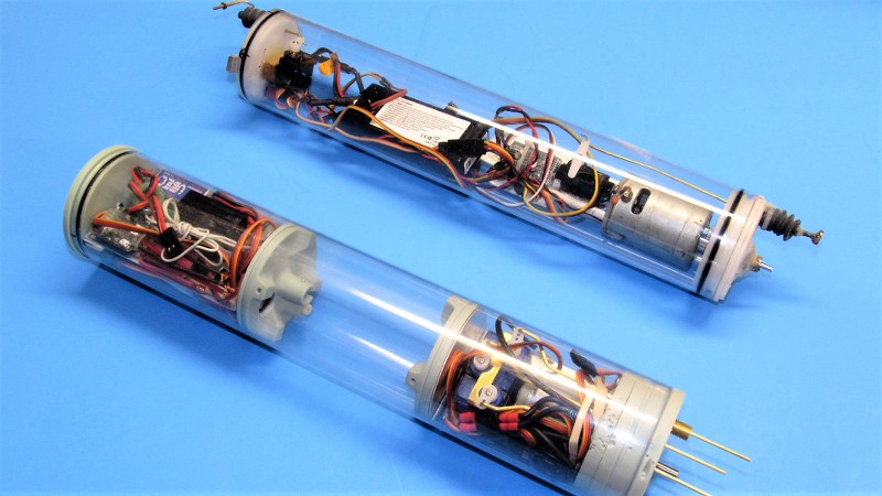
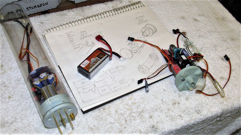
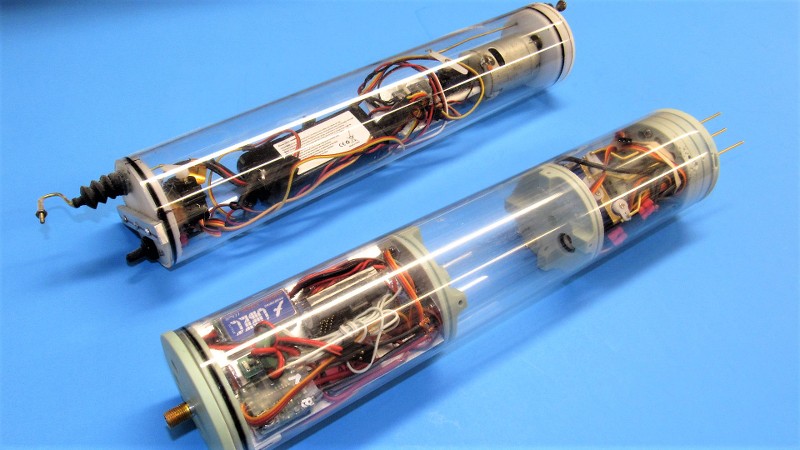
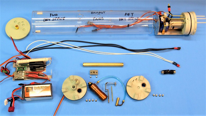
I've been droning on about the HUNLEY model itself for long enough. Now that you have a grasp of what I'm doing to control yaw and pitch, lets give all that nonsense a rest and look at the module I'm putting together to control, propel, and change the submarines displacement. In foreground is a preliminary fit of my water tight cylinder (WTC). In background is the cylinder provided by the client. Mine, of course, is superior in all regards: it has a ballast tank, geared motor, easy access to all internal devices and mechanisms, and room for a battery of much greater capacity.
The WTC's forward end is to the left. It's in that space that most of the electronic devices that power, control, and manage the ballast water are housed – those devices atop an aluminum tray. Beneath that is housed the single 11.1-volt Lithium-polymer battery, with enough capacity to run the HUNLEY for well over an hour.
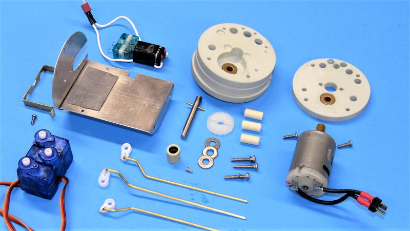
Dividing my WTC into three compartments are two internal bulkheads. The forward space was just described, the middle space is the ballast tank, which is of the 'soft' type; that is to say, it's always subject to the ambient water pressure. The after dry space houses the geared propulsion motor, three servos (rudder, propeller pitching, and bow planes), and Low Pressure Blower (LPB) which is used to blow the ballast tank dry once the HUNLEY's snorkel broaches the surface.
What you're looking at is an initial fit-check, it is far from being a finished product at this point.
I don't pull this stuff out of magic hat. No. A lot of thought goes into the WTC. Where will the devices be arranged with one another to achieve the shortest cable-runs between them? Where to best position the devices to make access an easy matter? How much water must the ballast tank contain to achieve a reasonably high surfaced trim waterline when emptied? All these problems and more start in my brain, they begin to solidify on graph-paper, and finally, I start to mock-up the arrangement – first with cardboard stand-ins, then, when happy with those renderings, I start manufacturing the foundations and other hardware to mount the devices to get them to work together in the most efficient manner.
Such paper studies lead to simplification. The most efficient system contains the minimum number of elements to achieve the goals of the system! The initial paper studies are always over-complex plumber's nightmares. But, after examining your two-dimensional representation you see where things can be improved... you make more drawings; each one more rational than the one before. The process continues till clarity of purpose is achieved. Only then is it time to get physical!
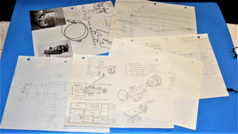
To illustrate what clarity in my world means:
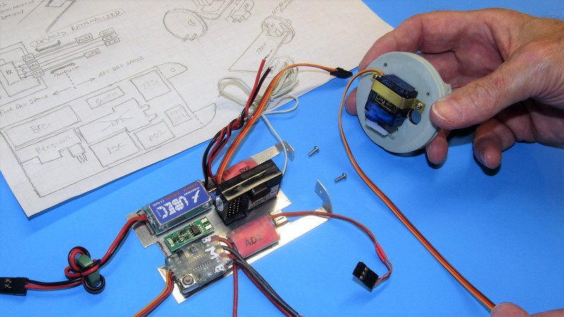
All the expensive stuff is up high-and-dry atop an aluminum tray. Down below in the nasty bilge space goes the battery. If I get a leak I don't care if the battery takes a bath, but I do want the electronic devices to stay out of the wet. In this game things eventually get wet! So, you design for that inevitable incident. Oh, I never operate in salt-water!

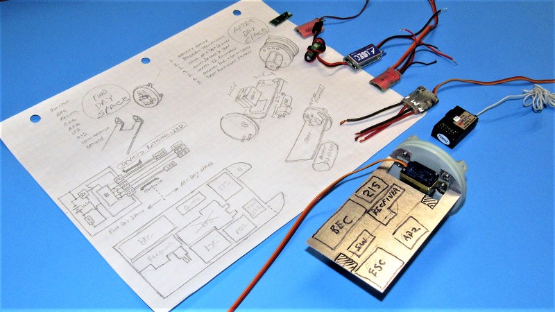
OK. Backing up to the beginning of the forward dry space device tray: It started out as a cardboard mock-up. Several versions of this thing were scissored out and test fitted till I had the right geometry. From that point the hero cardboard tray was used as a template to mark out a sheet of hard, .030” thick Aluminum.
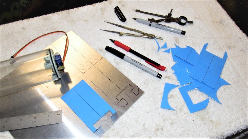
Using double-sided tape (servo tape to some of you) I did a preliminary arrangement of the devices atop the tray. I was over-optimistic thinking I could also make room for the LPB (a neat little diaphragm pump-motor unit) atop the tray. That had to change! Other issues as to device locations were also identified here. It's amazing what you realize how much you missed during the paper study as you begin to apply the two-dimensional representation to a three-dimensional reality! And how quickly one is revealed to be a dumb-ass during this revelation.
So!...
...changes are made! First to the paper-study, then to the actual device tray. I found room for the LPB atop the servos in the after dry space. The extra wiring necessitated going to a larger diameter conduit that passes through the ballast tank. But, that's life in the big city! Here I've re-arranged the position of the devices. Now things are making a bit more sense. Note the device block-diagram/schematic on the left side of the drawing – this done to identify the arrangement that would give me the shortest runs between cables and leads.
I also identified where I would have to remove more Aluminum – to make a passage for the battery cable, aft. And more of an opening for the wiring that had to pass aft through the ballast tank conduit which was beneath the tray.
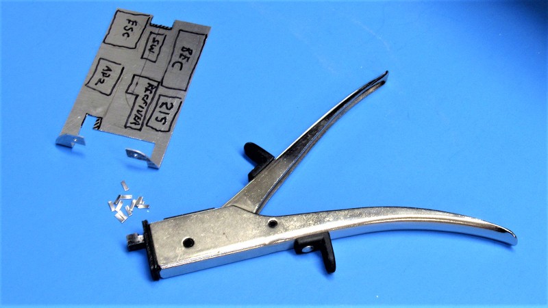
Here's a neat tool for making inside-cuts into soft metals of small gauge: It's called a 'nibbler'. And works just like that, a jaw and anvil that shears away small chunks of sheet-metal with each pull of the handle. It gets into places where other tools either can't or require a lot of awkward maneuvering to make the cut.

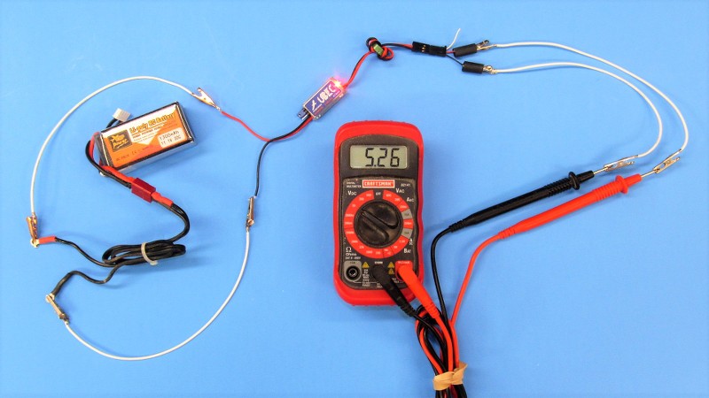
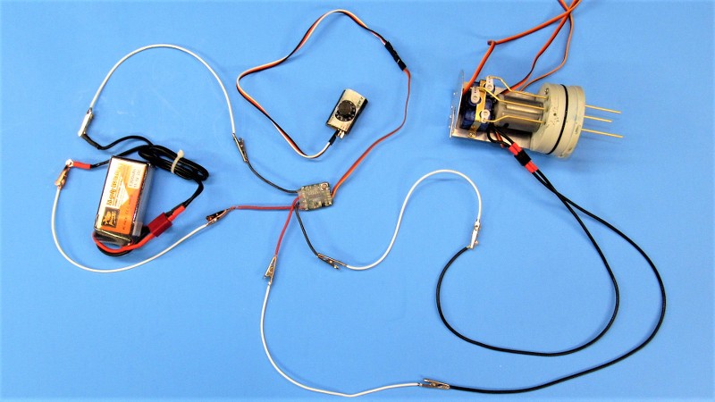
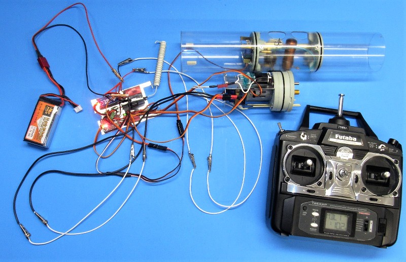
Today's electronic devices produced for the hobby industry are of an exceptionally high standard. However, it's a fools game to just plug everything into a complete system without first certifying that each device works as advertised. Such was the case with the receiver, battery eliminator circuit, electronic switch, mission switch, angle-keeper, electronic speed controller, LPB, propulsion motor, and four servos. Each one received my close examination as it was tested for proper operation.
Here I've adjusted the battery eliminator circuit to provide the 5.25-volts demanded by the receiver bus and other devices that dine from that trough. Correct output verified with my handy-dandy, wonder, multi-meter. Note the extensive use of jumper wires to interconnect the device to battery and meter.
The propulsion motor electronic speed controller was tested and its operating parameters established with the aid of a 'servo-setter'. Again, hook up was simplified with the use of jumpers. The LPB switch, and servos were tested in a similar fashion.
And that, boy's and girl's, is how I get ten-pounds of **** into a five-pound bag!
Oh!... a bonus posting. Here's a quick look at some underwater shenanigans as I mixed it up with two other submarines at the resent Georgia SubFest event: https://youtu.be/t7gDrTtxnWo





Comment