
 Tweet
Tweet
Dave drives boats like an old Wide World of Sports demolition derby. He needs backup adhesion.
-
Of the approximately 40,000 men who served on U-boats in WWII, it is estimated that around 28,000 to 30,000 lost their lives. -
Of the approximately 40,000 men who served on U-boats in WWII, it is estimated that around 28,000 to 30,000 lost their lives.Comment
-
David,
Keep the prop as it is, they used steel to make the props, lifespan of a type XXIII wasn't expected be high, and they has shortage of brons that period of time.
I added 5 or 6 circular holes at the keel, totally off scale, but effecient enough to lower and raise the boat without troubles.
Manfred.I went undergroundComment
-
Yeah, I know that about the materials shortage and have considered doing just that with the propeller, Manfred. Good point.
Great... you task me yet again. You European PITAs are getting under my skin with your anal-retentive, demanding, no holds barred call to perfection. Leave me alone, damnit! I'm old, infirm, wobbly, and out of my mind.
David
(last time I checked)Who is John Galt?Comment
-
Stop whining at tasking, get this build done, pop her cherry and start driving her.
Manfred.
Captain AnalI went undergroundComment
-
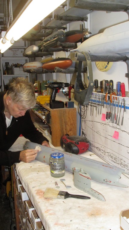
I've fielded enough questions asking how I've arranged my shop to warrant a slight departure from the current Type-23 model discussion and provide a little insight on one method used to make my hand-tools accessible.
And that is to simply hang most of the files, screwdrivers, knifes, hemostats, and small pliers off of magnets. This picture shows one of the four workstations in my former one-car garage, aka the sprawling industrial complex of D&E Miniatures, hidden deep within the earth and protected by fields of intensified Gama radiation and Krell steel.
Note the many tools hanging off the wall with the aid of magnets. Each easy to identify with a quick glance, and within easy reach.
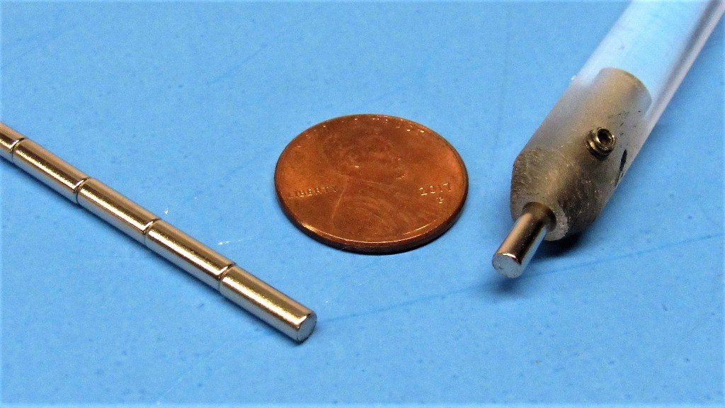
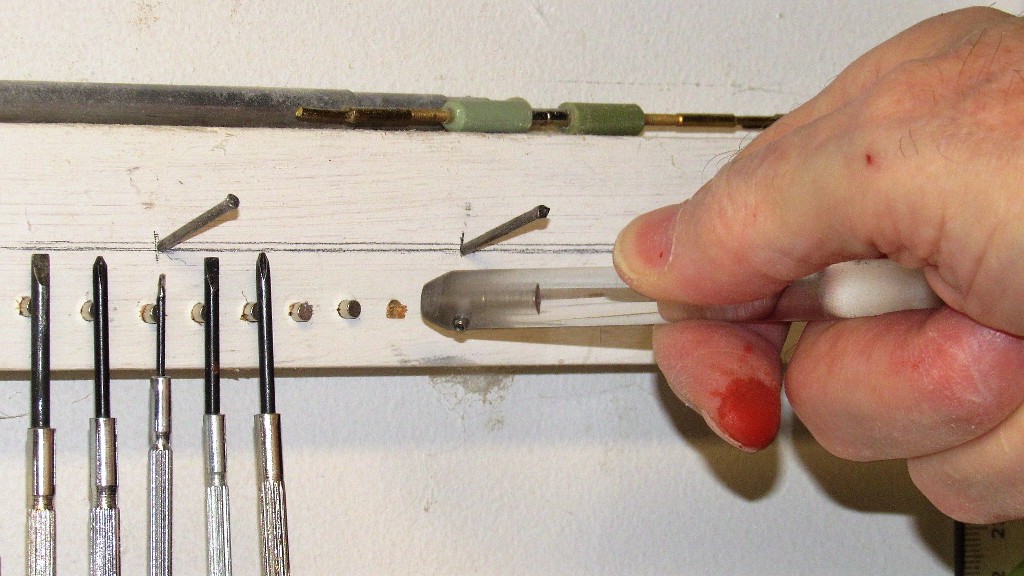
The magnets themselves are cylindrical and are pushed into holes drilled into a wooden carriage screwed into the wall or edge of a worktable. The holes slightly smaller than the diameter of the cylindrical magnet (which, in the day, I bought by the hundreds). A piece of clear acrylic rod was turned into a magnet insertion tool by drilling a bore at one end twice the depth of a magnet.
A set screw permitted me to lock one of these magnets in place so that when a magnet, to be press-fit into the wooden carriage, is inserted (and held in place within the tool by the setscrew retained internal magnet) it projects a distance from the end of the tool that equates to the depth it will penetrate the carriage hole.
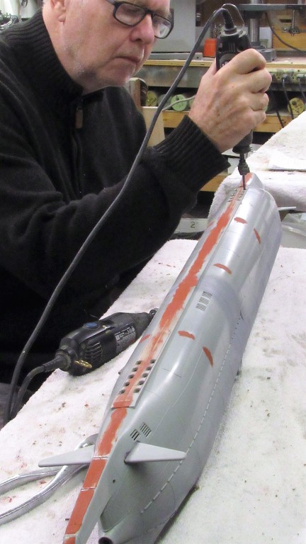
OK, back to the Type-23 Bronco kit...
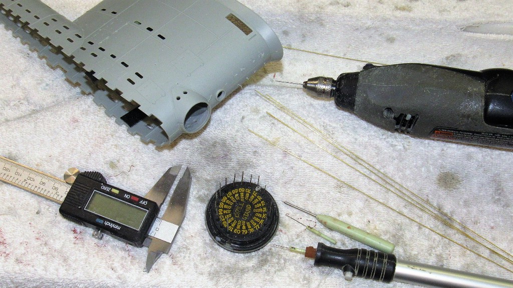
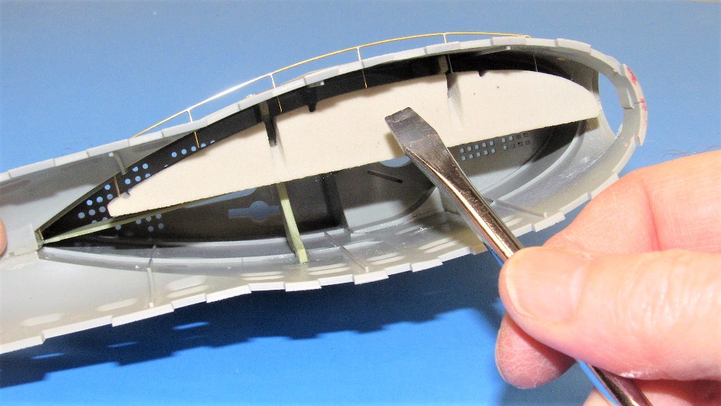
The previously marked out ovoid flood-drain holes in the keel were opened up with drill and worked with round and flat jeweler's files.
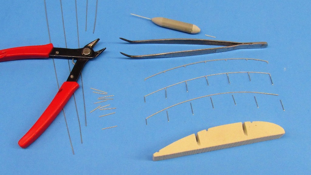
The kit supplied plastic ladder rungs that permitted access to the bridge from deck level are fine for a well-protected static display, but wholly unsuited for the rough handling an r/c model submarine will be subjected to. So, I substituted .020-inch diameter brass rod.
I identified that point along the length of the tapered jaws of a needle-nose pliers whose width was that of a ladder rung. One of the jaws by wrapping with two pieces of masking tape to identify that specific width. Bending the rungs at that point in the tool insured consistency as I made the required number of ladder rings for this model.
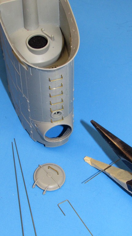
Slight indentations on the leading edge of the sail were where the plastic ladder rungs would be glued. I drilled through these with a .023-inch drill bit. Later, after all painting had been done, the metal ladder rungs would be inserted and glued in place from the inside of the sail.
The top of the sail, after gluing it in place, required a bit of filing and sanding to get its edge even with the sides of the sail. Before doing that, I pencil marked both sides of the seam.
As I blasted away with file and sanding block one side of the work would have its pencil smear scrubbed away immediately. As I got the level of the seam almost equal on both sides, the other side of the pencil smear would start to abrade away -- that's when I shifted to the sanding block and became a bit more exacting on how I progressed from that point on.
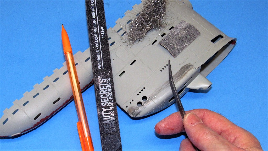
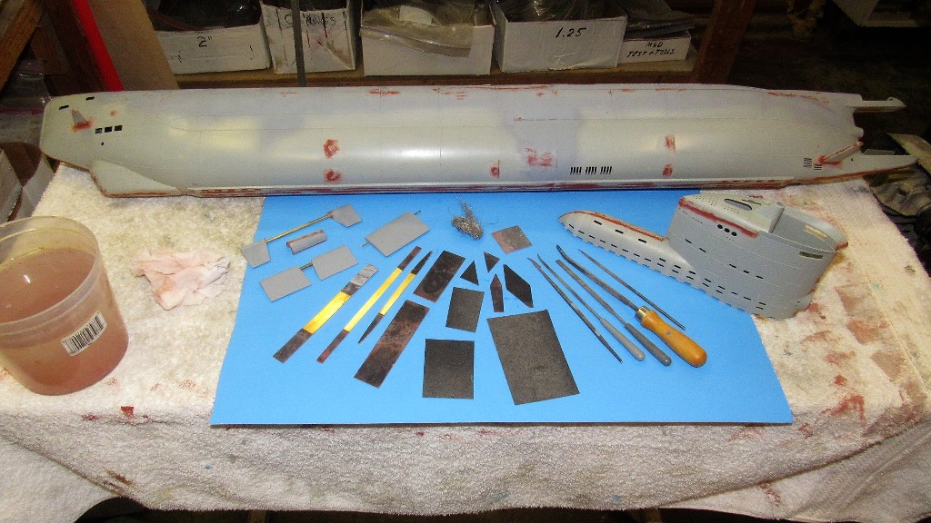
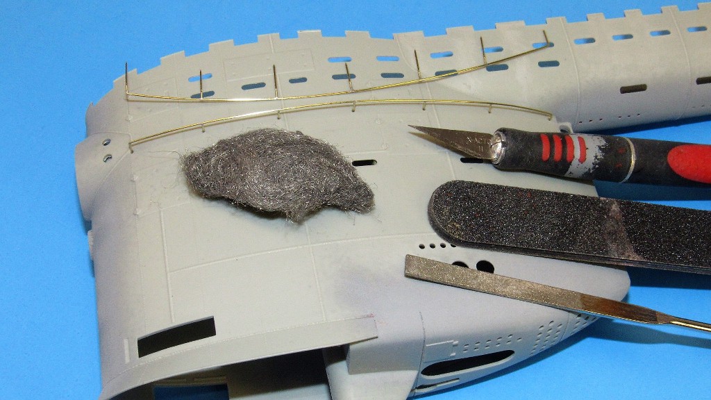
All filing and sanding over the touch-up putty was done wet. Here are the tools and the work. Special care had to be taken not to obliterate the many raised weld lines. This is a wonderfully detailed kit. Bronco got this one right!
For those hard-to-get-at spots on the model (and there were many!) I used special abrasion tools, such as these little metal-backed sanding tools. Grits ranged from #240-#400. The sandpaper glued to various widths of .014-inch-thick brass strip.
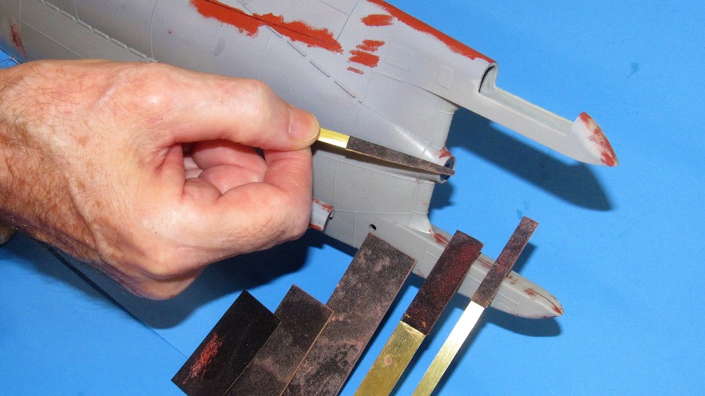
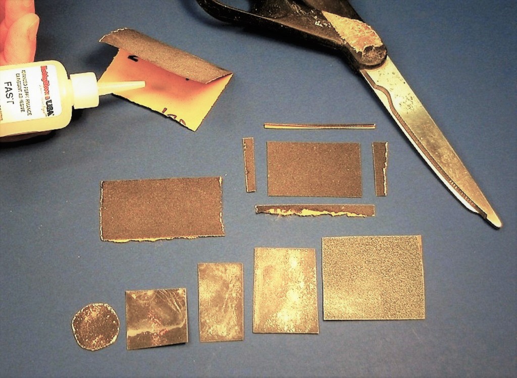
Another useful abrasion tool is double-backed sanding squares. Just fold a piece of sandpaper, slather some CA between the two halves, close and compress, and in no time, you have a very stiff, double-sided sanding tool. Just cut the tool to size and shape with scissors.
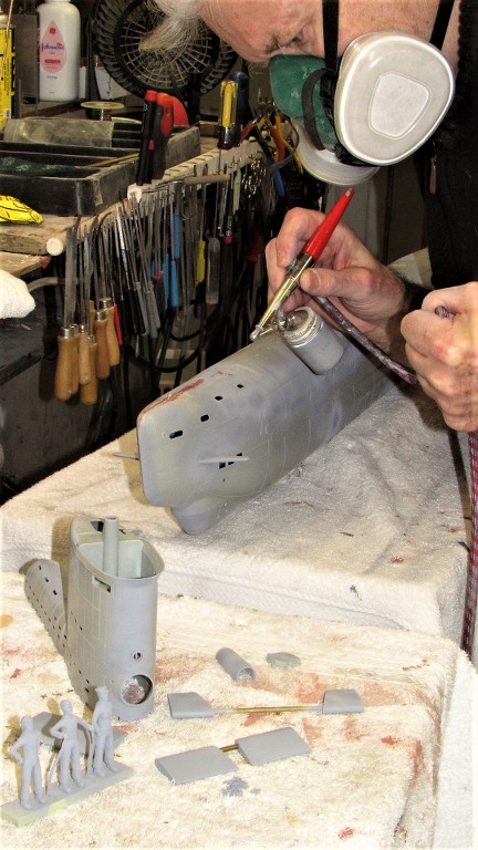
All sanding completed I spot primed the model parts.
This is my primary workstation. Note all the hand-tools hanging off magnets.
 Who is John Galt?
Comment
-
Having the right tool, and handy when its needed sure is the way to go!
Rob
"Firemen can stand the heat"Comment
-
The kit supplied plastic railing that girdle the sides of the sail are just too fragile to be serviceable on a practical r/c submarine. So, I substituted brass wire railings.
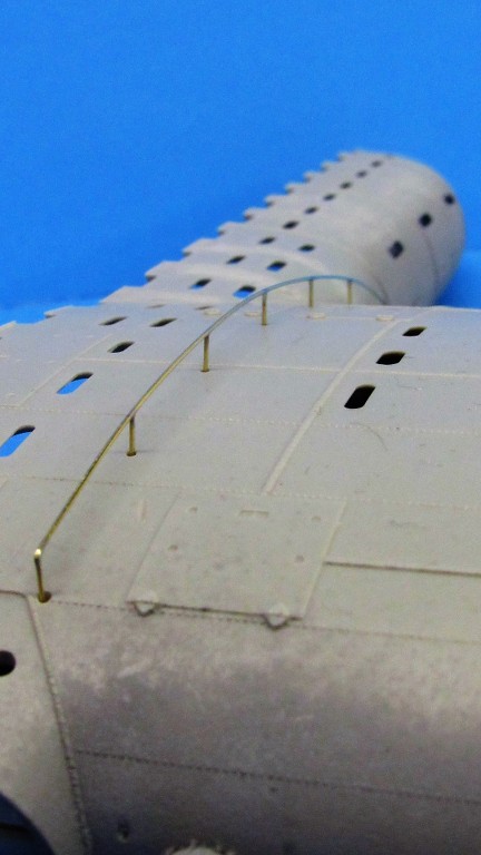
The two brass railing assemblies are formed of .020-inch diameter brass rod. The pins are about .375-inch long, pointed at the inboard end, and ground to a flat at the outboard end.
The RenShape pin-retainer, which temporarily resides within the sail -- and conforms to the curve there -- securely holds the embedded pins in place and also serves as a heat-sink to rapidly dissipate soldering heat away before the easily melted polystyrene plastic of the sail.
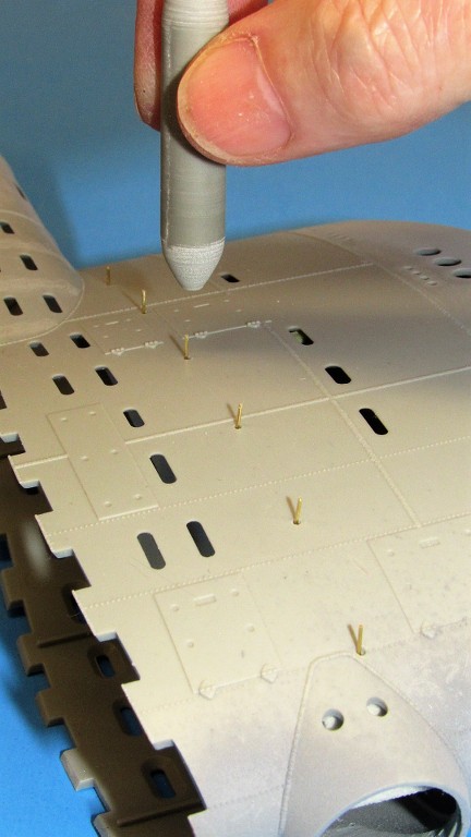
After the pin-retainer is installed within the sail (shown outside so you can see how it would be used) the bore clearing-pin setting tool is used to push a pin through one of the .023-inch holes that have been drilled through the side of the sail.
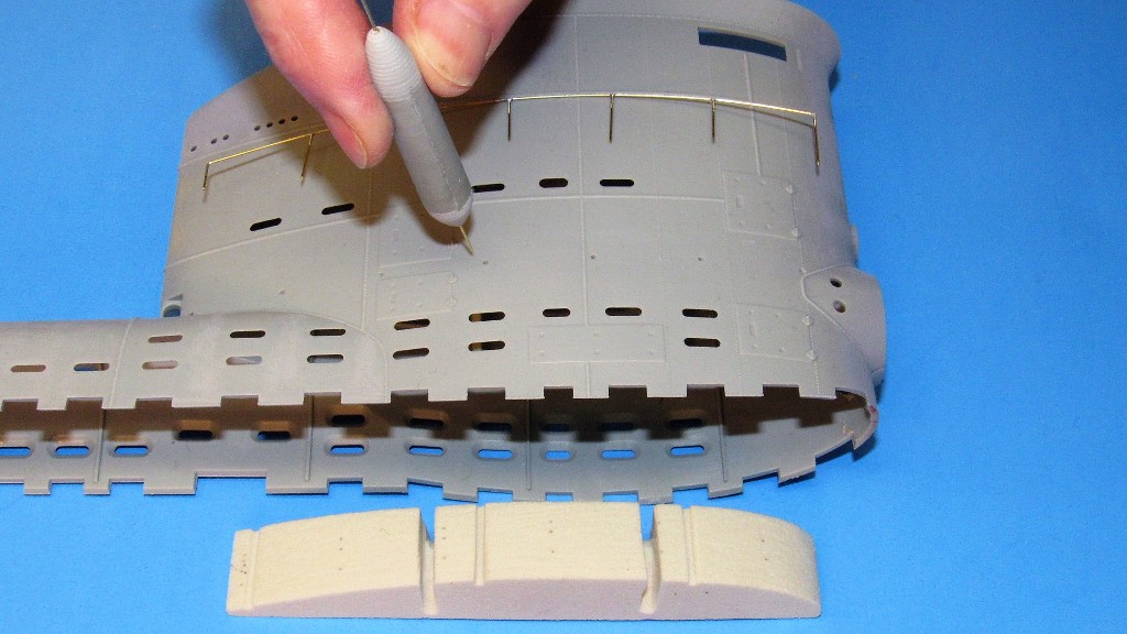
Pulling the bore clearing-pin setting tool away from the work leaves the pin well embedded into the pin-retainer bearing against the inside of the sail. Use of the tool results in an array of railing pins projecting from the side of the sail, all of the same height.
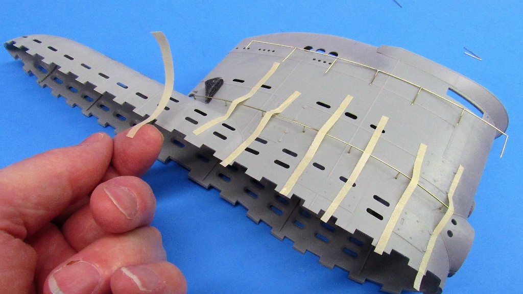
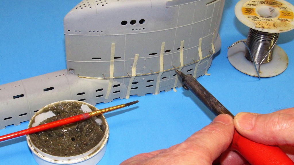
A long length of brass rod becomes the railing proper. Here I'm using thin strips of masking tape to secure the railing over its pins. Note the finished railing assembly laying near the top of the sail. With the aid of the internal pin retainer the sail itself becomes the holding fixture of the parts that, once soldered together, become a railing assembly.
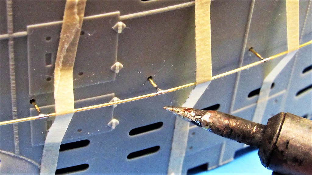
The secret to keeping the heat localized to the joint is a hot soldering iron tip; a tip that is ground small to minimize heat transfer to non-joint structures; and use of the pin-retainer which also acts as a heat-sink.
The tip of the iron is applied to the joint with half-second jabs, just long enough to get good solder flow, as evidenced by these small, tight fillets between rail and pin.
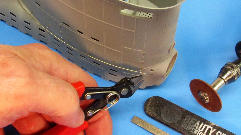
Snipping off the excess railing at the forward-most pin. The raw end here would be worked with file and sanding stick after contouring with very light, carefully applied jabs of the carbide cut-off wheel.
While still in place on the sail the railing assembly has all the solder unions cleaned up by scraping away excessive fillet with a blade; sanding and filing away solder and crystallized flux; and finally abrading away all scratch-marks with a good polishing using #0000 steel-wool.
After all soldering and clean-up work had been done on the railing assembly the RenShape pin-retainer, within the sail, was pried away from the pins and removed.
The pin-retainer is used as a handling fixture if any further work on a railing is required off-sail. Note the three items needed to do the soldering: a 35-Watt soldering iron with custom ground tip; acid paste flux; and 60/40 solder. At the bottom of this shot is the bore clearing-pin setting tool.

Who is John Galt?Comment
-
I like the way you did this David.
Difficult to tell in the pictures how you applied the solder.
What I do for delicate soldering like this is I slice a sliver of solder off of the spool with a Exacto blade. Usually a very tiny chunk, enough for the joint being soldered. Put some paste on the joint, put the tiny chunk of solder on the joint on the paste, then apply heat. The paste holds the solder in place. This minimizes there being a glob of solder on the joint that needs file cleanup if you were to feed solder in from the spool. And only applies the amount of solder that is necessary.Comment


Comment