
Mister, I been from here to there in this galaxy and I just want you to know you're the most understanding soul I ever met up with.
-
Of the approximately 40,000 men who served on U-boats in WWII, it is estimated that around 28,000 to 30,000 lost their lives. -
-
I forgot all about Cultman. I see he’s still in business. Good guy.Last edited by Das Boot; 12-31-2021, 10:15 PM.Of the approximately 40,000 men who served on U-boats in WWII, it is estimated that around 28,000 to 30,000 lost their lives.Comment
-
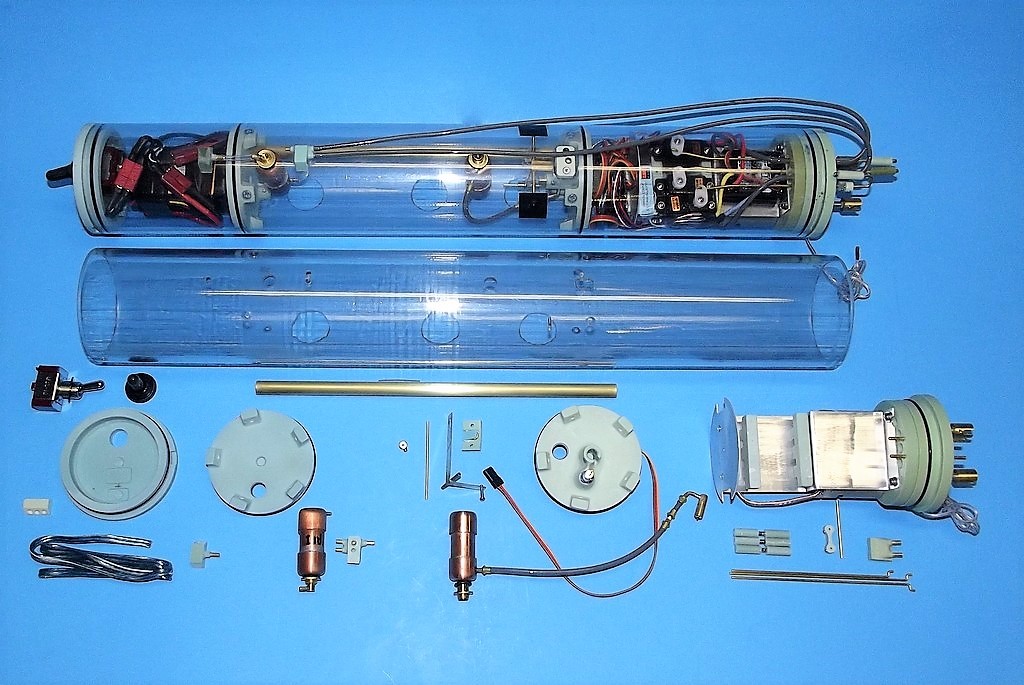
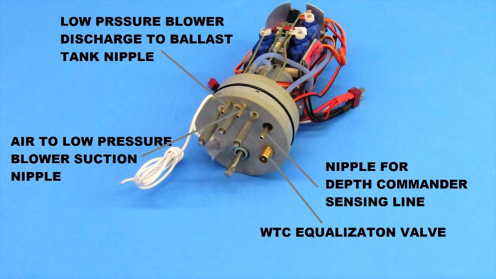
Representative of the type water tight cylinder (WTC) I produce is this shot of a completed unit. Below are the basic parts of a WTC.
So, back to the WTC I've built for Casey's 1/96 BLUEBACK model. Before populating his WTC with the devices, I sat each one on the table and went through the set-up protocols outlined in the instructions that accompanied each device. Better to do this off WTC than in it... because things NEVER go right the first time you go through a set-up routine! No matter how well written the instructions are. And KLM instructions are the best I've seen written in the English language.
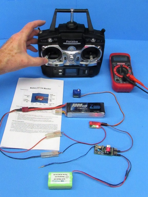
The first devices to be set-up and certified operational were those that required connection to the power bus.
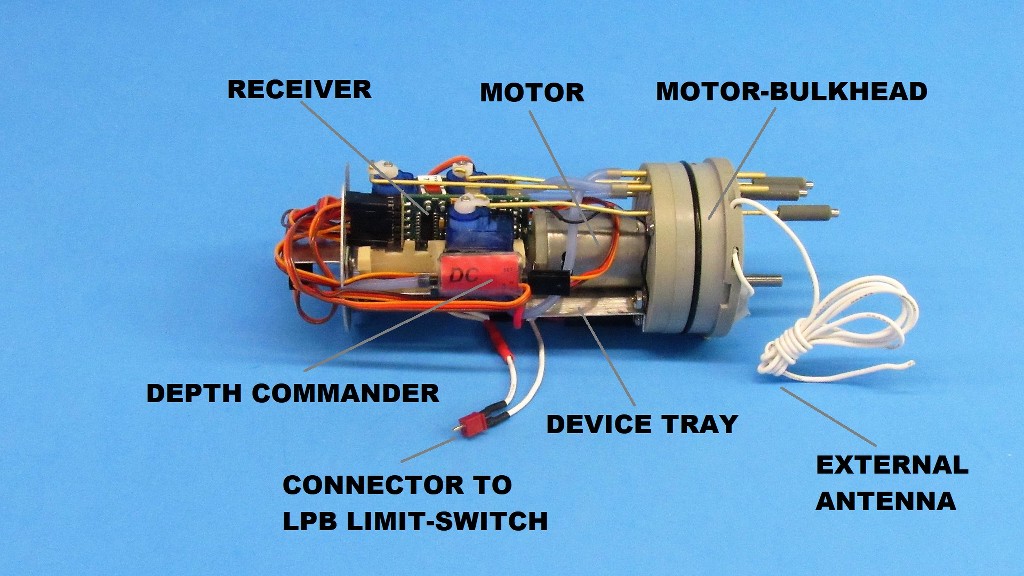
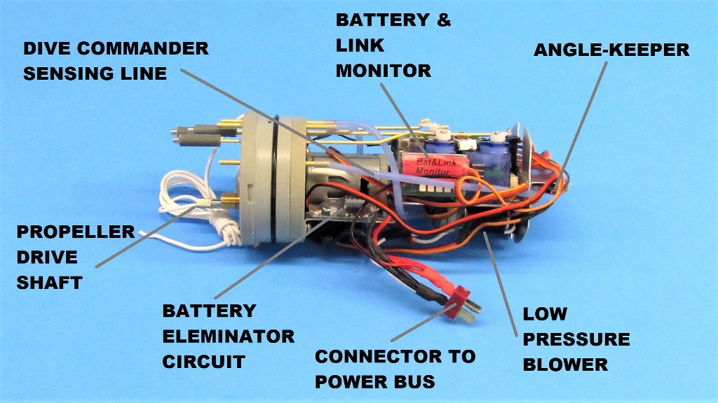
Certified in good working order, these devices were attached to the motor-bulkhead mounted aluminum device tray and bulkhead with the aid of double-backed servo tape. Those items included the low pressure blower (LPB), battery eliminator circuit (BEC), battery & link monitor (BLM), and electronic speed controller (ESC). The input power wires of these devices were all ganged together in parallel and soldered to a male Deans plug. Later, power cables from the forward dry space battery would run aft, terminating in a female Deans plug.
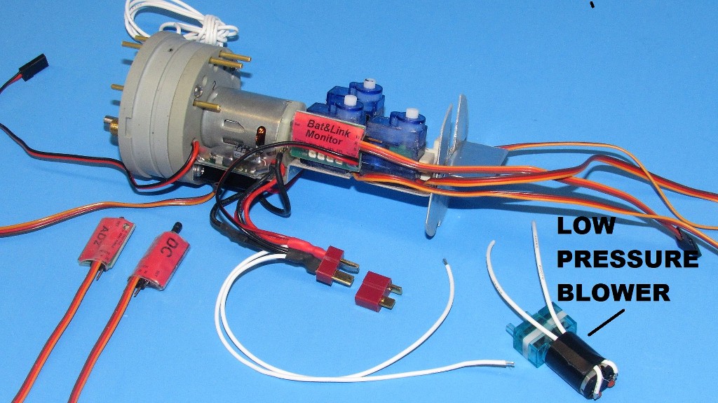
The devices, all mounted to the motor-bulkhead, require only three plugs to interface with the rest of the WTC: The big power bus Deans connector just described, a small Deans connector between the LPB motor and ballast servo limit-switch, and the J-plug of the ballast servo itself. Use of these three connectors make installation/removal of the motor-bulkhead assembly from the cylinder a quick, and easy procedure.
Here I'm soldering the wires to a small Deans plug that makes up to the ballast servo limit-switch. The other half of the little Deans connector has already been made up to the LPB and power bus.
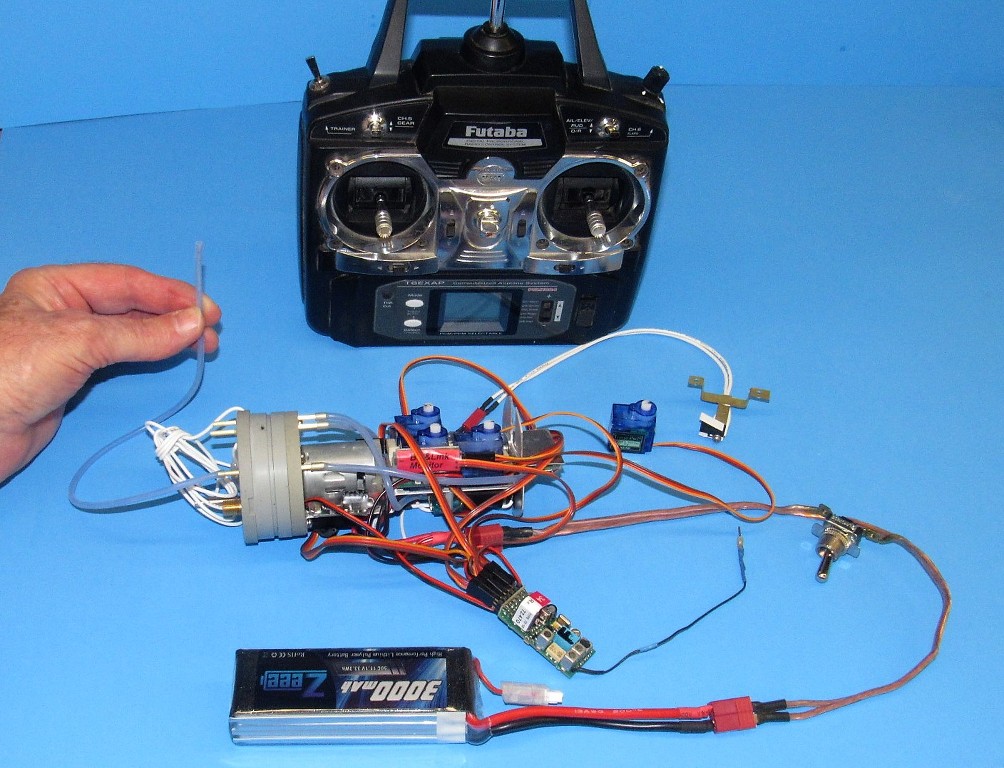
Casey wanted the KLM Depth Commander (DC) device installed. Here I'm verifying the sensitivity of this hydro-statically sensitive device with a column of water in that little hose I'm holding.
I found that the device will deflect the bow plane servo in the required direction with only an 1/8-inch variance in water height. Wow!
This device will automatically hold the submerged model submarine to a specific ordered depth. I've been using these depth-controllers for a couple of years now and found that they greatly reduce operator work-load when driving the model around submerged -- all you gotta do with this thing on line is steer and manage the throttle... if only it could cook!
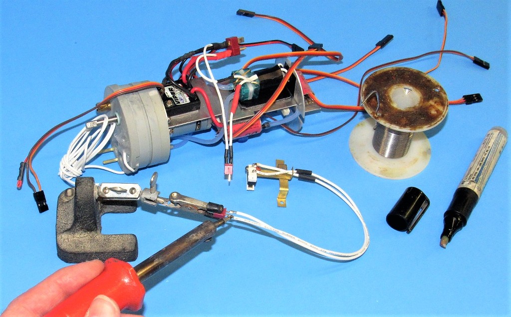
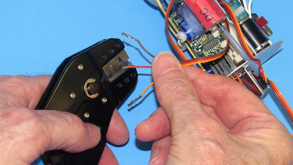
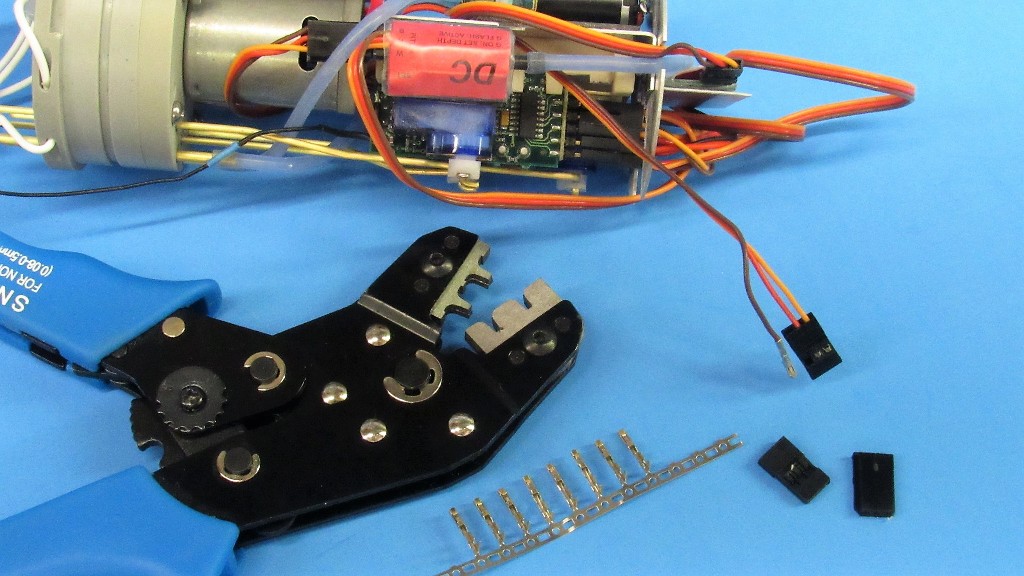
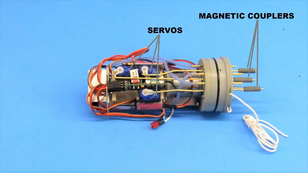
In the very tight confines of the after dry space of the WTC one must make every effort to reduce the wire runs. Such is the case with the device three-wire leads (servos, DC, ESC, BLM, and angle-keeper). There was way too much slack in these wires, so I cut them short and crimped on new female pins designed to slip into standardized J type Futaba connectors.
Here you see discarded leads. Note the tight packaging of devices and short runs of their leads once everything had been tightened up. Good house-keeping is a virtue in this game.

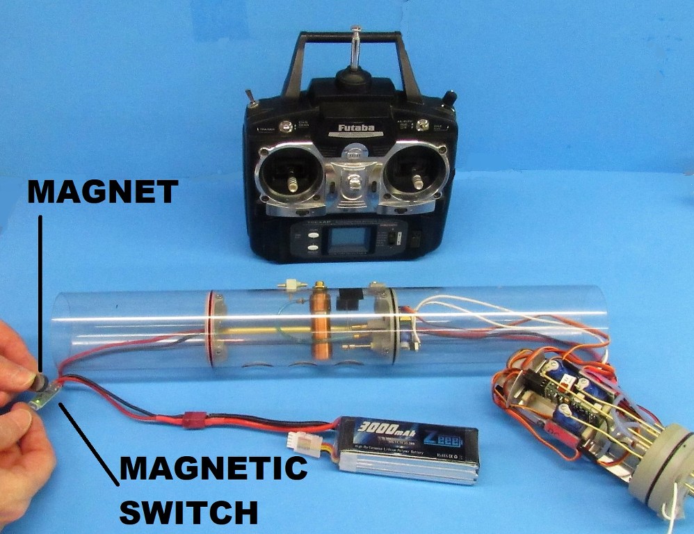
The power bus is switched on-and-off by a magnetically actuated switch. Yet another KLM device. Here I'm making up the input and output wires to this little device. This switch is situated in series between the Lithium-polymer battery and power bus.
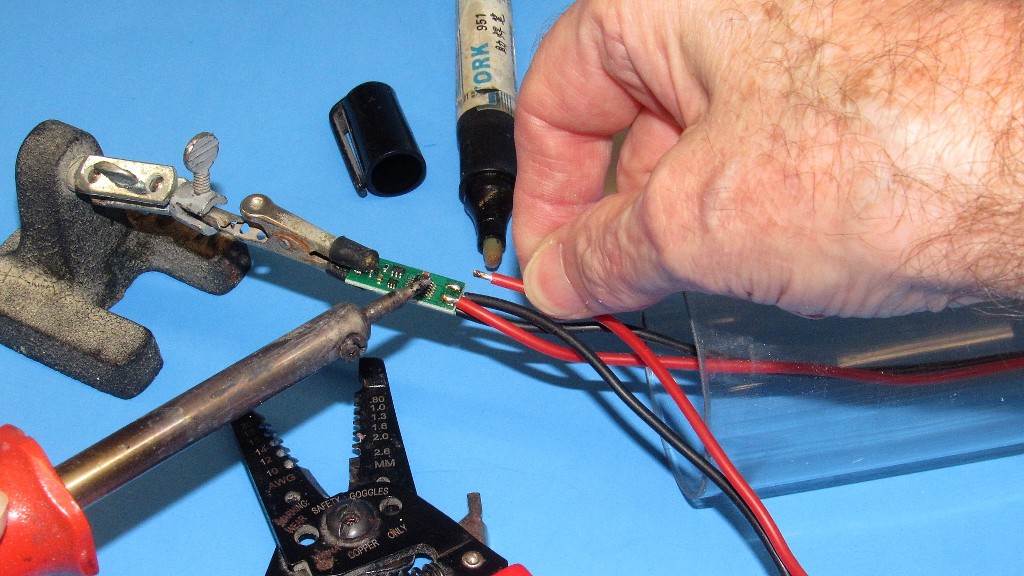
Just wave a magnet over the switch and power is delivered down the power bus to the motor-bulkhead devices. Wave the magnet again, and power is secured. Slick!
The gory details:
 Who is John Galt?
Comment
-
Talk about putting10 lbs. of crap in a 2 lb. bag! Never thought of cutting the leads. That is a space saver and solves a problem I had with the MSD as far as space. Nice work for a curmudgeon.Of the approximately 40,000 men who served on U-boats in WWII, it is estimated that around 28,000 to 30,000 lost their lives.Comment
-
You're gonna love this thing, Casey. Tonight, I'm fine tuning the fill-sand-prim routine on the hull and control surfaces, getting those items to a flawless primer gray surface for you. Might even find time tonight to mount the WTC and start in on the linkages. The rest will be on you... you old, foul tempered fart.
DavidWho is John Galt?Comment
-
Nice clean well thought out work. No rats nest cluster **** of wires and easy to work on. Well done Sir.Comment
-
When I get the boat, I’ll get my trusty contour gauge, take a mold of the hull, and build a stand. Then work on the scribing, flood holes and paint. Then weights and floatation.Of the approximately 40,000 men who served on U-boats in WWII, it is estimated that around 28,000 to 30,000 lost their lives.Comment
-
With the WTC up and running (but not yet leak checked and suffering a yet to be determined servo chatter during a loss-of-signal event) I returned to the 1/96 BLUEBACK hull chores for a last round before integrating WTC and hull.
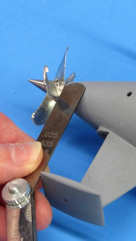
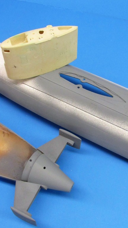
The hull parts again front and center I had found that the end of the tail-cone was a slightly smaller diameter than the propeller hub, which would necessitate a build-up of the stern diameter to match the propeller hub. Poor planning! I should have caught this before getting the tail-cone into primer gray. I got rushed. Stupid!
The end diameter was about .050-inch shy of that of the forward face of the propeller hub. Damn! Had to fix that.
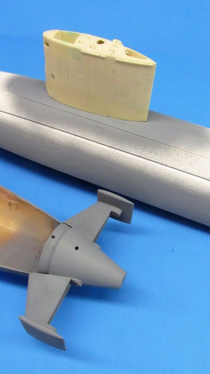
And -- as the sail sat within a shallow well built into the deck of the upper hull -- during a test-fit I observed that there were significant gaps between the sides of the sail and the vertical walls of the well. That would have to be fixed as well. Another job for Mr. Bondo. I love that stuff.

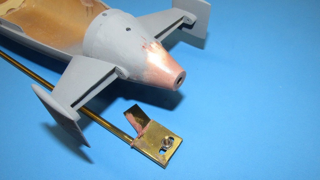
Before slogging through all the muck, here's the end-game of this post:
A properly shaped tail-cone-to-propeller hub contour; and a tight, gap free, fit of the sails base within the shallow well of the upper hull. Looks nice, huh? Well... the getting there is the hard part, pal! On to the gory details.
There were many little pin-hole voids in the leading edge of the tail-cone horizontal stabilizers and leading edges of the vertical stabilizers. These were filled with CA adhesive and baking soda sprinkled on to form a quick setting, hard 'grout' that was then worked to contour with careful use of a small flat file. Those areas were then given a light brush-coat of Nitro-Stan touch-up putty. While brushing on the putty I also addressed some areas where tool-marks were still evident in spite of the heavy primer coat previously sprayed on.
At this point in the project I was still blissfully clueless of the too-small diameter at the end of the tail-cone. THAT should have been the first thing I identified before all the fill and putty work. What a dumb-ass... I'm supposed to be good at this ****.
When sanding simple curves on a uniform substrate, I make use of a stiff sanding tool formed from a brass strip outfitted with sandpaper on both faces. #400 grit on one face, #220 on the other. Here I'm wet sanding the putty.
Typically, I'll use a 'soft' sanding block when working a compound curve, like this union between the GRP lower hull and resin tail-cone. But here I'm using the stiff sanding tool. This because there are four different substrates being ground away, each of varying hardness to the other: GRP gel-coat of the lower hull; polyurethane resin of the tail-cone; soft touch-up putty; and hard CA at the hull and tail-cone union.
A soft sanding block would permit the backed-up sandpaper to flex into soft mediums, cutting too much, but ride over the hard mediums, with little cut. The result would be dips where the soft stuff is and bumps where the hard stuff resides. A stiff sanding block won't have any of that! It cuts to a straight plane regardless of substrate hardness.
Hence my use of the hard-backed sanding tools at the tail-cone-to hull interface point. But, later, once I'm just working primer, that's when I fine tune such areas with a soft block.

I use an adjustable radial screeding blade to build-up the diameter of a tail-cone. Not much to it: A pin that fits the bore of the stern tube, and a blade that can be set in diameter and angle to develop the required diameter and taper angle -- that new diameter the same as the forward face of the propeller hub.
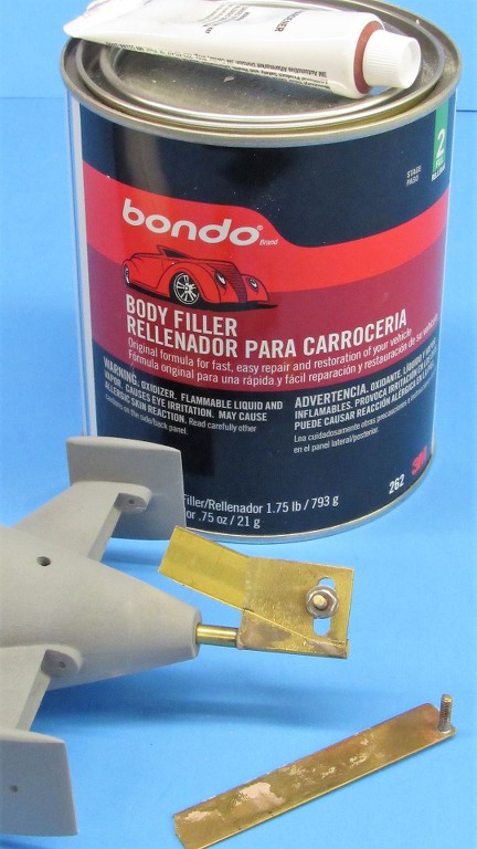
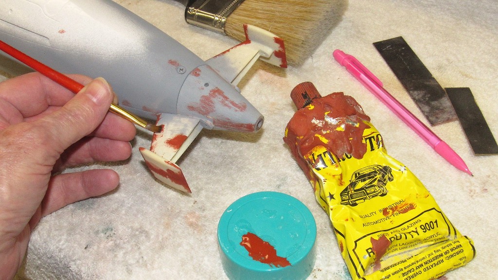
Radial screeding is simple. Set up the screeding blade angle and diameter, slather on some Bondo to the ass end of the tail-cone, and rotate the tool by hand. It takes about three cycles to get all areas of the stern re-built like this, but total work time is less than ten-minutes. Bondo is our friend.
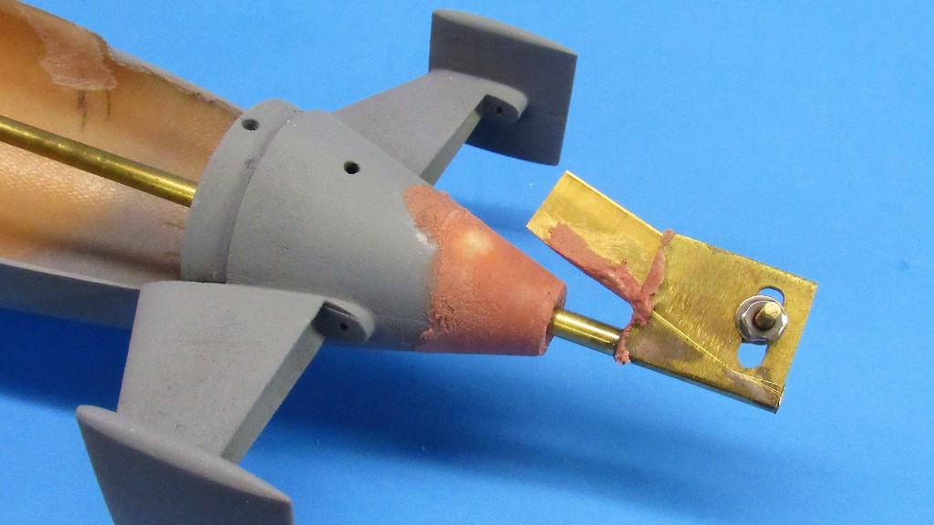
After some touch-up work with flat file and sanding block the Bondo areas are coated with a layer of CA adhesive. This fills and strengthens the otherwise porous Bondo. Another wet sanding and the re-contoured tail-cone is ready for primer (again!).
The sail initially sat with a pronounced lean to port when test fitted. That had to be fixed. Here you see the re-worded well corrected to both mount the sail perpendicular to the hull and tightened up to show only the barest of gaps between sail and well.
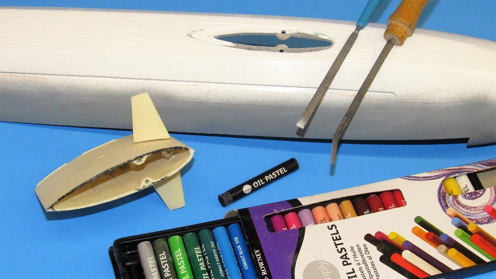
Within the well that accommodates the bas of the sail you can just make out the hash-marked area I'm going to cut out. Three reasons: first is that you want to take every opportunity to reduce the above waterline structures that would otherwise displace water -- the lower the displacement, the less ballast tank you need to assume submerged trim; second reason is that I need access into the hollow sail in which to pass the pushrod that operates the sail-planes; and third, this opening will quickly vent air and water in and out from within the hull and sail as the boat transitions between submerged and surfaced trim.
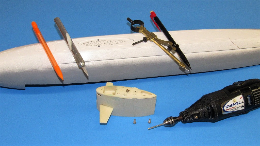
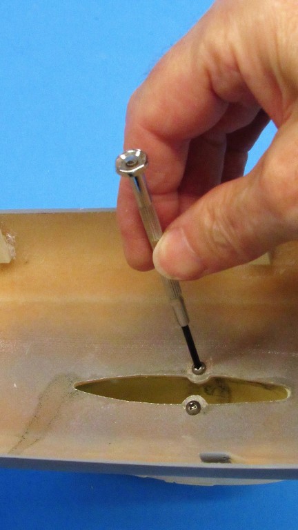
Using a standard 1/16-inch drill bit in a high-speed hand-tool I free-handed the bit within the outline -- a poor mans milling bit. The work went quicker and with more precision and speed than would have been the case had I done the work with a cut-off wheel and carbide burrs.
Note that only two machine screws, run up from within the upper hull, are used to secure the sail atop the upper hull. Whenever possible I make as many sub-assemblies removable in order to facilitate later repair, adjustment, or maintenance. The philosophy obviously shared by the kits designer, David Manley.

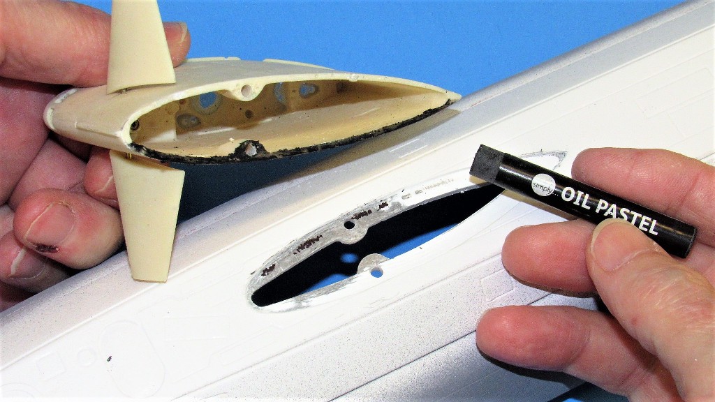
Initial dry-fitting of the sail atop the hull revealed that it sat canted several degrees from vertical; it was leaning to port. The solution was to lower the starboard side of the wells base to bring the sail into proper alignment. Where to shave? How to identify the 'high' spots? That was solved by coating the base of the sails starboard side with sticky, messy, gets-everywhere-you-don't-want-it oil based crayon.
The crayon black is smeared to the starboard bottom of the sail, the sail pushed down into the well, lifted out, and the high-spots picked out by the black smearing.
I went mid-evil with chisel and files.
The smear-chisel-check cycle repeated till the sail sat perpendicular to the hull.
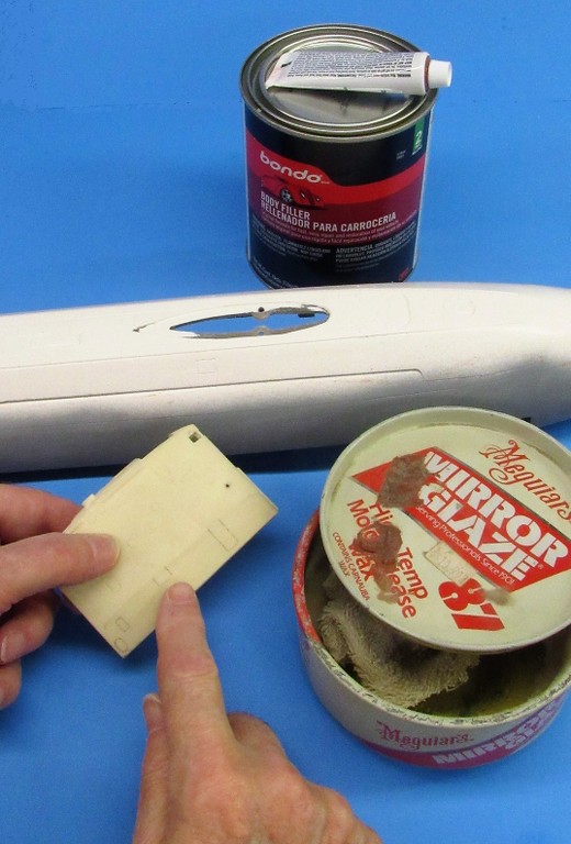
As I only wanted Bondo to stick to the walls of the well I applied wax to the bottom end of the sail. Giving the wax an hour to harden, the sail was then set in place and secured tight with the two machine screws.
Only two 2-56 machine screws are required to hold the removable sail atop the upper hull.
I must say, David Manley, who is the guy who designed and produced this kit so long ago is still teaching me and guys like me new tricks. Just by working one of his kits the observant model kit-assembler can learn a lot about functional design and appropriate materials selection. I have stolen his ideas shamelessly and incorporate them into my own work whenever the opportunity presents itself.
Every aspect of the model-building Craft has its 'experts'. Off the top of my rather pointy-head let me rattle off a few of these dudes who have contributed so much to the Craft:
Those interested in static/display model aircraft (a more savage collection of anal-retentive, rivet-counters, and know-it-all's cannot be found) have guys like Ben Guenther (an alarmingly calm, gracious, and most helpful man); The static/display model car perfectionists have the unassailable icon of Gerald Wingrove; the model rocket egg-heads have the prolific Scott Lowther and Mat Irvin; the SF vehicle tin-hats have Martin Bower and David Sisson; the model ship guys have William Blackmore and August F. Crabtree; and we lowly r/c model submarine guys have our own David Manley, Matt Thor, Greg Sharp, Dan Kachur, and Robert Dimmack.
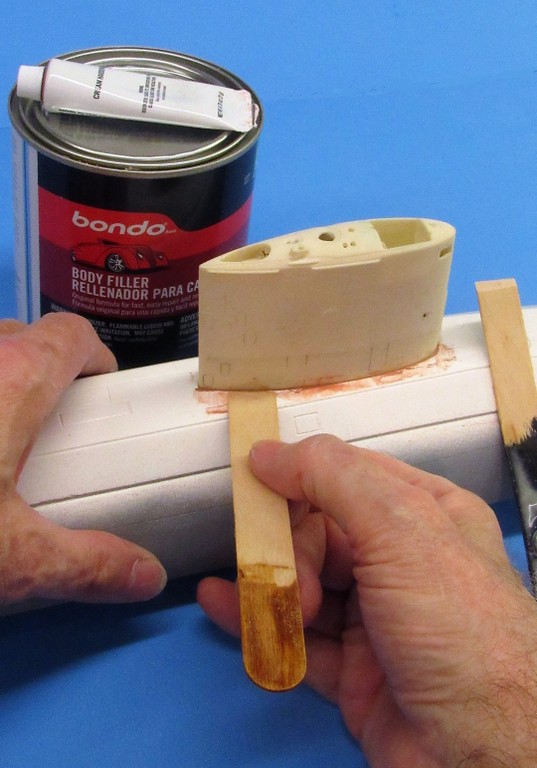
The sail secured to the upper hull I mixed up several small batches of catalyzed Bondo. Done in stages as the stuff cures quickly. The time it takes to do this job way exceeds the useful working time of this stuff if attempted in one cycle. The objective is to jam and force the Bondo into the voids between sail and sides of the well. The Bondo will... hopefully... stick to the sides of the well, but not stick to the sail.
Wooden putty-knifes were fashioned from tongue-depressors -- wood because a metal putty-knife would scrap away wax from the sail, leading to sticking of the Bondo to that structure. Something to be avoided.
Once the sail was popped off the well (no problems encountered), the wax was scrubbed off by a lacquer saturated abrasive sponge.
 Who is John Galt?
Comment
-
There are many special interest groups (SIG) within the general hobby of radio controlled vehicles. Aircraft, be they fixed wing, helicopters, quad's, and blimps; cars and other wheeled ground vehicles; boats; robots; submarines; and a few other type vehicles -- they all require an operator in the control-loop, guiding the vehicle, sometimes at a great distance, through direct observation.
Hobby vehicle drivers have wanted the ability to shift their perspective from
their physical location to a view presented to them remotely from the vehicle itself; putting them, virtually, in the driver's seat, able to view the world from the vehicle itself rather than observation of the vehicle from a distance -- to see what the vehicle sees and control it from that perspective as though the driver himself was aboard the vehicle.
Today, hobby first person view (FPV) equipment is available, and we have the Juggernaut of the r/c model airplane community to thank for that. The fliers: those guys, tens of thousands of 'em, assured inventors, investors, and manufacturers that a market existed; a market large enough to warrant the effort.
Our very small group of r/c submarine drivers can now dine on the table-scraps of the airplane and drone guys; their win is our win. That gear is now available to us.
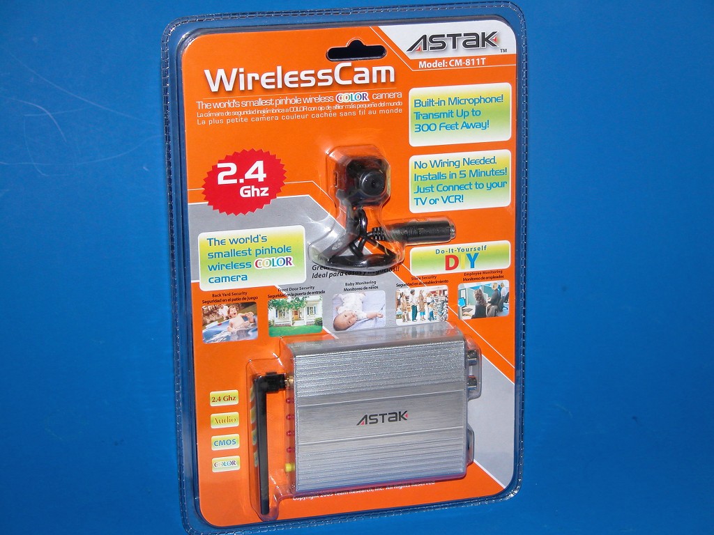
FPV equipment became a reality to the general public about the turn of this century with the availability of basic, low quality (by today's standards) camera-transmitters and virtual goggles. The intended market was those people interested in Home Security.
Over time advancements in picture quality, range, size and weight reduction, and standardization within the r/c hobby industry matured the equipment to the point where, today, a system can be bought at a very reasonable price and easily placed aboard the r/c model and put to work with little fuse or technical expertise.
Things started to ramp up for me in the FPV department when Walmart began selling these small, cheap camera-transmitter units, complete with ground-station receiver. This was my entry-level toy to the world of FPV as applied to r/c model submarines. That was about fifteen years ago.
By today's standard the image quality was bad -- these were the days before camcorders, cellphones, and dedicated video cameras went from 'standard' to high-definition (HD) quality imagery. But, for the time, the image was good enough if you really wanted that, I'm aboard the model experience.
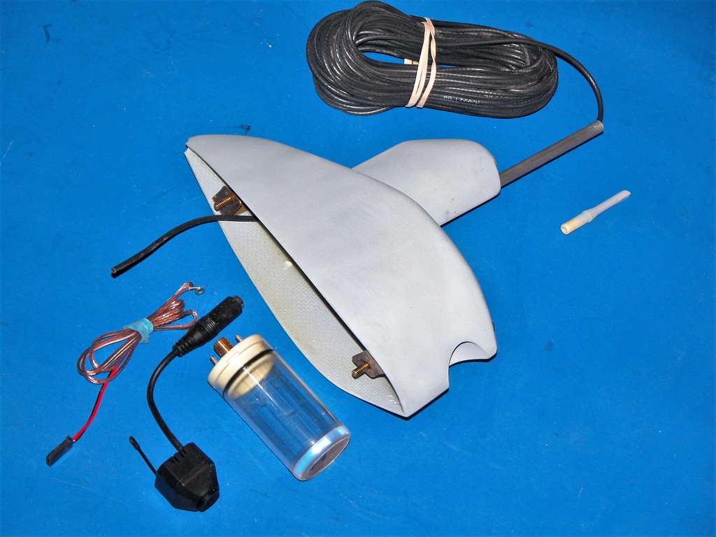
The little Swann camera-transmitter unit, other than the power supply, was all inclusive. Only two modifications were required: first was to relocate the transmitting antenna via a shielded coaxial cable up to a position high atop the models sail, where it could project above the water as the model ran at periscope depth. This necessary as the high frequencies (typically in the 2-5gHz range) will not punch through water.
The second requirement was to install a voltage regulator between a 9-volt battery I recommended at the time and the camera-transmitter which typically dinned on 5-volts.
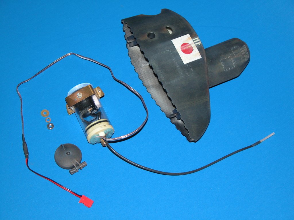
With these two relatively simply modifications the unit would fit within a 1.25-inch diameter acrylic cylinder outfitted with a clear lens forward and a streamlined after access cap at the stern. Atop this watertight enclosure was an antenna interface piece that mounted a streamlined aluminum fairing through which the coaxial cable passed, terminating topside in the 1.25-inch long 2.4gHz transmitter antenna.
Ellie and I produced the 'up periscope' watertight enclosure and made it available for sale during our tenure with the Caswell company. Market acceptance was, to be kind, awful!
Was it something I said?...

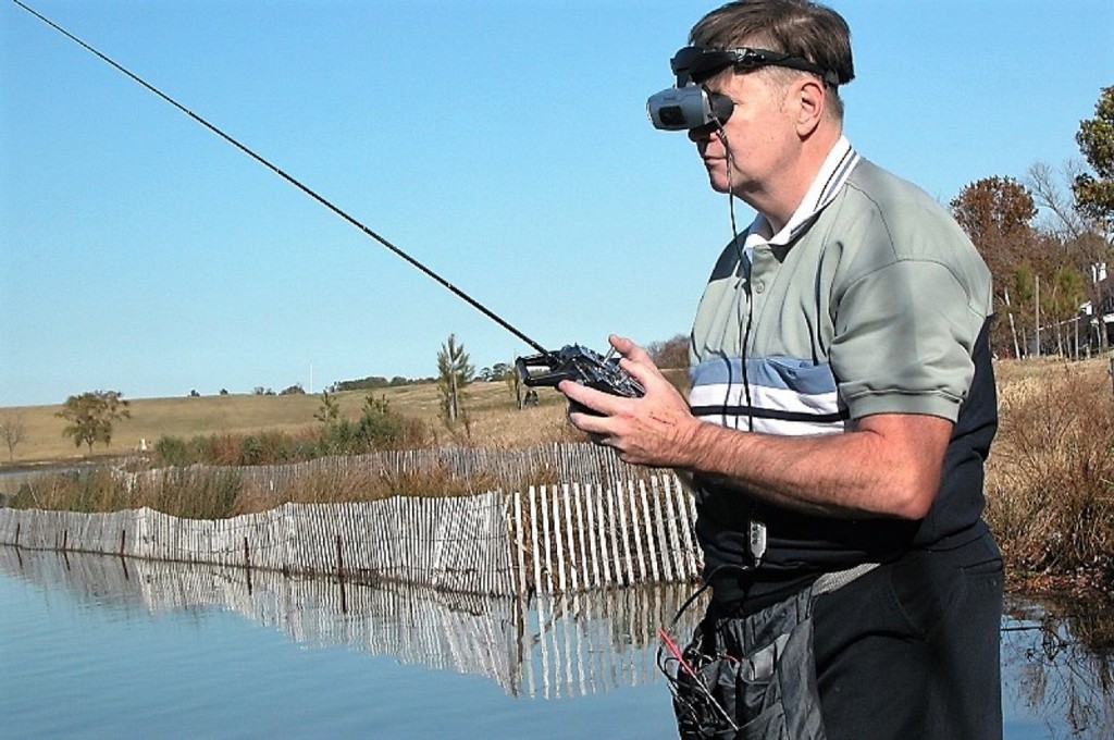
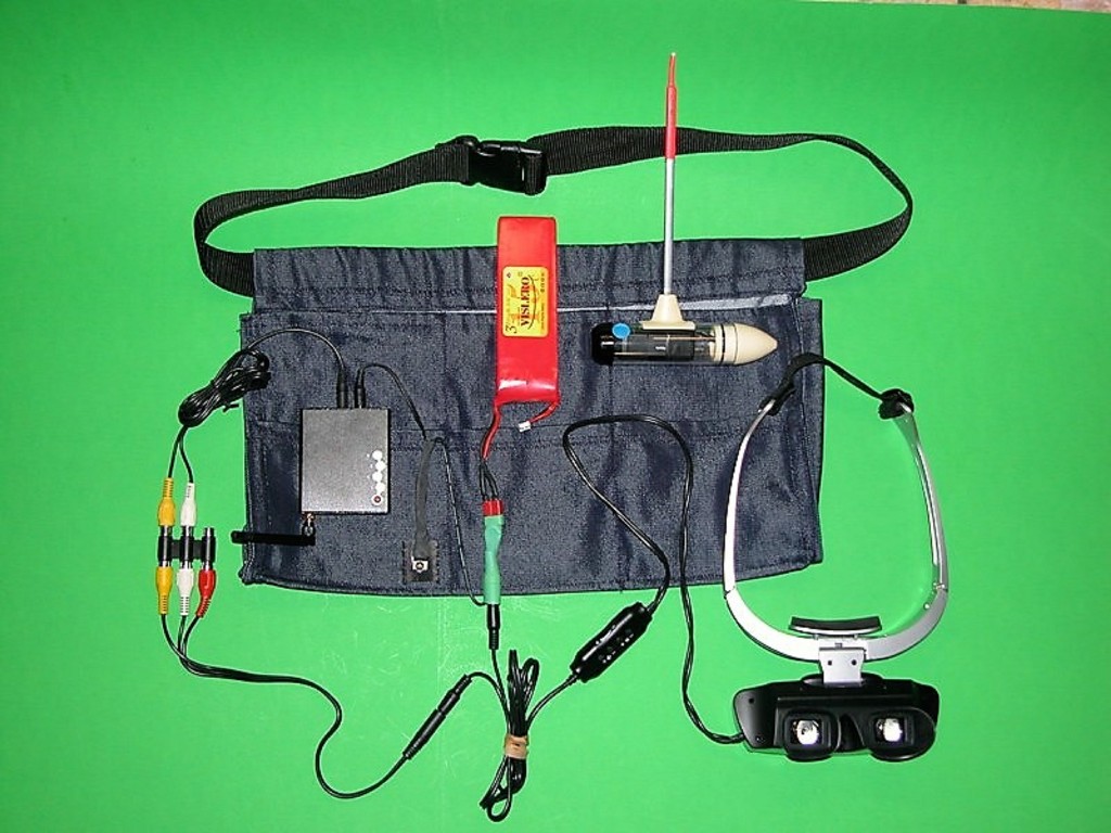
This was around 2007 and the associated virtual goggles, through which are projected the camera images into the eyes of the far distant driver, are nothing like what is common today: They was just two low resolution LCD's, one for each eye. Fuzzy. And the power supply had to be jacked into the goggles. Hence the need for this Batman utility belt my kid's wife sewed up for me -- just to hold all the gear needed to make me a walking, silly looking, 'ground-station'. (A tin-foil hat would have completed the look of a well-dressed techno-nerd).
The word, cumbersome, comes to mind about my early effort at FPV. But it worked. Not well by today's standard, but it was a thrill to finally drive a model submarine as though I was right there, in the water. One time, in a chop and trying to maintain periscope depth, I puked all over my pants -- it's that immersive! I've always had poor sea-legs.
All this as preamble to the gear offered today. Things have matured: the goggles now are consolidated with the other ground-station devices. The virtual goggles contain the OLED screen(s), receiver and antenna, audio output, power supply, and ability to scan the accepted bands and frequencies making matching of camera-transmitter and ground-station a simple operation. And somewhere along this road of evolution, picture quality went from 'standard' to 'high-definition'.
Below is 'old school' ground-station devices and utility belt. No more! To the Bat-Cave!
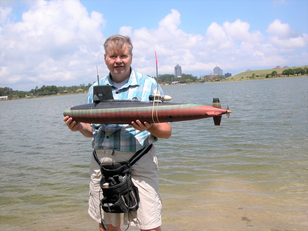
And what kind of r/c submarine is suitable for use of FPV? As the above photos illustrate, any model large enough for you to mount the watertight enclosure atop its hull or sail is a candidate for the system.
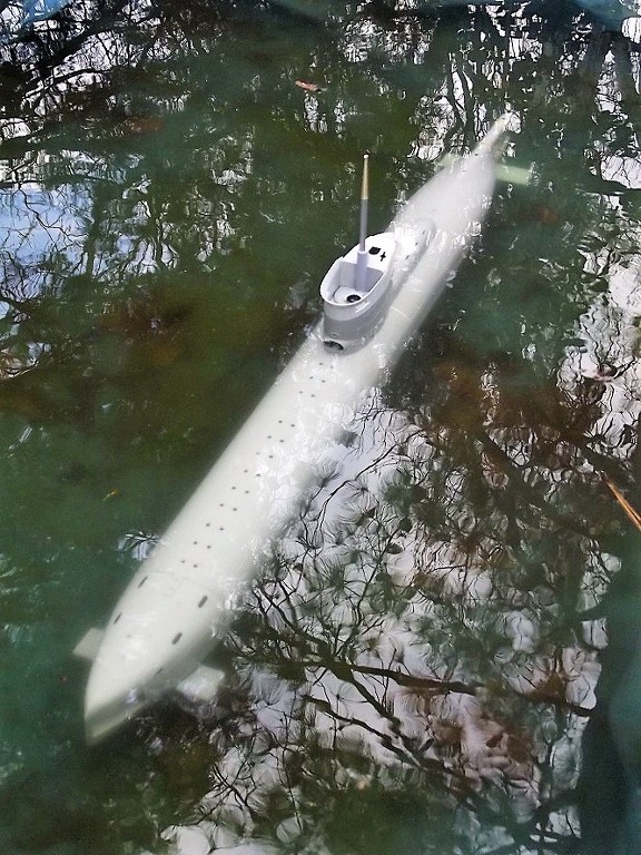
But for you purists like me, there are prototype submarines that have features that, without spoiling the look or hydrodynamics of the vehicle, lend themselves to internal camera-transmitters. I submit two fine examples: The 1/12 Williams Models, Japanese KAIRYU suicide submarine, and the 1/35 Bronco, German Type-23 coastal submarine. Both have a substantial 'opening' in the leading edge of their rather large sails from which a camera lens can peek out.
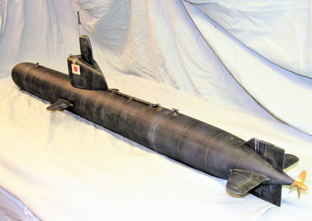
You can see my KAIRYU running submerged while towing a video camera here: https://youtu.be/em5--spYYnM and here, https://youtu.be/H4q1NO_IQGk (from 54:45 on)
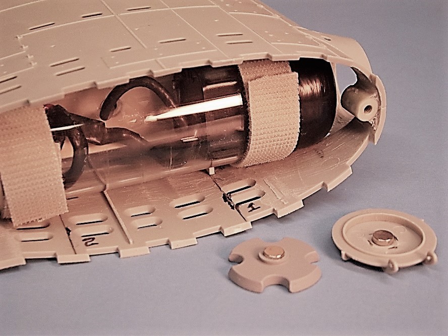
I've built two of these models, this one, for me, was initially set up with a Swann type camera-transmitter set into a short watertight enclosure small enough to fit within the sail, its lens looking out the observers deadlight that was a feature of some of these little submarines developed to ward off amphibious invasions of the Home Islands. Two winks of God's eye negated any need for their use... thank you very much, Mr. Atom.
At this early stage of integration, I was planning on utilizing a long coaxial cable, attached to a float, permitting unrestricted maneuvering in depth. But, quickly abandoned this rather ugly approach to the simpler and more scale like, antenna-within-a-periscope approach.
A floating antenna is too juicy a target for racing hydro's and other fast boats. No thank you.
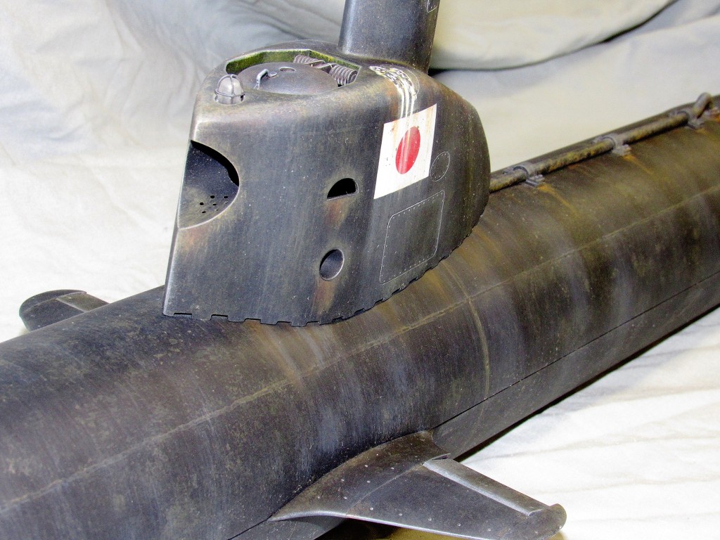
And here is the eventual arrangement: the antenna residing within the RF transparent hollow resin periscope head. It worked, but I quickly grew tired of squinting at the fuzzy picture presented me by the limitations of standard quality video which was only available during those early years of FPV.
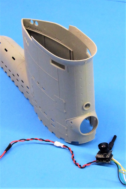
I made a similar packaging of the Swann system for one of my 1/35 Bronco Type-23's, but never got it past the testing stage due to the poor performance of the same type camera-transmitter and ground-station used with the KAIRYU. Note how on this class of boat the camera lens looks out through the temporarily removed line-locker stowage canister door. Perfect!
The video worked, but never used operationally on this model. Arrangement was very much like that aboard the KAIRYU: coaxial cable leading up within the periscope tube, terminating in the antenna within a hollow resin periscope head.
It took over a decade later, but when the high-definition, even smaller camera-transmitter units became available did my interest in FPV operation of submerged r/c submarines flicker on again.
Now we're cooking!
I just received proper VR Goggles, with all the trimmings. And a companion camera-transmitter. They have been tested and worked right out of the box. I opted for the cheap goggles, so video quality is below HD, but much improved over the Swann type cameras I played with in the past.
When I get this set operational and tested in some clear pool water I'll decide if it's worth it to purchase a top-of-the-line VR goggles, like the $500.00 Fat Shark ground-station that is so the rage among the r/c fliers these days.
We'll see.
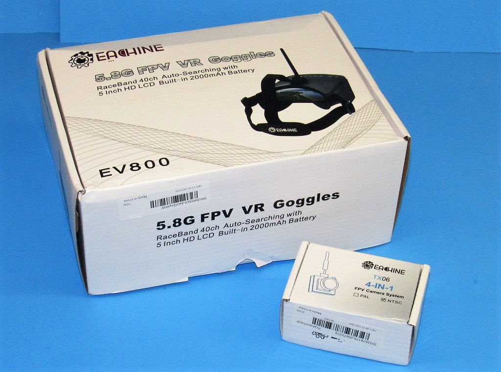
This basic, cheap, ground-station is fine for a guy just getting out of the stone-age, like me. Only cost about $70.00, but still is better than the old 'standard' quality video I got from the old Swann systems. And this ground-station is an all-in-one package. No more Batman utility belt required! The camera-transmitter could not be simpler: plug in a coaxial cable between the transmitter and antenna, run power to it from a 5-volt source, and you're good to go!

Nothing to getting both the camera-transmitter unit and power supply into a watertight enclosure and secured within the sail of the KAIRYOU and Type-23.
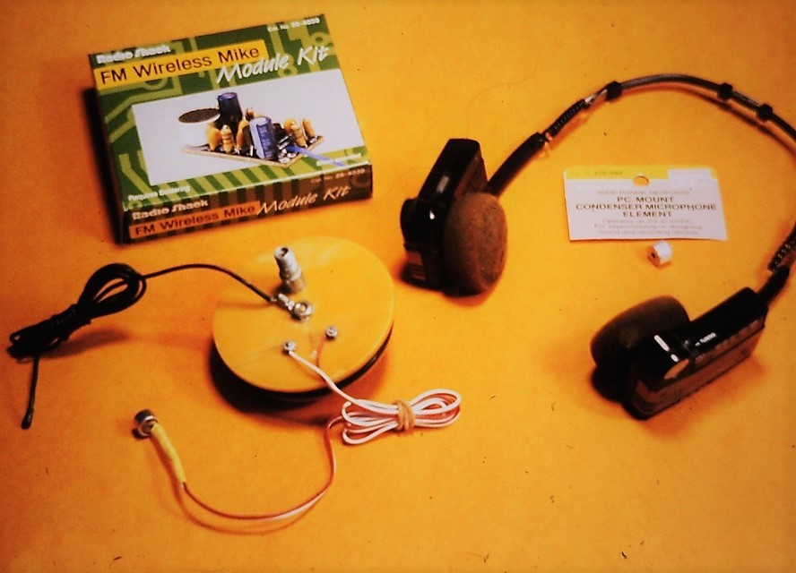
In the mid-90's I conducted my first practical experiments in receiving, from a submerged model submarine, intelligent RF energy converted to audio by a simple ground-station: an AM radio receiver. WA-La! Passive sonar.
I purchased a low-power AM audio transmitter kit, put it together, crammed it into the forward dry space of our just introduced WTC-3. Turning the thing on, driving the boat out a few feet at Lake Trashmore, then sitting the model submarine down in the muck. I tuned the AM radio head-set (my ground-station) to the transmitted signal and presto! I could hear what the submerged hydrophone was picking up. Boy... was it noisy down there, the Elite fleet had several boats in the water at the time and I could hear everyone except the sailboats (unless a sail-winch was in use).
Amazing! I could hear the over-head model boats running over or near my boats position. In time I could, just by sound, classify each type of model boat. Passive sonar, but without the ability to point at a source to get a bearing. Useless, but fun.
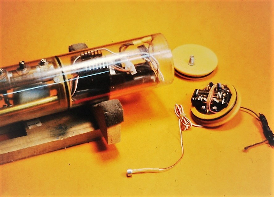
The entire 'sonar package', including its power supply, neatly fit into the cavity of the removable WTC forward bulkhead. The microphone was protected by a silicon oil filled condom and placed in the upper annual space between hull and the WTC's cylinder. Instant hydrophone.
Problem was, once my boat was off the bottom and underway and motoring about, the propulsion, servo, and other noises drowned out all outside sources. Yup! SKIPJACK's are loud boats. I have proof! My ears range for minutes.
I bring all this up because the new FPV equipment supports stereo sound as well as video. Now, with a little phase converter and a steerable hydrophone, I'll be able to get bearing info on a source.
Ah... the possibilities! Brave New World.
Who is John Galt?Comment
-
All of this should be in a book. "David Merriman's Journal of Remote Control Model Submarines. "Make it simple, make strong, make it work!Comment
-
It's-all-right-here! At this site; in the forums; in Bob's book.
Just search for it.Who is John Galt?Comment
-
This YouTube reminds me of David M. casting props for our submarines!
Take this as a compliment David! You are the master for sure!
Rob
"firemen can stand the heat"Comment


Comment