-
Of the approximately 40,000 men who served on U-boats in WWII, it is estimated that around 28,000 to 30,000 lost their lives. -
Also merry ChristmasComment
-
Give 'em hell, Nick!Who is John Galt?Comment
-
Seriously, I’m fresh out of itchy pussy cream these daysComment
-
Make it simple, make strong, make it work!Comment
-
Last edited by Das Boot; 12-26-2021, 04:07 AM.Of the approximately 40,000 men who served on U-boats in WWII, it is estimated that around 28,000 to 30,000 lost their lives.Comment
-
Model building -- including its ******* step-child, kit assembly -- if done right is an exercise in proper planning and execution. You are tasked (often in the absence of coherent written and graphic instructions) to determine the material best suited for a given situation; optimum fabrication techniques; and to work out a rational assembly procedure. In short, establishing an overall methodology and chronology of tasks before lifting the first tool.
Here's the end-game: A long road from beginning to end, but a most rewarding trip if you do it right.
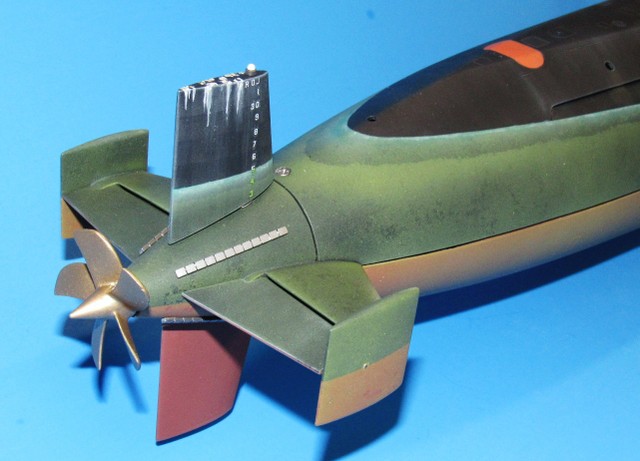
This step-by-step planning and execution regiment is personified in the tail-cone sub-assembly of this little 1/96 scale BLUEBACK r/c submarine model kit:
Where will cast resin, machined metal, cast metal, stock brass rod, and screw fasteners be best employed to achieve this component dense sub-assembly -- an assembly amicable to easy access or removal for later adjustment or replacement? How to engineer the linkages and running gear to work bind-free yet avoiding mechanical interference with other mechanisms sharing the tight confines of the tail-cones interior? And in what order are the manufacturing and assembly tasks most efficiently performed?
Chronology of tasks (the sequence of events) is a vital consideration: Fabrication and/or assembly of part-A to part-B is done and verified correct before addition of part-C. Proper planning, establishment of a rational methodology and chronology is key to streamlined and enjoyable model work.
**** Poor Planning Produces Problematic Products. Anything worth doing is HARD!
It's all about avoidance of putting the cart ahead of the horse, or making the cart from the wrong stuff.
You'll notice that I have not yet attached the tail-cone sub-assembly to the lower hull. That's because it's much easier to handle this small, complicated item off-hull till all the inner workings have been installed and tested -- only then will the tail-cone be joined to the hull. And that general rule holds for most other sub-assemblies.
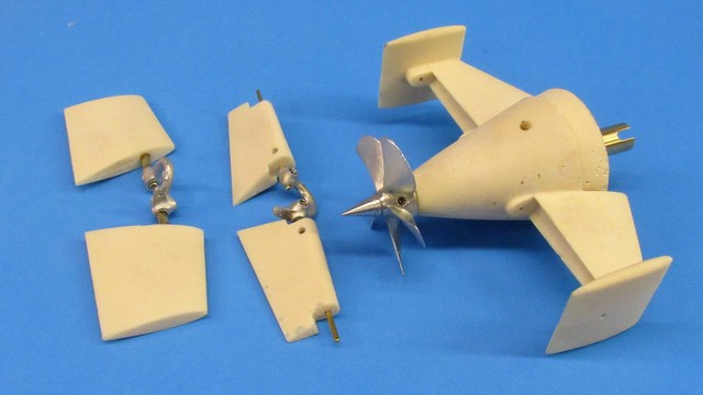
This is a kit. Every part needed should have already been at hand. But, no propeller... ****! The other elements of the running gear -- propeller shaft, universal coupler, thrust washers, Oilite bearings -- were installed, but the sub-assembly was not complete.
Fortunately I still had in the shop one of my metal casting tools for 1/96th scale BARBLE class propellers. So, I made one. With that done, the propeller in place, and everything working in concert, I could confidently proceed with attachment of the tail-cone to the lower hull.
I find white-metal to be an ideal medium when the situation calls for reasonable strength from low wall thickness structures. It is also a medium that is easily machined by boring, threading, and worked with common hand-tools. When pickled properly this metal alloy will bond well with adhesives, fillers, and primer.
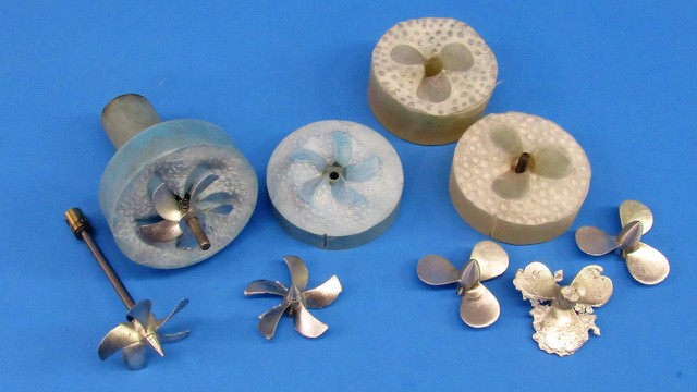
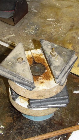
While I was set up for gravity pouring of molten metal I also worked up a few propellers for a 1/35th Type-23 model I'll be working on next year. You see the two rubber tools here. Note that the BLUBACK propeller tool has, as an element of the upper half of the tool, a long neck. This has running through it an extended sprue channel through which the molten metal is introduced. The height of the sprue, the 'pressure head', through gravity, produces a significant force at the bottom of the tool. That force insures a quick and complete fill of the propeller cavities when the liquid metal is introduced.
The Type-23 propeller tool needed a removable length of brass tube to produce the needed pressure head that insured a complete fill.
And you can see what happens when you screw things up!
You change the temperature of a substance enough you change its state. Liquid, solid, gas, or plasma. Metal casting is simply taking a metal that is a stable solid at room temperature, raising its temperature till it changes state to a liquid, then pouring that liquid into a mold (tool) and allowing it to freeze back to the solid state. Nothing to it.
Note the long neck of the upper tool half. The higher the sprue channel, the more pressure exerted at the bottom -- where the cavities that give form to the propeller blades and hub are -- insuring a quick, complete fill of the tool during the pour.
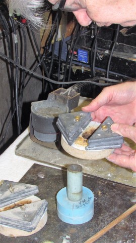
I've already installed a stainless steel pin (core) in the lower tool half that will produce the 3/16-inch diameter propeller shaft bore centered in the hub of the eventual propeller casting. Here I'm placing weighted discs atop the tool to squeeze the halves together tightly, this to minimize flash. Gravity is our friend: it holds the tool halves together and, because of the metals high density, produces the pressure needed to jam the molten metal into the tools cavities.
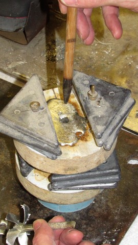
Once the molten metal is poured, and before it has time to change state, I jam a wooden dowel into the sprue hole. This prevents the solidified pile of excess metal atop the tool from linking with the column of metal in the sprue, which would present an entrapment situation. Guess what motivated me to employ this trick?!

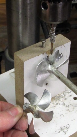
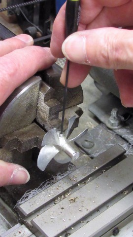
This drilling fixture is used to hold the propellers rotational axis perpendicular to the bit of the drill-press, no matter the angular displacement of the propellers hub to the bit. Once the hole is drilled it is tapped for a 4-40 set-screw (grub-screw for you European's) that secures the propeller to the propeller shaft. During this work the long sprue column is retained as it serves as a useful handle during the drilling and tapping operations. The excess sprue is sawed off once the set-screw is in place.
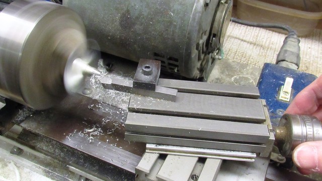
The last major machining operation on the cast metal screw is to spin it in the lathe as the 'dunce-cap' tapper is formed. Here I'm zeroing a length of shaft to the chuck with the aid of a dial-indicator.
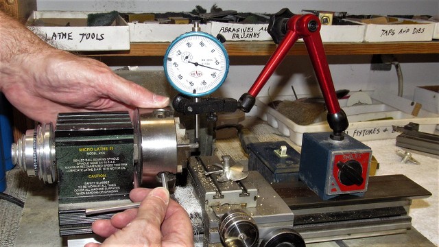
The propeller is secured to the chuck retained shaft and the work is brought up to speed.
A tapper tool-holder is mounted atop the cross-slide and used to produce the conical tapper of the propellers dunce-cap.
Dad taught me shop-safety. It went like this:
MACHINES DON'T CARE
MACHINES CUT METAL AND FLESH WITH EQUAL ENTHUSIASM
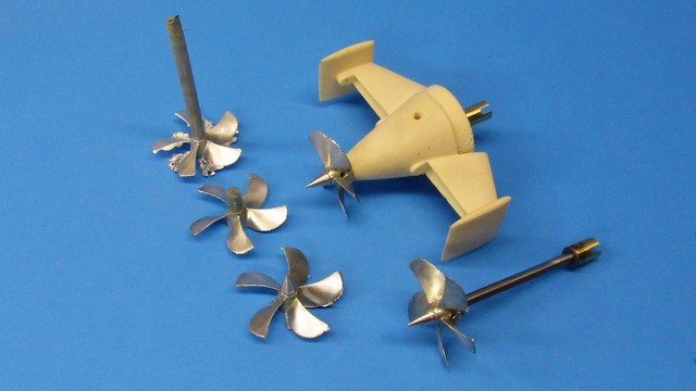
The three propellers to the left show the three major stages of cast propeller fabrication: Casting; trimming, which includes removal of flash and provision of the securing set-screw; and dunce-cap shaping.
The propeller shaft is prevented from lateral or axial motion but free to spin within two Oilite bearings. The bearing at the stern steadies the shaft laterally and absorbs ahead thrust load. The bearing at the front of the tail-cone steadies the shaft laterally (and along with the stern bearing assures that the shaft falls along the boats longitudinal center-line) and absorbs the astern thrust load.
 Who is John Galt?
Comment
-
Who is John Galt?Comment
-
Carry on, guys. I love seeing the master at work.Of the approximately 40,000 men who served on U-boats in WWII, it is estimated that around 28,000 to 30,000 lost their lives.Comment
-
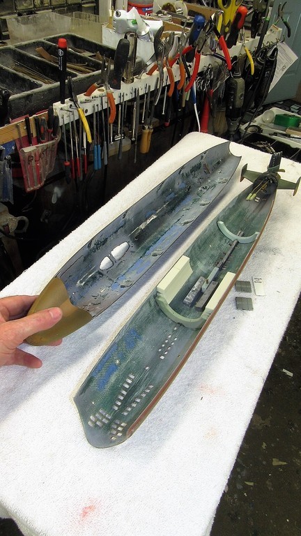
A single machine screw at the stern is the only thing holding the upper and lower hull halves together. This simple and quick means of attaching the hull halves is possible through utilization of the 'Z-cut'. Named because if you look at an assembled hull from the side you will note that the three breaks between the halves form a 'Z' pattern; the forward radial break, at the bow, runs from the keel up to the central longitudinal break that that runs aft nearly the entire length of the hull and transitions as a radial break traveling up from centerline to the top of the tail-cone. When assembling the two hull halves a recessed radial flange in the lower hulls forward end tucks up tight within the bow portion of the upper hull.
All it takes to assemble the hull is to engage the forward radial flange of the lower hull into the bow piece of the upper hull, then lower the after end of the upper hull down onto the stern cone radial flange and make up a single machine screw to hold that down tight. That's all there is to it.
A quick, fool-proof, and effective means of gaining access to the internals of the wet-hull type r/c model submarine. And who do we have to thank for this scheme that has been in vogue now for several decades? Dan Kachur and Greg Sharpe. To the best of my knowledge these are the guys who developed and popularized this method of internals access.
I modified the flange-forward bearing foundation piece by opening it up a bit. This done to facilitate a GRP reinforcement of the tail cone-to-hull union after tacking it in place on the lower hull with CA. Though this weakens the bearing foundation a bit axially, I determined that the backing loads presented to it in operation will be no where strong enough to distort or break the bearing foundation under extreme backing maneuvers. (best laid plans of mice and men...).
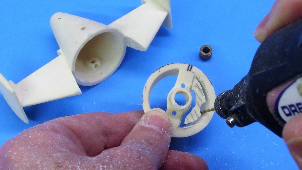
Cast polyurethane resin is easily milled away using a common drill bit spun at high speed. Only took minutes to perform this surgery.
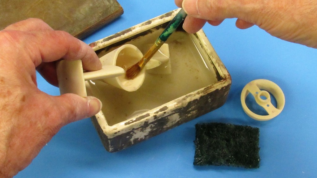
It's vital that every kit part, be the substrate polystyrene, polyurethane resin, epoxy-glass, metal or wood be prepared for adhesive operations by removing all oils, greases, fuzz, pitch and water from the model parts surface. In the case of polyurethane and GRP structures I'm dealing with here, a good scrubbing with lacquer thinner is the best way to go. The soaking is short-term (too long in the bath and the resin parts will go wonky on you) and accompanied by vigorous scrubbing with a stiff brush, steel-wool, a green-pad or other such conformal tool that will get into every crevasse and crease.
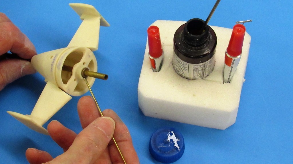
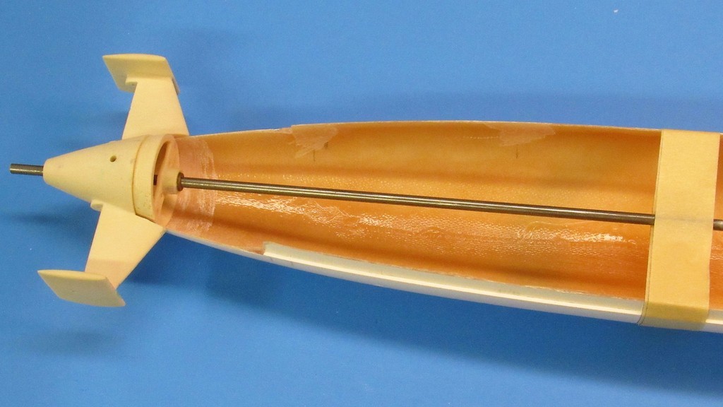
With the radial flange-forward bearing foundation permanently adhered to the tail-cone I installed the forward Oilite bearing and centered it with a short length of handy 3/16-inch diameter brass tube. I then applied thin formula CA to secure the bearing in place.
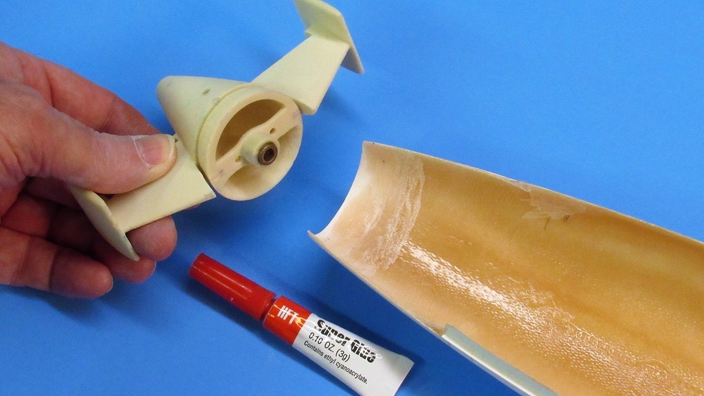
The after end of the lower hull -- where the flange of the tail-cone would seat -- was ground to a wall thickness equal to the radial flange recess depth of the stern-cone. Repeated test fittings (a tight friction fit assured by the leading edges of the horizontal stabilizers nesting up tight against the outside of the lower hull) and grinding away at the internal wall thickness of the stern finally got things to the point where the surface of the tail-cone matted flush with the lower hull.
Initial bonding of the tail-cone to the lower was with CA adhesive. But only to fix the assembly in place. The real strength element holding the assembles together would be fiberglass tape saturated with epoxy laminating resin.
Before tacking the tail-cone in place I ran a 3/16-inch rod through the bearings, carefully adjusting the tail cone position till the rod ran down the hulls longitudinal centerline. This insured that the propeller shaft thrust-line would be perfectly aligned with the centerline of the hull.
The CA was applied inside and out, wherever the resin tail-cone met the GRP lower hull. Using thin formula CA insured that capillary action would drive the adhesive into gaps I could not get at otherwise.
It was in this condition that the CA was applied and left to sit for a night as the adhesive found its way and cured rock hard.
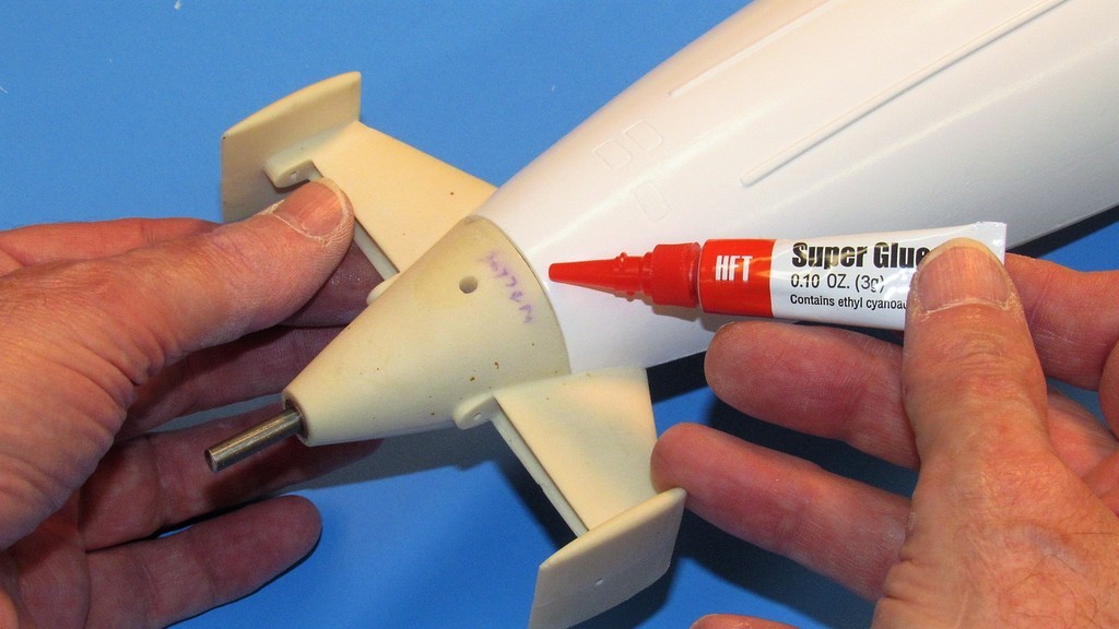
The trouble with most CA adhesives is that the cured bond fractures easily when subjected to a shear shock-load. And since most of us r/c submarine jockeys play hard and drive stupid-fast, collisions with pool sides, bottom, and each other are a fact of life. So, without a more resilient bonding medium, CA is not enough to hold the tail-cone in place.
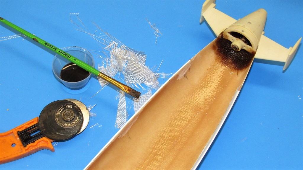
Here I'm overlaying fiberglass cloth, saturated with West System epoxy laminating resin over the union between GRP lower hull and resin tail-cone assembly.
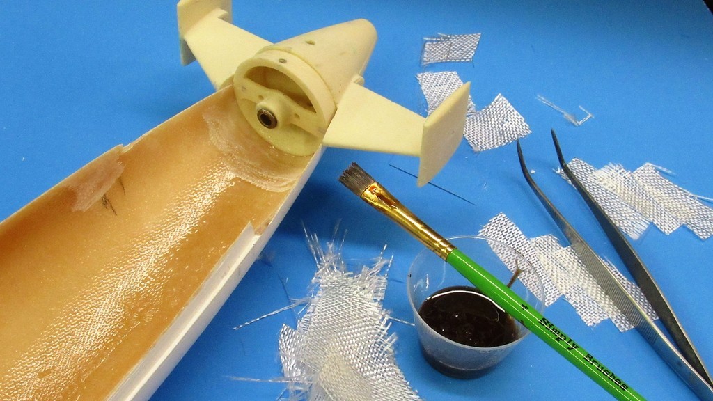
I laid three plys of fiberglass cloth to each side of the tail-cones lower rudder operating shaft hole. Each layer of glass long enough to extend about a half-inch forward and aft of the radial flange-forward bearing foundation piece.
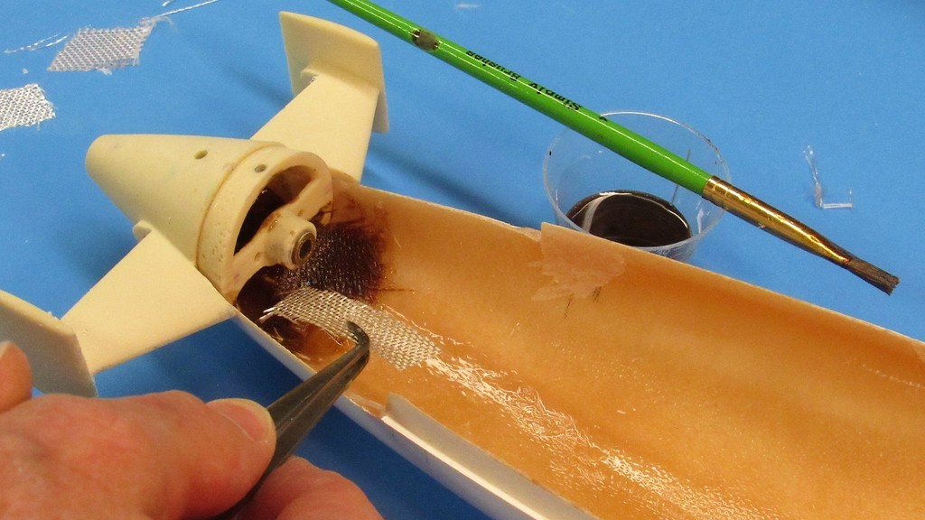
NOW! This is one tail-cone assembly that won't be knocked off without a fight the other guy will long remember!
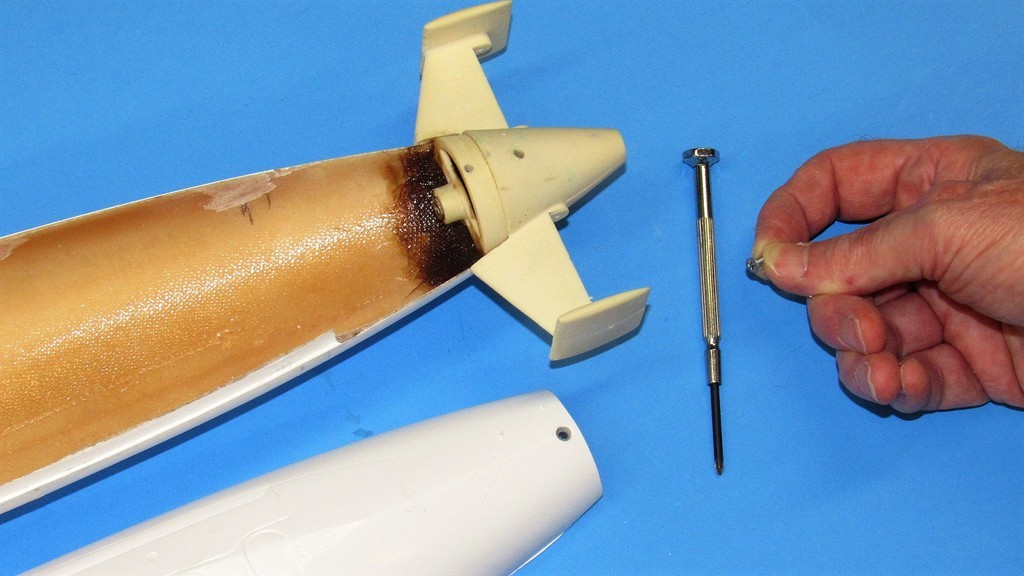
The single 4-40 flat-head machine screw that holds the upper hull down tight upon the lower hull. It's the recessed radial flange at the front end of the lower hull, engaging within the bottom bow piece of the upper hull, that holds the front-end in place.
The tapped hole in the resin flange of the tail-cone is not strong enough for field use. I'll install a metal insert drilled and tapped and glued within the radial flange eventually -- this will make the fastening strong enough not to strip out with usage.
Who is John Galt?Comment
-
How do you place the dive/rudder yokes inside? The top passage?Of the approximately 40,000 men who served on U-boats in WWII, it is estimated that around 28,000 to 30,000 lost their lives.Comment


Comment