

Wow David. I'm sitting in an airport for 2.5 hours and went through this whole thread in one sitting. Thanks so much for sharing your craft!
-
-
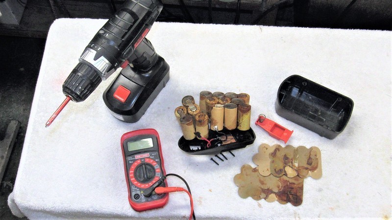
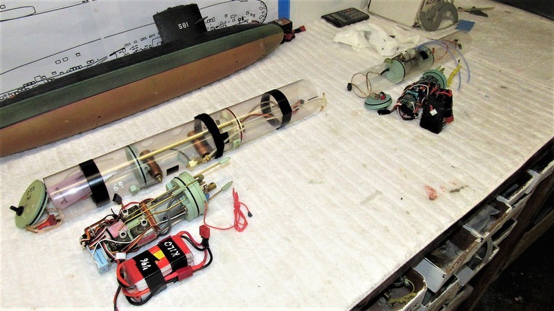
I assume most American's here have made good use of the wide and varied selection of hand and power tools offered by Harbor Freight. I sure have! Not high-quality stuff, but good enough for our work. However, sometimes the Chinese stuff will throw you a curve-ball. Such is the case with this 'new' 18-volt battery pack used with their recent line of battery operated hand-tools. Looks like it was immersed in salt water somewhere between the orient and here -- I suspect its shipping container, stowed above the main-deck, might have taken a wave or two during the Pacific crossing. When I got it, it would not take a charge. OK, enough Communist China bashing for the moment.
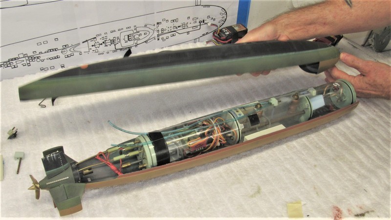
Removing the slightly squeezed upper hull half from the compression fixture, I was happy to see a significant restoration of the original circular cross section throughout the length of the hull half. As the lower hull had a longitudinally running flange, all I had to do was install an array of indexing lips within the lower hull to engage the inside surfaces of the lower hulls flange to pull the seams of the two halves into proper alignment.
Cast resin, carbon reinforced indexing lip blanks were cut into three's and prepared for mounting within the upper hull.
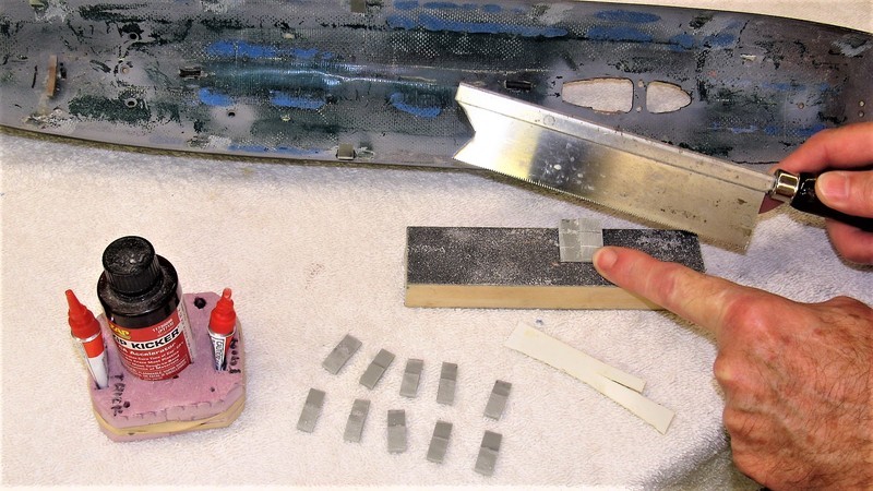
Before CA'ing the indexing lips I first ascertained the mean thickness of the lower hulls flange (.030") with a micrometer. I then made a 'indexing lip gauge' from a like thickness of styrene sheet. This gauge installed between the lip and the inside surface of the lower hull into which would later slide the lower hull flange during assembly.
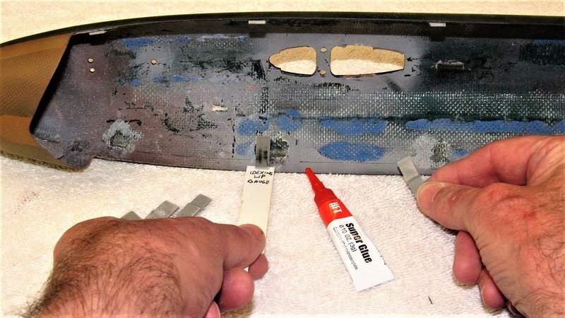
And the desired result: the two hull halves with their longitudinal edges butting up tight against one another in almost perfect alignment. We'll see how well this holds up after the assembled model has been left sitting under the summer sun come next sub-regatta!
 Who is John Galt?
Comment
-
The interior of a free-flooding r/c submarine is wet with the exception of the compartment(s) needed to keep the propulsion, control, and ballast sub-systems dry. Trimming the submarine involves matching the weight of water it displaces to the weight of the vehicle itself -- that's how you achieve 'neutral' buoyancy in a fluid. The foam installed in the wet portions of the hull are there to meet the displacement requirement.
It's vital that the displacing element be light of weight and will not, in time, saturate with water. That requirement is met by using a tight, closed-cell type foam. In this case, a professional model building medium, RenShape. This easy to carve and machine stuff is a light-weight foam, with a density of twenty-pounds-per-cubic-foot.
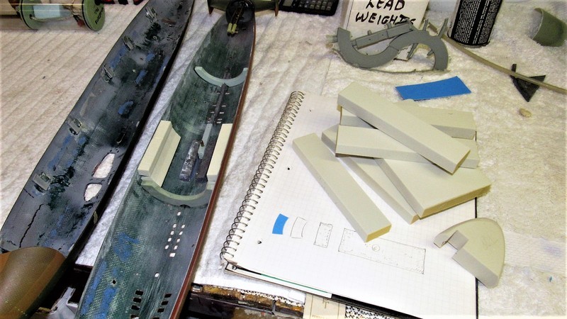
A shot of the end-game -- installation of closed cell floatation pieces tightly crammed within the annular space between SubDriver and hull -- to give you perspective of what went on to get these precisely shaped pieces of foam installed.
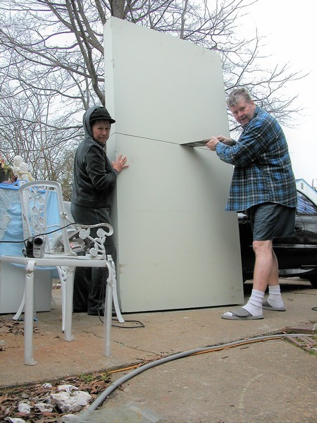
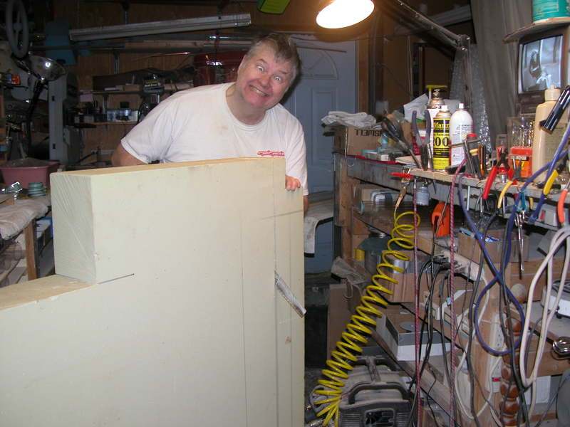
We received this big piece of RenShape in support of a MIT tow-vehicle job commissioned a while back. fortunately, for us, we only used a fraction of the material on that job and have since been using the remnants for master, jigs; and floatation piece, such as the work described here.
The initial cut, just to get this thing into the shop after an eighteen-wheeled truck dropped it off, with no ceremony, in our parkway. Ellie was not amused!
Hacking away to further reduce the RenShape to manageable sized pieces for later work. What a mess!
And this last shot, taken only a few days ago, of the raw cutting process as I got medieval on this hunk of low-density RenShape in support of the floatation work discussed here.

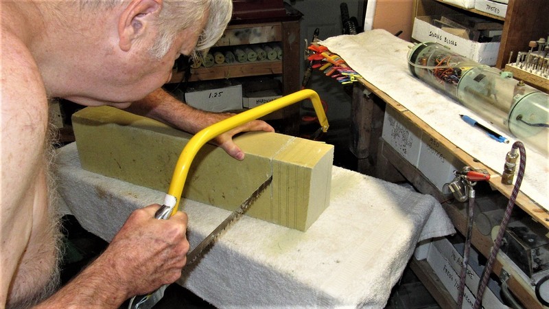
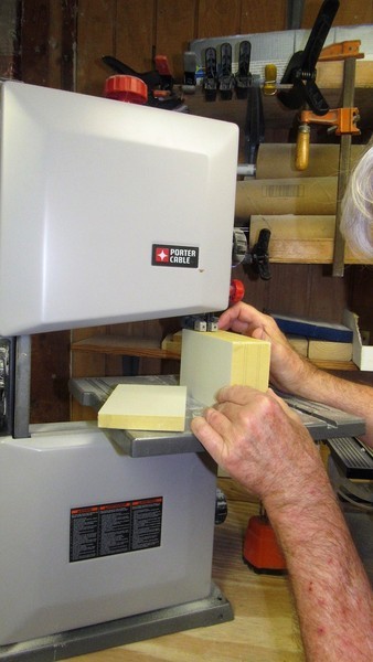
I used the bandsaw for the remainder of the blank work, then made use of the oscillating drum sander to render the concave face of the inboard pieces of floatation foam. The rest of the work was completed with razor saw and sanding blocks.
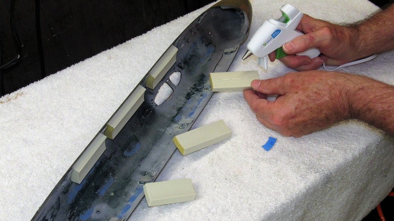
And, finally, the floatation pieces were installed within the hull with the aid of a hot-glue gun.
Who is John Galt?Comment
-
Make it simple, make strong, make it work!Comment
-
Comment
-
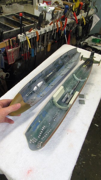
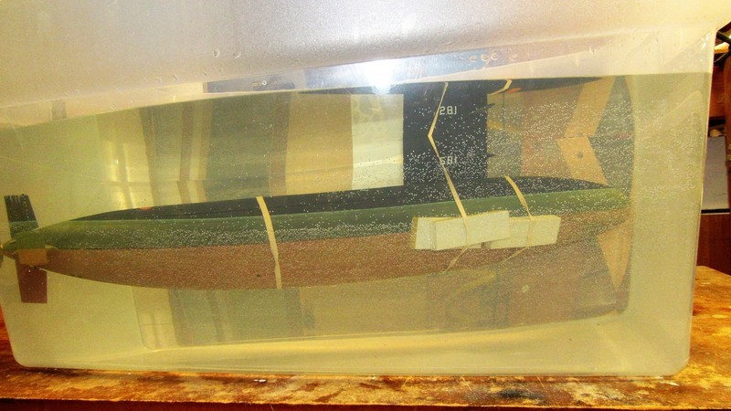
With an initial amount of buoyant foam secured within the lower hull it came time to dunk the model in the water – ballast tank full – to find out how much foam had to be installed to achieve neutral buoyancy (or, in some rare cases, the removal of excess foam).
In this case the BLUEBACK model sank like a rock. I easily determined the amount and location of additional buoyant foam needed by simply rubber-banding hunks of the stuff to the outside of the model.
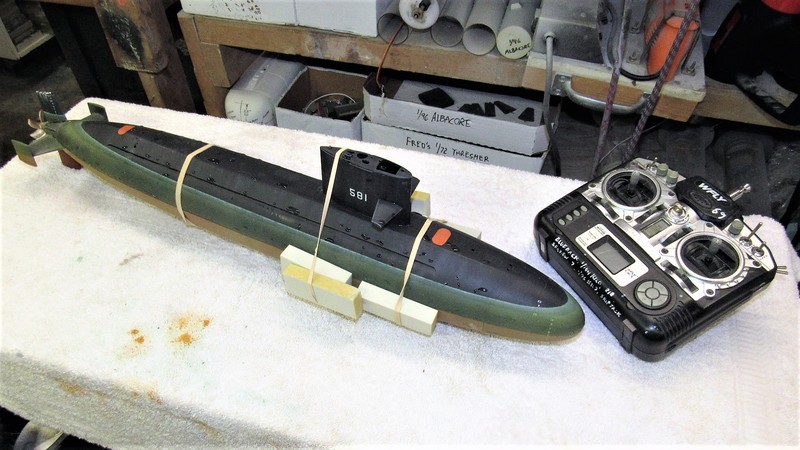
And this is the objective: the nearly completely submerged model (only a small portion of the upper sail projecting into the air) resting at a zero bubble angle. To achieve this I kept adding blocks of foam and moving them fore or aft as required. In this condition the submarine is said to be at proper submerged trim.
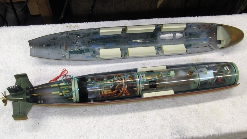
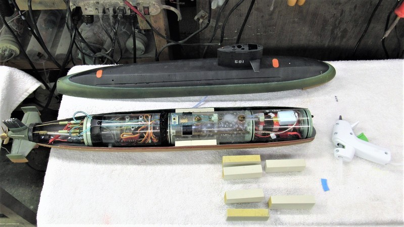
Now, to shift all that foam from the outside to the inside of the model – not an easy task, as the annular space between the BLUEBACK hull and SubDriver is only a half-inch or so, and tightens even further near the bow and stern tappers.
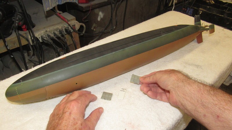
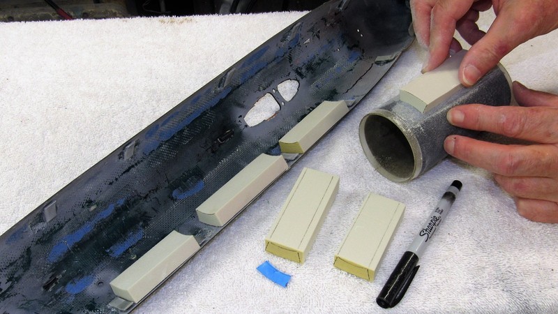
To maximize roll stability you want the foam as high as possible, but not higher than the submarines designed waterline. So, most of the foam you see here had to go within the upper hull half. The work went pretty much like how I installed the buoyant foam into the lower hull.
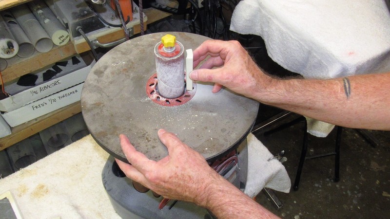
Using the cylindrical sanding 'block' I trued up inboard faces of the installed buoyant foam pieces – this to afford clearance of the SubDriver. Counter to my previous comment, I did install some of the foam above the models designed waterline. You do what ya gotta do!
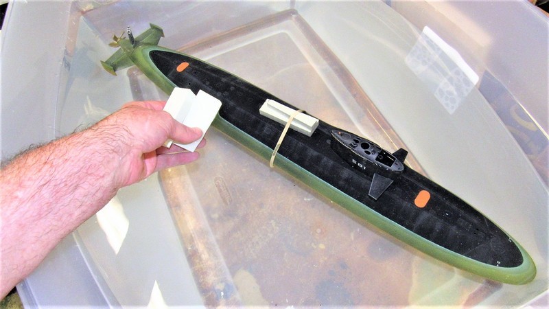
With that the model was again assembled, but this time I turned on the transmitter and receiver so I could vent and blow the ballast tank while it was in the test tank. The models ballast tank was vented. I found that the model was still a tad negatively buoyant, but this was negated with a little more buoyant foam. As you see here those touch-up pieces of foam were rubber-banded atop the hull. Note that the models submerged trim has just the top of the sail projecting into the air. Perfect!
I then blew the tank dry and observed where the actual waterline was in relation to the designed waterline. Any disparity is fixed by moving foam above/below the designed waterline as required – the net buoyancy remains the same, but the buoyancy in surfaced trim has been altered to make the model float at the designed waterline with the ballast tank empty.
And that, boy's and girl's, is how you trim a free-flooding r/c model submarine for surfaced and submerged trim. Note that the discussion now departs from the BLUEBACK and shifts to the same process applied to my little 1/96 Type-212.
Also, I conclude this screed with a rant describing what it takes to be successful at this game. Buckle up!
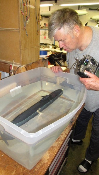
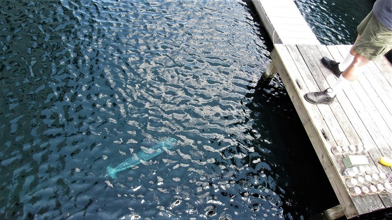
Slobbering old fool checking the submerged trim of his Type-212 before boxing it up and taking it to Nauticus for our monthly run. Just one of the many pre-mission checks done before even thinking about loading the car for a days fun.
Successful r/c model submarining demands more attention to detail, maintenance, trouble-shooting, and dogged determination than any other form of r/c vehicle operation. These very wet vehicles are not crummy little foamies you just charge up, pull out the antenna and point skyward. NO! R/c submarining is a high-maintenance, intolerant, unforgiving, demanding *****! You play by the rules or you go home with an empty boat stand!
I've broken this game down into three phases: Pre-Mission checks and operations; Mission checks; and Post-Mission checks and operations. (you navy Diver's might see a pattern here).
Before I even load up the car for an afternoons play-time I've already put several hours of pre-mission checks and operations in. Then, once at the lake/pool/river I conduct mission checks to insure everything works before I head out to deep water. And the fun never ends: when I get home after a hot, tiring day, I still have a few hours of post-mission checks and procedures to perform, insuring everything is put into a preservation mode and problems corrected.
I see so many of you guys at regattas with your boat never leaving the table. Why? I'll tell you why: because you got cheap with your time and resources, that's why! You treat this facet of the hobby like your r/c submarine is just another cheap-ass RTR Chinese play-toy! How come I'm that guy still operating in the water come 2PM -- usually the only one left standing. How's that? Because my **** works... and yours don't!
Hint: If your maintenance-to-running ratio is less than 2, you're not putting enough effort into this game.
There!... done. That pop sound you just heard was me extracting my foot from your ass.
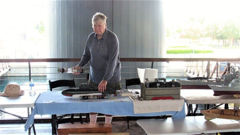
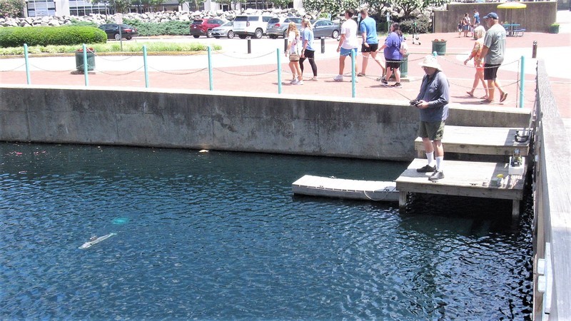
At Nauticus with my fellow Elite Fleet partners in crime. In the middle of some mission checks before getting the model wet again. You can see the fresh water pond in the background – the perfect place to run our models. We've been doing this for about ten years and is a monthly event in the summer months.
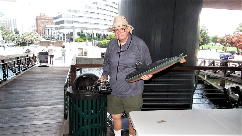
The Nauticus people even built this fine little step-off pier for our use. Note the use of a PVC pipe 'boat caddie'.
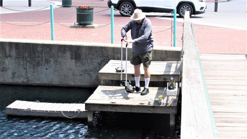
The first mission check at the site is to dive the boat close-in – so you can jump in if you have too – and affirm that the boat will assume proper submerged trim with just the top of the sail sticking out of the water and resting on an even keel.
The ballast tank is then blown dry and proper surface trim is verified. Only then do you take the boat out into deeper water, confident that things are working as they should.
Arriving home, the car is unpacked and all I want is a drink of cold water, a warm shower, and a long nap.
But... Nooooo! Post-Missions got to get done.
NEVER store a WTC/SubDriver/Module/whatever all buttoned up after an outing. Never!
First thing is to break out the note-pad you kept at the site and used to jot down problems encountered during mission-checks and operation of the boat on and out of the water. Post-mission is the time to address those issue.
The fun never ends!
Who is John Galt?Comment
-
Thanks Dave for the lesson on how to apply the foam pieces. I learned a new trick with the rubber bands. Comes in handy as my new fish is soon heading for the tank.Comment
-
Primarily this post deals with the start of the final push to complete the 1/96 STURGEON kit master and tooling so the Nautilus Drydocks can get this product into production and into the hands of a patiently waiting clientele.
But, first, a little house cleaning as I conclude the discussion on how I installed the last of the flotation foam into the 1/96 BLUEBACK model.
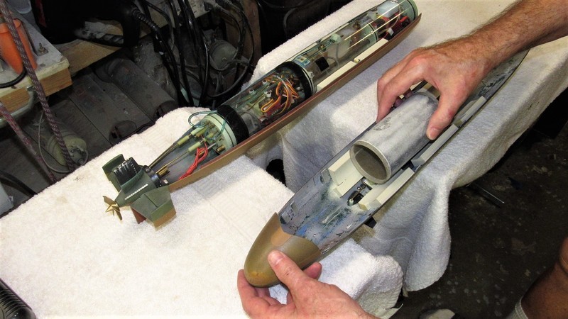
After going through all that careful work of contouring the pieces of flotation foam that were glued within the upper hull I was disappointing to find that I could not enclose the models upper and lower hull with the SubDriver in place. Yet, removing the SD, the hull halves fit together perfectly! Obviously the SD was making contact with the just installed foam. Damn!
Normally I would slather black Artist oil paint over the top of the SD, slam the upper half of the hull in place as far as it would go, remove it, and examine where the black (very messy) paint made contact with the offending areas of flotation foam or other structure making contact with the SD.

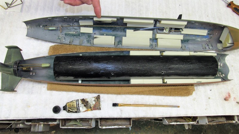
The only variance of the procedure was to dragoon a discarded length of 2.5” diameter cylinder in as a proxy for the models SD – I hate cleaning up oil paint! So, after installing the proxy and brushing on the black oil paint I pressed the upper hull into place as far as it would go, I pulled it off and, presto-chango. There were the smears of black Artist oil, precisely directing my wrath towards the offending hunks of foam and... surprise!... also the flexible hose that runs from the sail mounted induction snorkel down to the induction side of the SD's SAS ballast sub-system.
Pictured, an accusatory finger points to the paint smears on two of the after pieces of recently installed flotation foam. The right of that you can make out black paint on the end of the snorkel flexible hose. Ah, Ha... Gotcha!
A bit of sanding of the foam took care of the interference fit between foam and SD. And a re-routing of the snorkel induction hose solved the contact problem between it and the top of the SD. The proxy cylinder was then unceremoniously slam-dunked into the dumpster, the operational SD installed and – to my great joy and relief – the two hull halves sat down on each other in reasonable alignment and with their longitudinal edges actually making contact. Success!
Damn... I'm good!
OK, back to the 1/96 STURGEON masters and tooling – work long delayed by current events.
Time is at hand to produce the rubber tools needed to produce production cast resin sails. First task is to construct a flask, or containment, that will hold the liquid tool-making rubber as it changes state from liquid to solid. A simple box constructed from 3/4” thick shelving (particle board faced with a veneer of white plastic). My go-to material for flask making. In background is the tool I made for producing cast resin stern-cones for this kit, in shot to give you an idea of what the sail flask will look like eventually. But, at this point I'm in the lay-out process where a paper study validates rubber wall thickness which in turn drives flask geometry.
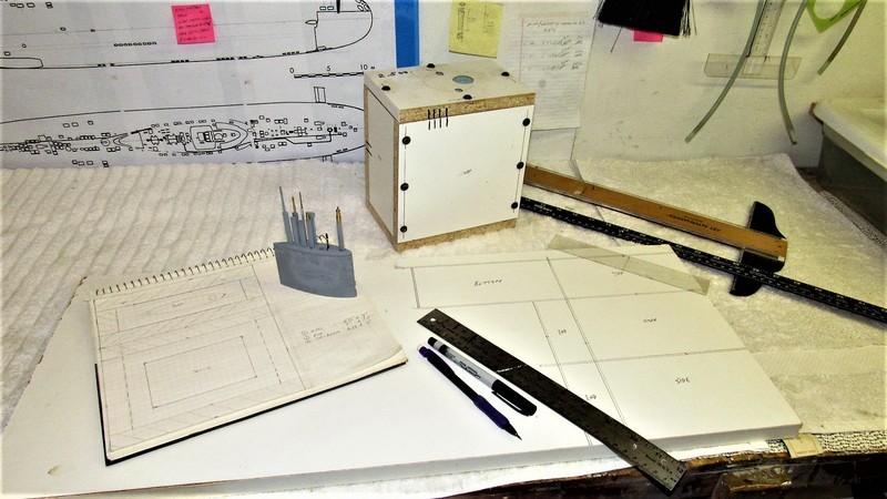
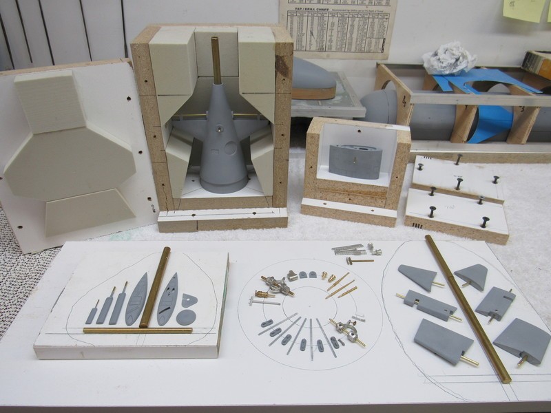
About two years ago I completed the masters and tooling for a 1/96 THRESHER kit for another customer. I show off some of the tooling work here to illustrate how the STURGEON's sail master will be positioned within its flask during the rubber making process. It's a bit involved as the master – and subsequent resin pieces – is hollow. Typically, for a tool like this, it takes about three discrete pours of rubber to properly encapsulate the master yet will permit separation of the tool elements during master (and later production part) extraction. This is why the flask faces can be unscrewed and pulled away from the hard rubber tool.
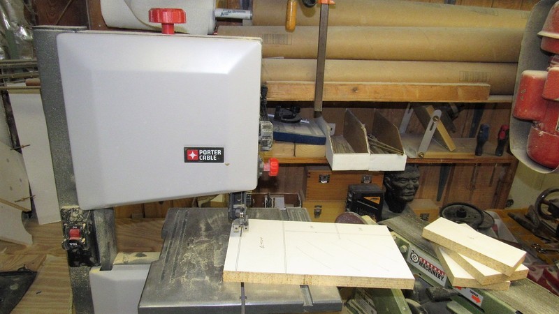
From the orthographic drawings I loft the dimensions onto the shelving stock and go to town with band saw and drill-press. I'm making a box here, no big deal.
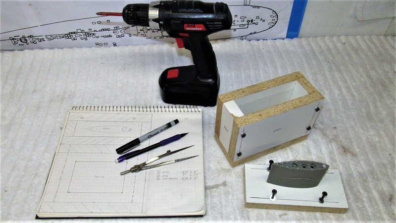
And here we are. Flask. Awaiting final detailing of the sail master.
Who is John Galt?Comment
-
Very cool work David! I for one am interested in the Sturgeon as you previously referred to it as tge “best running boat”Last edited by biggsgolf; 07-24-2021, 09:22 AM.Comment
-
You could use carbon paper instead of oil paint.Make it simple, make strong, make it work!Comment


Comment