today's work

Collapse
X
 
  • Time
  • Show
Clear All
new posts
  • He Who Shall Not Be Named
    Moderator
    • Aug 2008
    • 12253

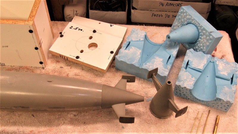
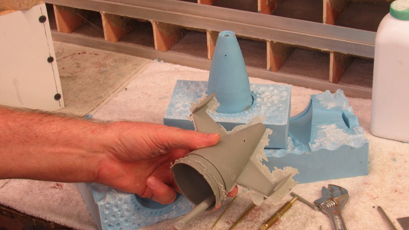
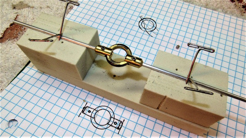
    After about twelve-hours under two heat-lamps the block of Silicon Room Temperature Vulcanizing (RTV) rubber had cured hard and I took the flask apart.


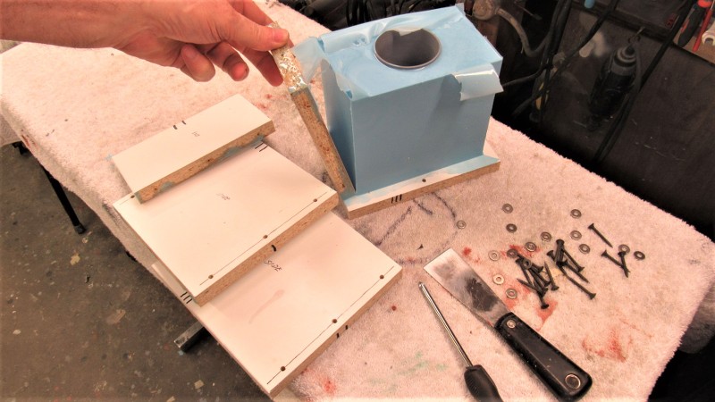
    I yanked out the brass rods and established centerline verticals on the rubber block to help guide me as I cut the block into two approximately equal halves -- that operation, inevitably sloppy, would produce the keying network that would register the two halves together. More on that horror show shortly.


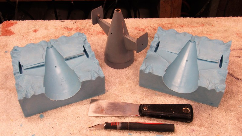
    I purposefully avoided straight cuts at the surface of the block of rubber -- the wavy lines would insure an aggressive keying network. But, about a half-inch into the cut I straightened the flange as best I could and worked as carefully as I could to avoid cutting into the master, though some dings (easily filled and sanded smooth later) did occur.


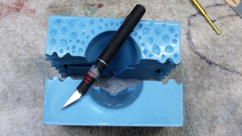
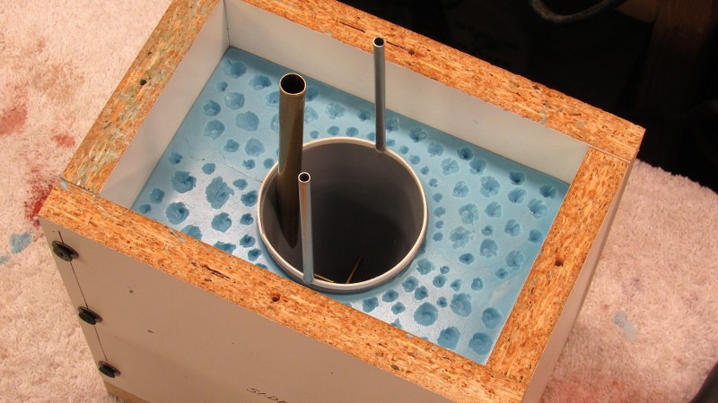
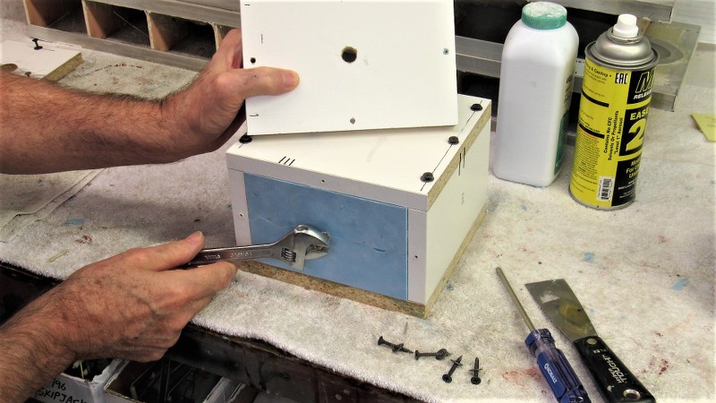
    Into the top of the block, that world become the flange line of the core piece of the tool, I dug out deep 'dimples' to start the keying network between the core portion of the tool and the two-piece block of rubber beneath.


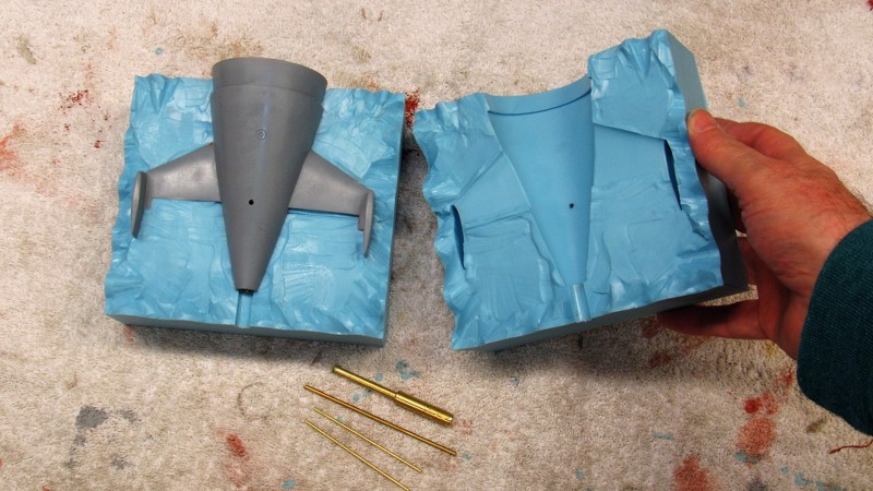
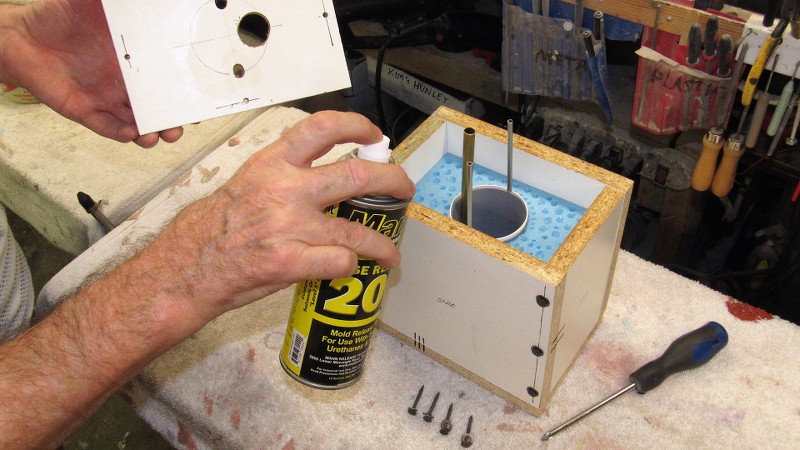
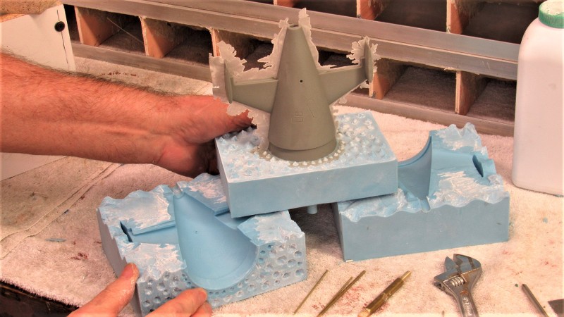
    The tail-cone master was reinstalled into the two piece 'block' and a riser ring attached to the forward end of its radial flange -- a form of bubble-catcher. Atop the riser are two tubes that will form the vents within the core portion of the too.


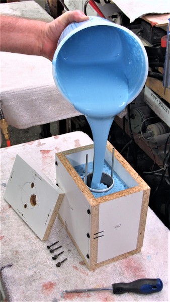
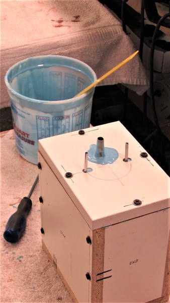
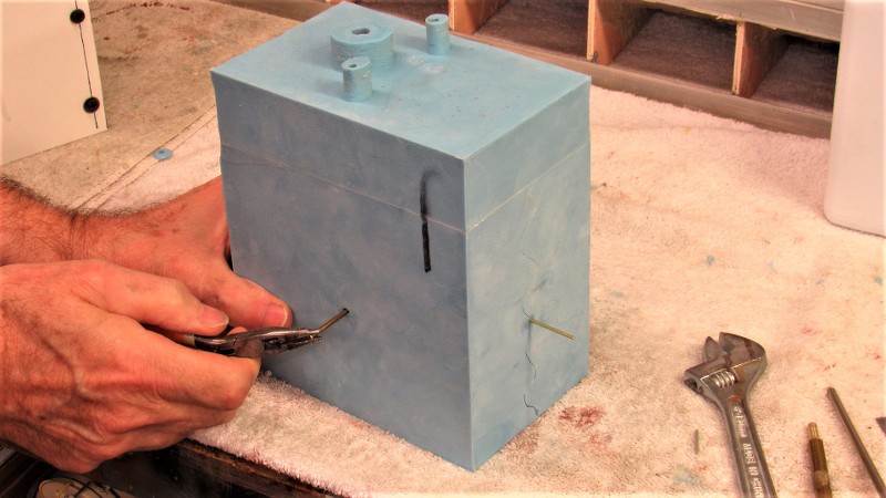
    Pouring the third section of the tool. The large brass pipe will form the sprue.


    Who is John Galt?

    Comment

    • Monahan Steam Models
      Captain
      • Apr 2020
      • 755

      Okay it’s been a couple days. Where’s our update on your creation? You’re holding out on us, I know it!

      Comment

      • He Who Shall Not Be Named
        Moderator
        • Aug 2008
        • 12253

        And FINALLY! I transition from tool making to part making. Here is the typical set-up for the casting of a polyurethane resin part. The resin, mixing container, scale to measure the liquid resin, the assembled tool, the hand-tools used to install/remove the core pins, and the talc and part-release silicon spray used to protect the rubber from chemical attack from the resin as it changes state from liquid to solid.

        ​​​

        Introducing catalyzed resin into the tools cavity through the large diameter sprue hole. Before the resin begins its state change the entire tool is subjected to pressure to crush any small bubbles of gas entrapped within the tools cavity -- this to insure a pock-mark free casting. The pressure pot is of the kind used in pressure spray-gun equipment, an item available at any local Harbor Freight.

        ​​​

        The Alumilite resin I use can be demolded within twenty-minutes after the pour, but I typically let things set for a good hour before un-pressurizing the pot, removing the tool, and stripping out the cast resin part.

        ​​

        Removal of the rubber elements of the tool from the flask starts with twisting the base-pin from the bottom -- this pin serves as a core element that forms the 5/16" bore at the stern of the tail-cone casting that later accepts the Oilite propeller shaft bearings. I milled two flats to the lower end of the pin to permit easy twisting with a wrench, breaking it free from the hardened resin. It was then an easy task to pull the pin clear.

        ​​​

        Removing the brass rods that gave for to the holes in the sides and outboard tips of the horizontal stabilizers of the tail-cone piece. Those holes later passing the operating shafts of the stern planes and rudders.

        ​​​

        Seen to good advantage here the zig-zag keying between the two halves of the 'block' that comprises the majority of the tail-cone rubber tool.

        ​​​

        The four pins removed from the block, the two halves are pulled apart revealing the cast resin tail-cone part still attached to the core portion of the rubber tool that produces the parts hollow, thin-walled, interior. A little flexing of the rubber and part and it pops clear of the core. Only clean-up of the part is to shave off some flash, snap off the ring shaped riser, and grind the sprue away from the parts interior.

        ​​​

        ​​​

        Test fitting the tail-cone part to the GRP hull. Note how the radial flange will be glued to the lower hull, leaving the upper portion of radial flange to serve as the foundation upon which the after end of the upper hull will sit and be secured to with a single machine screw. Easy, quick access to the hulls interior -- the marvel of the Z-cut; an invention promoted many years ago by the two Canadian's, Greg Sharpe and Dan Kachur.

        ​​​

        ​​​

        ​​​
        Last edited by He Who Shall Not Be Named; 02-07-2021, 11:17 PM.
        Who is John Galt?

        Comment

        • He Who Shall Not Be Named
          Moderator
          • Aug 2008
          • 12253

          Originally posted by Monahan Steam Models
          Okay it’s been a couple days. Where’s our update on your creation? You’re holding out on us, I know it!
          Thanks for the wake-up-slap-across-the-chops. Indeed, I had posted here a few days ago but forgot to press the 'post reply' button. Dumb-ass move. Just posted it.
          Who is John Galt?

          Comment

          • Monahan Steam Models
            Captain
            • Apr 2020
            • 755

            Yup he was holding out!... And what does he come back with. Perfection right there people!!! Wipes the drool from the face over viewing such a perfectly executed masterpiece... Damnit, you’re good. Stop making the rest of us look like knuckle dragging amateurs.... Actually keep it up, we need to learn and evolve. Thank you!

            Comment

            • He Who Shall Not Be Named
              Moderator
              • Aug 2008
              • 12253

              Originally posted by Monahan Steam Models
              Yup he was holding out!... And what does he come back with. Perfection right there people!!! Wipes the drool from the face over viewing such a perfectly executed masterpiece... Damnit, you’re good. Stop making the rest of us look like knuckle dragging amateurs.... Actually keep it up, we need to learn and evolve. Thank you!
              Oh, stop!

              You're the genius gear-head this place has been missing since Skip Asay left the scene.

              And without getting my tongue too far up your ass, I must say that your metal crafting skills, engineering prowess, and machine-shop accomplishments have enlightened us all. Keep doing what you're doing here and any other forum you can find to spread the gospel. You're giving back much more than you're taking. Keep the ball in play!

              David
              Who is John Galt?

              Comment

              • Monahan Steam Models
                Captain
                • Apr 2020
                • 755

                Originally posted by He Who Shall Not Be Named

                Oh, stop!

                You're the genius gear-head this place has been missing since Skip Asay left the scene.

                And without getting my tongue too far up your ass, I must say that your metal crafting skills, engineering prowess, and machine-shop accomplishments have enlightened us all. Keep doing what you're doing here and any other forum you can find to spread the gospel. You're giving back much more than you're taking. Keep the ball in play!

                David

                Nope, won’t stop. Your talent of producing fine works, as a result of your hard won experience and practiced honed skills will not be just quietly admired. Sorry, the deafening silence to many posts is the jaw dropping mouth breathers opening the hanger doors helplessly out of shear Speechlessness. The few that comment are either aware of the skill it takes to see such creations at this level to the end or have tried and failed but can respect what you present.

                Keep the beautifully executed operations flowing Sir.


                Comment

                • trout
                  Admiral
                  • Jul 2011
                  • 3545

                  Yeah, what he said!
                  If you can cut, drill, saw, hit things and swear a lot, you're well on the way to building a working model sub.

                  Comment

                  • He Who Shall Not Be Named
                    Moderator
                    • Aug 2008
                    • 12253


                    As someone once pointed out here, model submarines -- sleek, featureless post-war types anyway -- are, when compared with surface craft, rather boring simple cylinders with little structure variance or detail to please the eye. For that reason alone I do everything I can to make the most of what eye-catching elements there are to liven up the presentation. For modern submarines the eye-candy is almost always at the stern or what projects from atop the sail.

                    Nothing brings a sense of purpose or catches the eye better than the many retractable antennas and optical devices atop the submarines sail. These two illustrations of a Small World Model 1/96 BLUEBACK, with and without masts, makes my point.

                    Sure, the model submarines sail can be jazzed up with oil-canning paint effects; dry-brushing to highlight edges and high-relief areas; and one can even provide practical dead-lights. But a big opportunity is lost if you don't also equip the display with extended fairings and scope cylinders.


                    That same model submarine sail with the removable mast farings added -- and the antennas and optical devices atop them -- now becomes something worth looking at. Also, on a practical r/c submarine running near the surface, the feather produced by the masts is a vital visual aid needed by the driver to help him know just exactly where the submerged model is!


                    Getting back to the 1/96 STURGEON kit. The sail masters: two sail planes; the sail proper; and two alternate sail tops. One sail top with scribed outlines representing the flush fitting tops of the mast fairings, and the other sail top provided with tear-drop shaped holes that would pass mast farings represented in the 'raised' position.


                    I give the eventual kit-assembler a choice: either represent the model with retracted masts, or raised masts. Here I'm giving final shape with a hand-vice to fairing blanks. Using a sanding block to get them to proper cross-section and thickness


                    Exacting model-building often required close-in hand-work -- the work firmly held in some kind of hand-vice at eye-level as you work it with the other hand. A jeweler's hand-vice takes many forms, the plastic wedge type above; beneath that a more traditional screw clamping type; and below the more familiar collet types used to hold the cylindrical shank ends of work so equipped.


                    I make these simple clamp type hand-vices for fragile work that would otherwise bend and break if not supported longitudinally -- such as these highly detailed rows of zincs being carefully engraved and sanded with the aid of this gripping tool. Note that the faces of the two clamp halves have glued to them sandpaper. It's there to assure a no-slip grip to the work. This hand-vice works through the pressure applied with finger and thumb, giving absolute control over clamping pressure.


                    Paralleling the work of making the masters and tools for eventual 1/96 STURGEON kit production is the assembly of a working model. Not only for my personal enjoyment, but primarily serving as a validation article to insure that all kit fit and function problems are identified and solved before committing the masters to tool making. I don't want to unleash a flawed kit on an unsuspecting public -- that would be bad ju-ju!

                    Three things I get straight before construction begins is to place the center of gravity (center of mass) at the longitudinal center of the hull; position the SubDriver (SD) so the center of the ballast tank is where the assembled models c.g. will be; and place the c.g. as low in the hull as possible to insure adequate static roll stability.


                    Modern single-shaft submarines usually present the problem of clearing the inter-connected stern plane and rudder operating shafts from the centrally located propeller shaft. Achieving the goal of interconnecting opposed control surfaces is done with a 'yoke' that provides a pass-through to the propeller shaft by providing a ridged structure. One yoke for the rudders, and one yoke for stern planes. This arrangement typified by these shots of the yokes and associated linkages I built for this 1/72 SKIPJACK class submarine kit.


                    However, at variance to this illustration, the 1/96 STURGEON's stern plane operating shafts will each have their own bell-crank as there is no clearance space between the nexus point of rudders and stern plane operating shafts. Other than that, this photo pretty much represents how the STURGEON tail feathers will be wiggled.


                    The two standard bell-cranks that would make up to the inboard end of the stern plane operating shafts were constructed from 3/32" bore Du-Bro wheel-collars that had soldered to them sheet-brass arms.

                    The rudder yoke on the other hand was constructed from a central brass toroid soldered to two bored out lengths of 3/16" brass rod. The trick was to devise a jig to hold the three brass pieces together as I applied solder to join them together.

                    That cast metal object to the left with the brass rod projecting from each end is a magnetic bell-crank used to rotate the sail-plane operating shafts -- it will be pressed into service (originally a part from our 1/96 THREASHER kit) when it comes time to make the 1/96 STURGEON production tooling.


                    Brass is easy to bend once you anneal the **** out of it. Just take the work to a red heat and let it cool to ambient temperature without quenching. The soft metal handles like putty, but quickly work-hardens, so you have to repeat the annealing till the work is bent and beaten to the shape desire.


                    A jig was slapped together from 20 lbs.-per-cubic-foot RenShape. As you can see, the toroid is sandwiched between the two rudder foundations. The jig insures that the shaft bores share the same centerline.


                    Plenty of free space around the suspended work so nothing catches fire. You don't want any of the jig to off-gas to contaminate the solder-metal union or to act as a heat-sink that would prevent quick, even wetting of the solder to the work. Hence the suspension of the parts in open air.


                    Two 3/32" diameter brass rods fit the bores of the two rudder shaft foundations. Lead-Tin Solder won't stick to aluminum.


                    I've made all sorts of part holding tools over the years, I made use of one with a 3/32" spindle as a holding tool as I hand-worked the rudder yoke master. Just slide the master onto the spindle, tighten down on the two set-screws and get to work with files, grinders, burrs, sandpaper, and wire-wheel. Much easier to hold the work this way than to grow calluses on the tips of your fingers!


                    Before adding the bell-crank element to the rudder yoke I first test fit the yoke within the tail-cone master to insure there would be no interference between the port stern plane bell-crank and the proposed location of the rudder yokes bell-crank. Check twice, cut once! Once the position was affirmed to work in the tight confines of the tail cone the bell-crank was added.


                    Who is John Galt?

                    Comment

                    • redboat219
                      Admiral
                      • Dec 2008
                      • 2735

                      Wish somebody would make a pdf file of this so I could print it out. I prefer hard copies over virtual.
                      Make it simple, make strong, make it work!

                      Comment

                      • rwtdiver
                        Vice Admiral
                        • Feb 2019
                        • 1768

                        Originally posted by redboat219
                        Wish somebody would make a pdf file of this so I could print it out. I prefer hard copies over virtual.
                        Romel,

                        I found that using your PC or Pads, and exporting into files of all the great photos and descriptions on submarine building that David and others share with us on this blog, really works well for me! Each file has a specific name so you can just pull it up anytime that you need that information. I keep all my files in my Pad. That way when I need information on a certain subject matter I do not have to go through the whole forum or individual blogs to try find the information I need. Much cleaner and more organized for me!

                        Rob
                        "Firemen can stand the heat"

                        Comment

                        • Ken_NJ
                          Captain
                          • Sep 2014
                          • 744

                          David, maybe I missed how you made the toroid. Once annealed, how did you get it to be a perfect circle?

                          Comment

                          • He Who Shall Not Be Named
                            Moderator
                            • Aug 2008
                            • 12253

                            Originally posted by Ken_NJ
                            David, maybe I missed how you made the toroid. Once annealed, how did you get it to be a perfect circle?
                            First I determined the maximum inside (to clear the propeller shaft) and outside (to clear the near-by stern plane bell-cranks) diameters of the toroid then reduced those measurements to a simple orthographic drawing on graph-paper -- two concentric circles. Duh!

                            I then annealed a length of brass rod (who's diameter would give me those diameters I mentioned), and bent it to shape with a pair of jewelers rounding-pliers. I lifted most of the primo jeweler's tools from Mom's work-shop during her wake.

                            6-in-1 Bail-Making Six Step Pliers Loop Making Round Jewelry | Etsy

                            I bent, annealed, bent, annealed, cursed, annealed, bent, threw things, annealed, and finally bent the damned thing till it matched the drawing.

                            I achieved a near perfect circle because I'm so damned good at this ****!

                            David
                            Who is John Galt?

                            Comment

                            • trout
                              Admiral
                              • Jul 2011
                              • 3545

                              If I may add another way I used to make links (for chain, bezels, and such) is a dowel or rod of wood or steel and wrap your annealed brass around it several times. Then use a jewelers saw to cut down the length of your brass coil, now you will have a loop that with some pliers, be able to make the cut surfaces meet and solder for a completed circle. I wish I had photos to share. So, I hope this makes sense.
                              Last edited by trout; 02-16-2021, 06:24 PM.
                              If you can cut, drill, saw, hit things and swear a lot, you're well on the way to building a working model sub.

                              Comment

                              • Scott T
                                Commander
                                • May 2009
                                • 378

                                Ye Olde Chain Maille Rings: There are many websites that will show you how to manufacture chain maille items, focusing on the different styles of 'weave' (how to combine metal rings together to make a protective and attractive garment) that you can use. Unfortunately, most of …


                                Click image for larger version  Name:	F2PHWUIFGMQDV8X.jpg?auto=webp&frame=1&fit=bounds&md=8c1c1417a19d4f20b12907a8edbc7658.jpg Views:	0 Size:	62.2 KB ID:	147574

                                Comment

                                Working...