
Once the edges of the two GRP hull halves had been worked smooth, and the sterns -- where a tail-cone part would eventually reside -- had been chopped off and trued to the radial outline, It came time to dissolve off the protective PVA part-release the two GRP hull halves picked up during the lay-up process. This done with the most powerful solvent on this planet: fresh water!
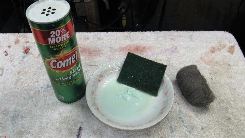
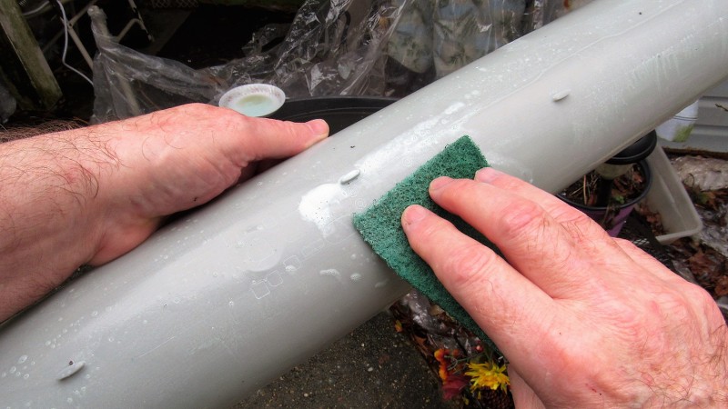
Killing two birds with one stone I mixed up a slurry of water and abrasive laden 'cleanser' powder. This would, when rubbing down the GRP parts with an abrasive pad, not only insure that all the PVA was removed from the parts, it would also produce on the gel-coat surface microscopic abrasions that would produce the tooth needed to insure proper adhesion of glues, fillers, putties, and primer.
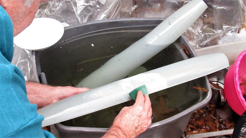
Final step here was to scrub the parts with fresh water to remove all soap, set the work aside to air-dry. and move on to other operations awaiting me in the shop.
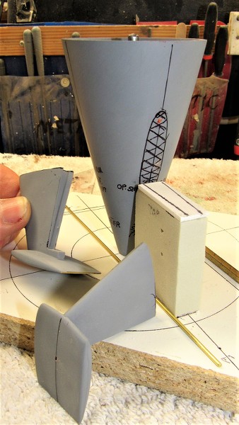
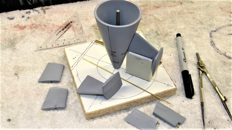
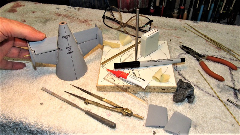
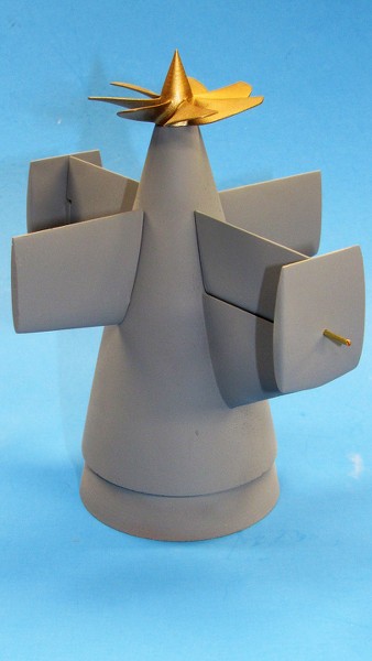
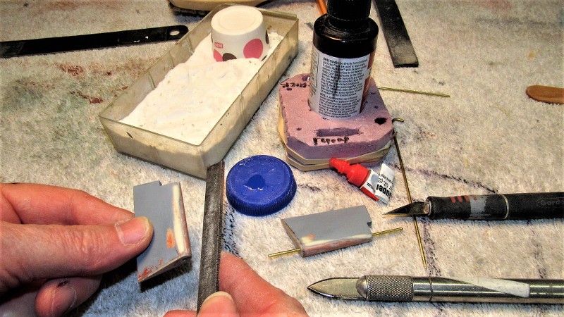
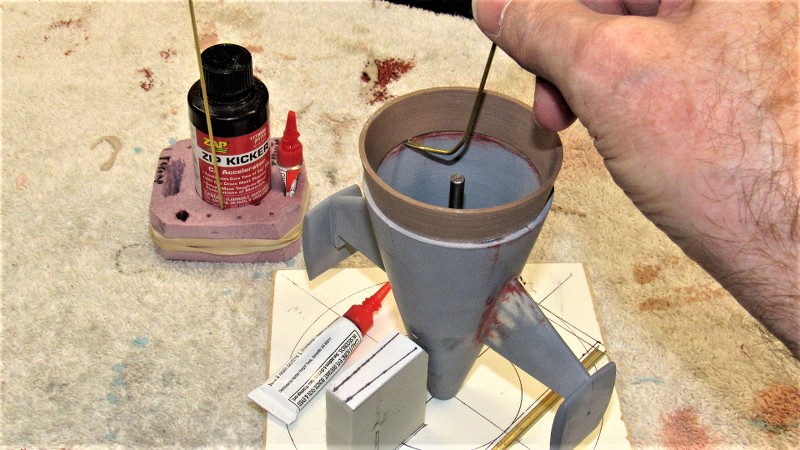
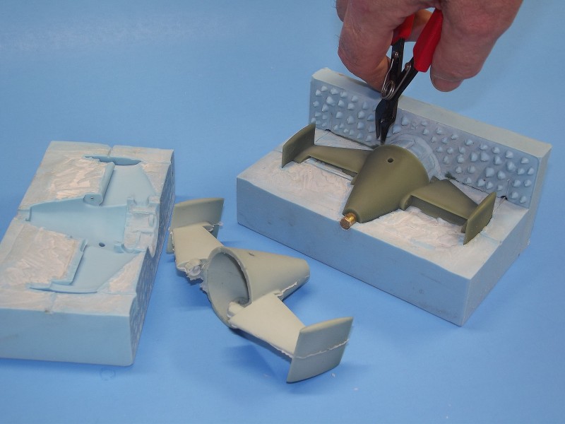
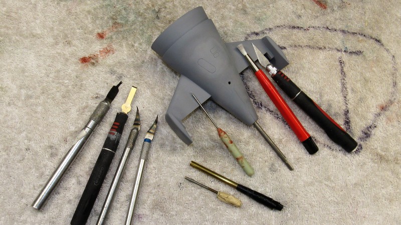
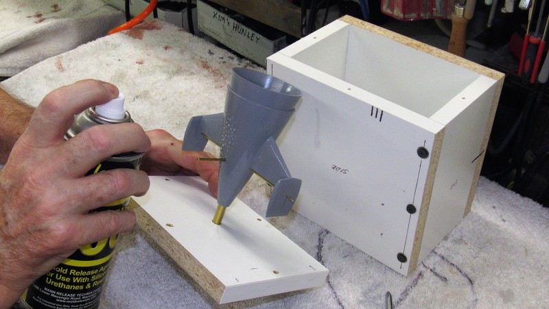
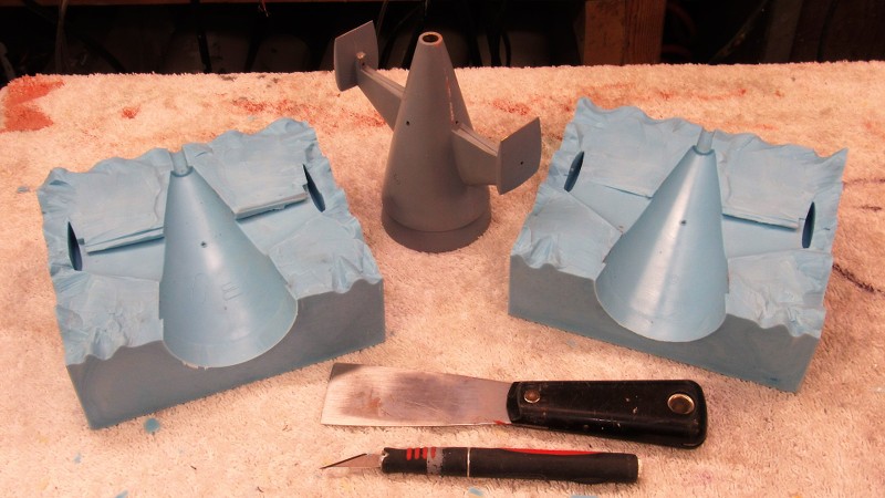
The tail-cone master marking/assembly jig was used to permanently mount the horizontal-vertical stabilizer assemblies to the tail-cone blank I had formed previous to the hull lay-up work. The jig insures a near perfect symmetry of the two stabilizers to the tail-cone; providing a positive means of suspending a stabilizer assembly against the side of the tail-cone as CA was applied to tack the pieces together.
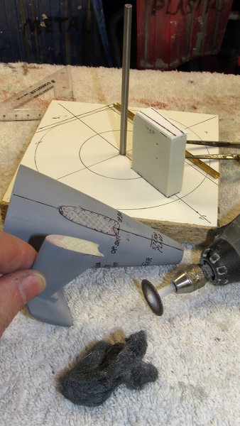
A RenShape 'crutch' atop the surface of the jig held a stabilizer assembly at the correct angle and height. In order to outline the area of the tail-cone the root of a stabilizer assembly would cover I hand-held a stabilizer and inked its outline onto the tail-cone.
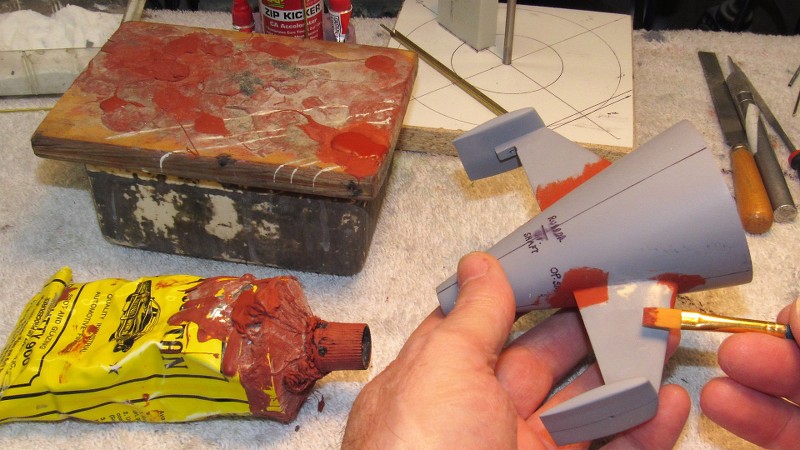
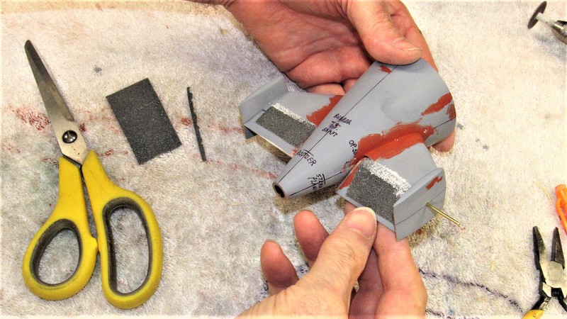
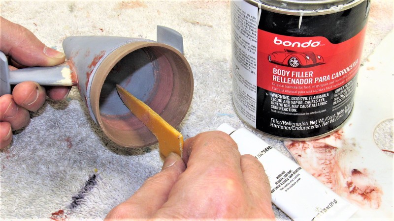
The root contact area of tail-cone and stabilizer assembly were roughed up with a cut-off wheel to increase the glue contact area during final assembly.
The jig insures repeatability and accuracy of assembly between parts, and is the only way I know of that will insure symmetry of spacing between like items, as well as correct orientation to one another about all planes of reference. This kind of work is not done by eye-ball alone. Often fixture and jig design and construction are more involved and take longer than the model parts themselves! Methodology, understanding of material physical and chemical properties, and a well structured chronology of events are key elements to successful model-building.
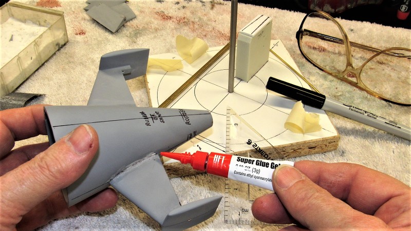
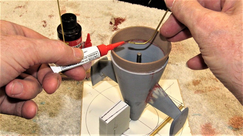
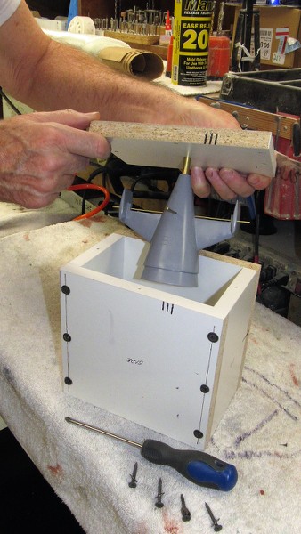
The stabilizer assemblies now tack glued to the tail-cone, the master was pulled away from the jig and CA added to the joints, letting capillary action to its work of wicking the glue into the gaps. Sprinkling on baking soda produced a hard grout that quickly cured. Riffler files and spot applications of CA-baking soda, followed by more careful filing, made tight the seams between stabilizers and tail-cone.
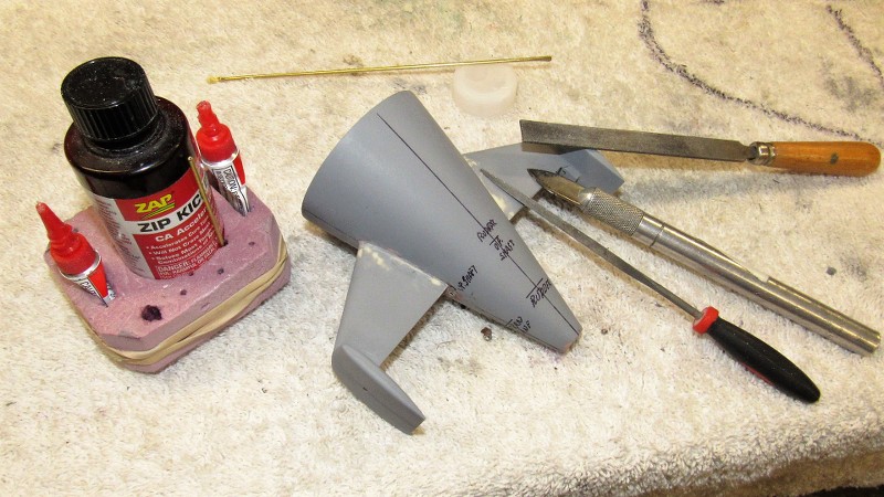
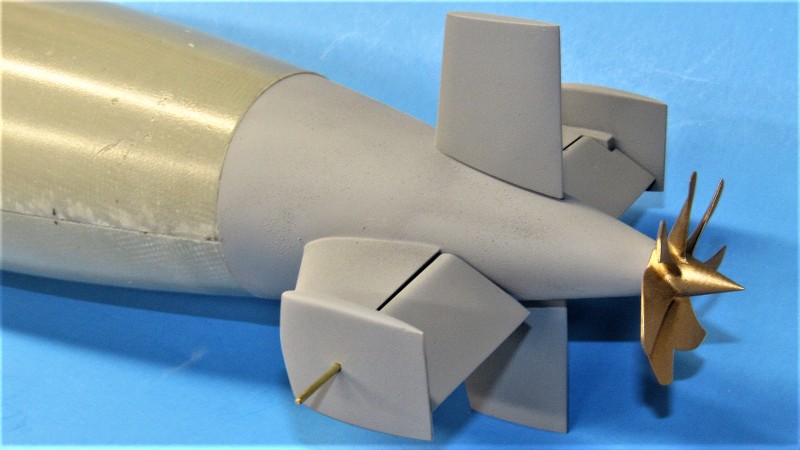
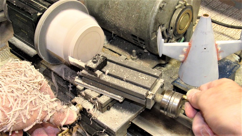
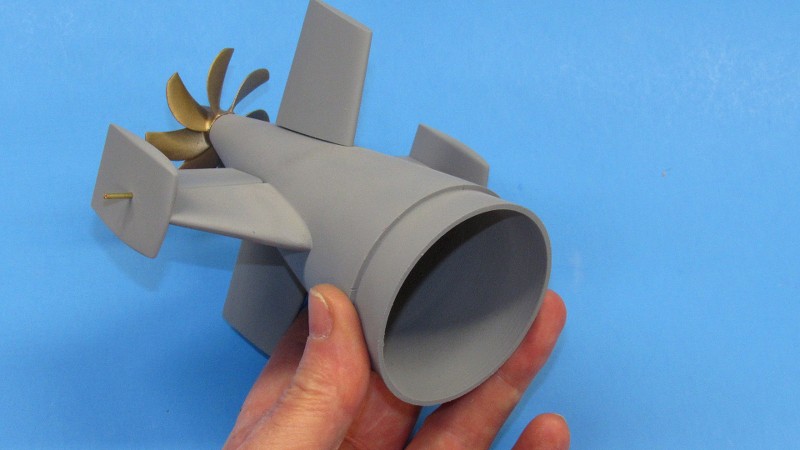
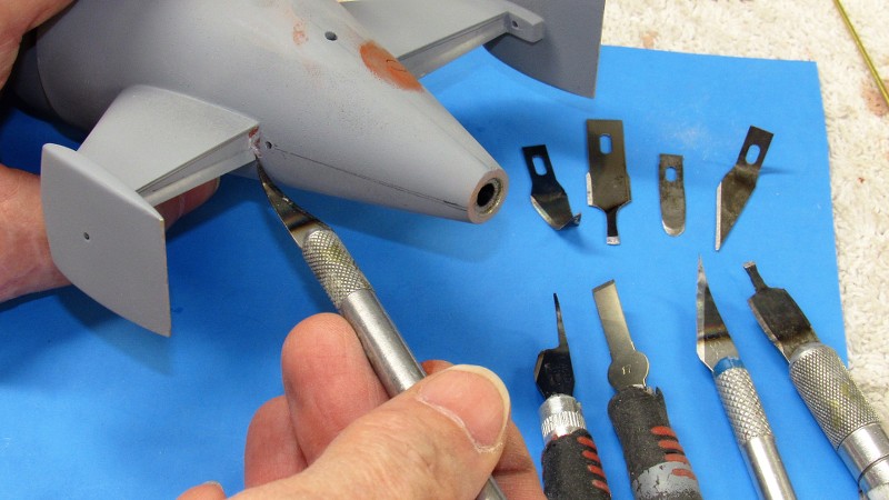
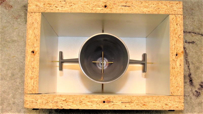
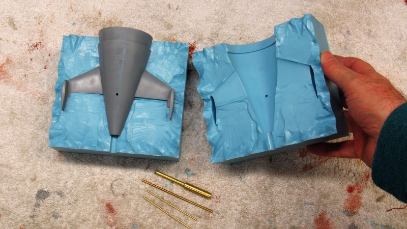
Before assembly I had drilled holes where the operating shafts of the stern planes would pass into the tail-cone. Here I'm checking for unbinding fit of a 1/16" diameter brass operating shaft stand-in to affirm I will have free operation of the stern planes. The bearing points for the operating shafts are at the vertical stabilizers outboard, and the tail-cone inboard.
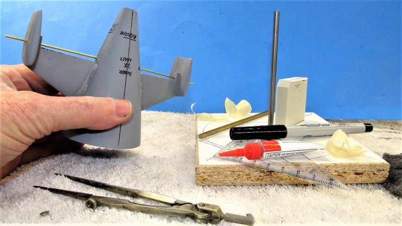
And a test-fit of the stern plane masters to check fit and clearance of the planes to the stabilizers and tail-cone.
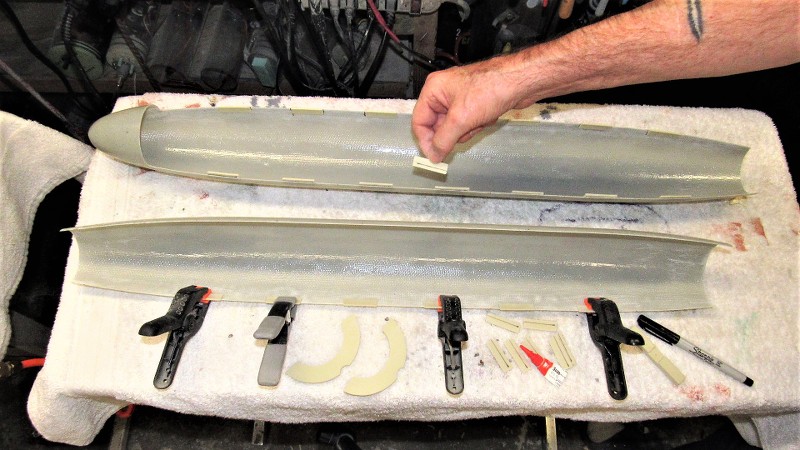
Continuing to turn the initial work on this kit into a practical 'demonstrator' I went about the task of producing the 'Z-cut' employed by many r/c submarine drivers to access the interior of their model to get at the inner workings. Typically the Z-cut is made by attaching a bow portion from the lower hull to the upper hull, and attaching the upper hull stern piece to the lower hull. The eventual cast resin tail-cone assembly will take care of the stern. Here, I'm attaching the lower hull bow piece to the upper hull.
I used the radial sonar dome engraved line as the demarcation line were I would separate the lower hull bow. A low-kerf cut-off wheel did the job well and I prepared the upper hull for attachment by gathering the adhesives, reinforcing glass tape, and tools needed to perform the transplant surgery. At this stage I roughed up the insides of the bow pieces and hull to insure good adhesion of the reinforcing glass tape.
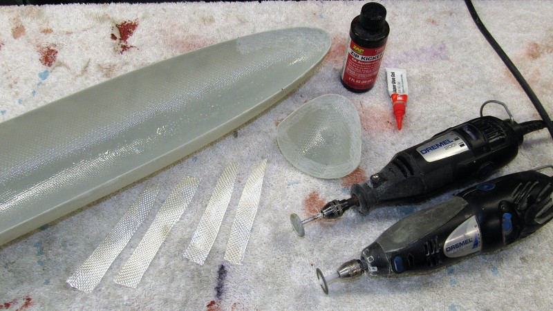
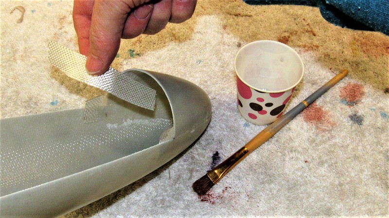
The lower bow was tack-glued to the upper hull with CA, then ten-ounce glass cloth strips were laminated across the seam on the inside of the hull. Nothing to it! The same West System epoxy laminating resin used for glass lay-up was used to saturate and bond the glass tape to the inside of the hull.
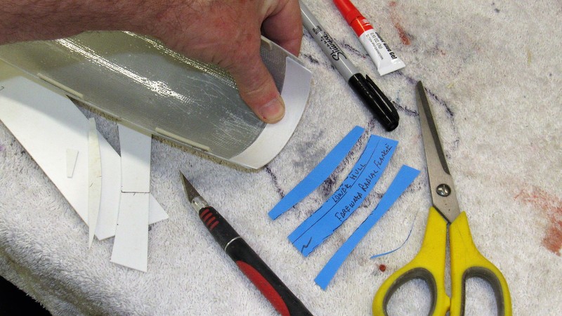
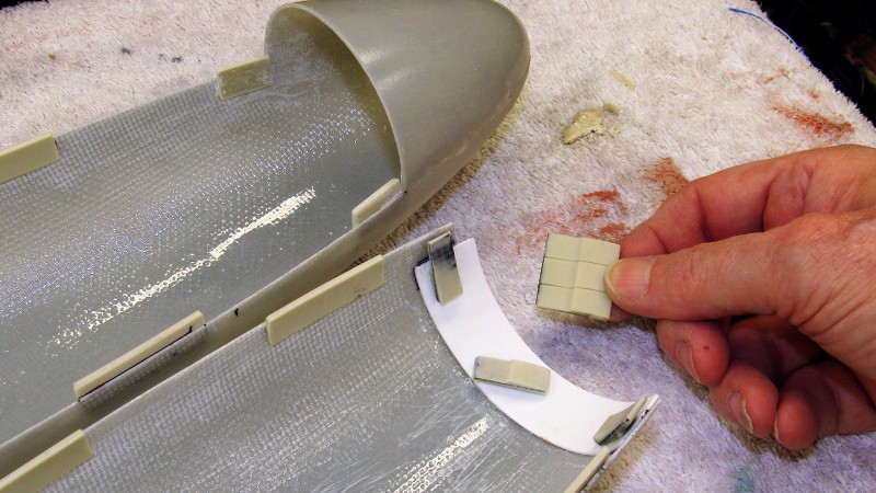
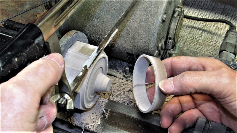
The marvel of the Z-cut is that only one, small mechanical fastener, aft, is all that is needed to secure the assembled hull halves together. But, a capture lip -- a radial flange -- within the forward edge of the lower hull has to be provided. This radial flange was first mocked up in cardboard, and once happy with it, the template was used to mark out a piece of .060" thick styrene sheet.
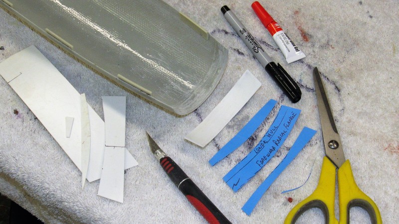
Nice thing about most thermoplastics is that they can be work-weakened to assume an awesome simple curve if needed. I did this with the radial flange piece by pinching it between a dowel and thumb as I pull it along at an angle. The curved flange was set in place within the lower hull. About 1/4" of it projecting forward past the end of the hull. It was CA'ed in place.
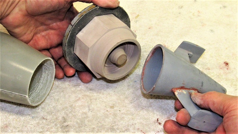
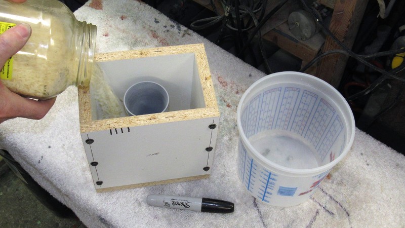
To insure that the removable hull halves would key together tightly I installed resin ' indexing tabs' within each hull, slightly raised above the longitudinal edges so that the assembled hull would fit with the longitudinal edges in near perfect alignment. These cast resin items attached within the hull halves with CA adhesive.
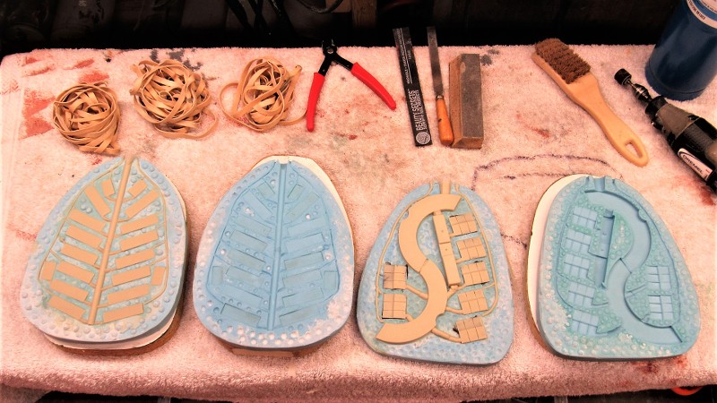
Fortunately, both the THRESHER and STURGEON class submarine had the same diameter and pretty close hull form. So, I dug out the tooling I had prepared for a THRESHER kit I authored a few years back, and pressed those into service to produce the indexing tabs, capture lips, WTC saddles, and Velcro foundation pieces needed for this STURGEON model. Sometimes fortune smiles...
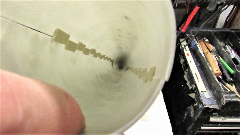
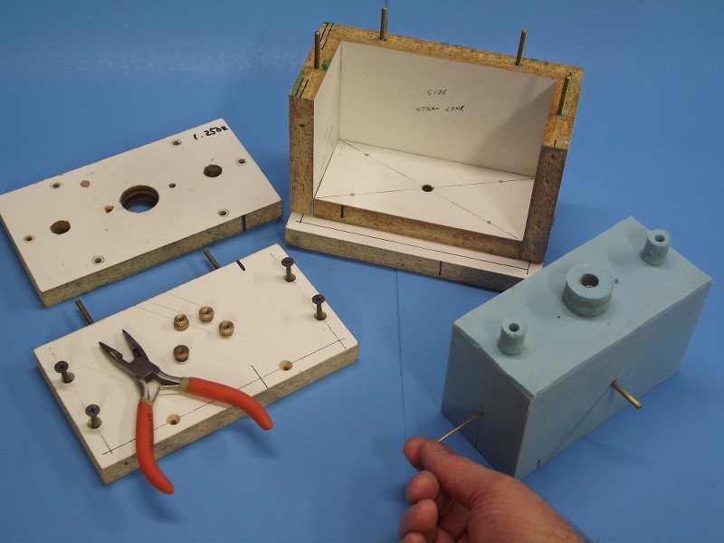
Here's how the staggered indexing tabs interlock to keep the upper and lower hull halves in alignment. We're looking through the opening at the stern, where the eventual tail-cone assembly will be bonded to the lower hull.
Supplementing the radial flange and indexing tabs at the bow were two carbon fiber reinforced capture lips. These interlock with the indexing tabs to pull the upper hull up tight against the radial flange of the lower hull.


Comment