-
Who is John Galt? -
Practical wisdom is only to be learned in the school of experience.
"Samuel Smiles"Comment
-
Russian Triton sub. Nice.Comment
-
Comment
-
David Douglass Merriman lll
835 Holly Hedge Ave.
Virginia Beach, Virginia 23452
US of *** A
dmeriman@aol.com
third from the sun
Sol system
Milky Way
Half-way out from the Big BangLast edited by He Who Shall Not Be Named; 02-25-2021, 07:25 PM.Who is John Galt?Comment
-
Russian midget
Nozzle functions as you indicated
I already worked out a linkage, it will be included, it is partly external of the hull.
It would be great to have a second opinion, maybe you see possibilities to have it all concealed within the hull perimeters.
Imo the latter will be too complicated to maintain for a novice person.
You can destroy it after you have a look at it David, how is that for a friendship gift, smashing up a pooped out gizmo?
Heat is also a PLA killer.
Grtz,
Bart
Practical wisdom is only to be learned in the school of experience.
"Samuel Smiles"Comment
-
I love it.
When it gets here I get to play Rube Goldberg (my personal Savior)
When I've worked out a credible linkage I get to destroy that 3D printed spawn of Satin with a Martian heat-ray I have left over from another consulting job.
Life is good!Who is John Galt?Comment
-
Thank you for my morning tea video. Life makes sense again David. I bought a 3D printer. It was never sent. I was out a few 100 bucks but saved from the demon. I took it as an omen. Never tried to get one again. My built in 3D printer managed this OK.Comment
-
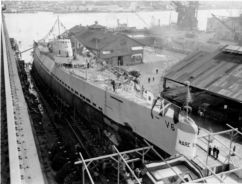
Last year the great hull fabricator, Richard O'Malley and I agreed to work up USS NAUTILUS (SS-168) kits so we can jointly terrorize the skimmers providing target services at the NC 'fleet-run'. Richard is well underway on the hull, and I've just started work on the appendages. Here's my contribution so far:
My work started after receiving a beautiful orthographic drawing of the NAUTILUS prepared by the Polish historian, Stawomir Brzezinski for Richard. I checked it against my sources and was delighted to see that Stawomir had likely used the BuShips 'Booklet of General Plans' as source -- most aspects of those documents were in agreement. A real confidence builder.
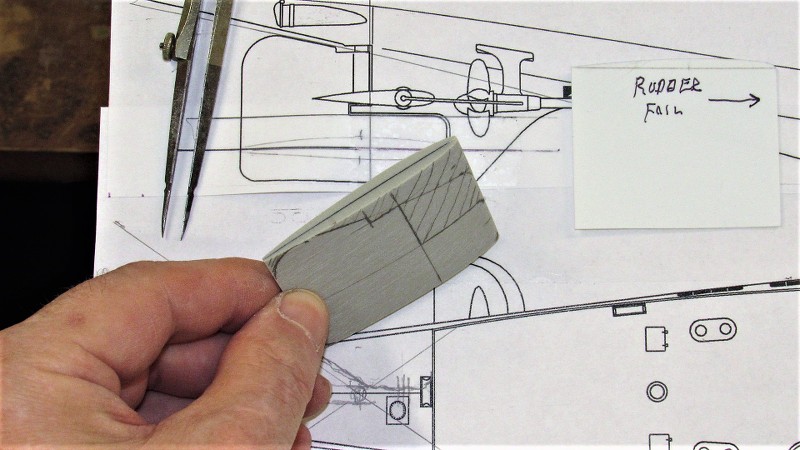
A very good start; Richard had secured the 'good stuff'! While Richard was doing his magic to produce the 1/96 hull master I set to work on the appendage masters. The list of things to make included: bow planes, sail, shears, guns, stern planes, rudder, and gun-deck. Today I stated with slapping together the RenShape blanks for the rudder, bow planes, and stern planes.
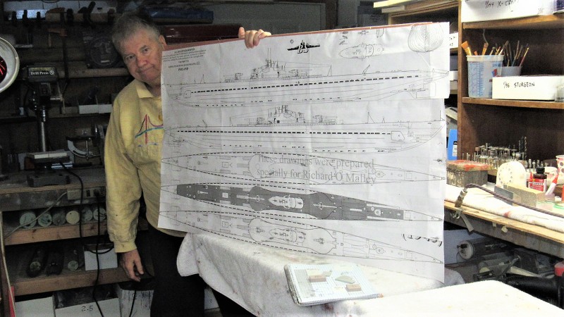
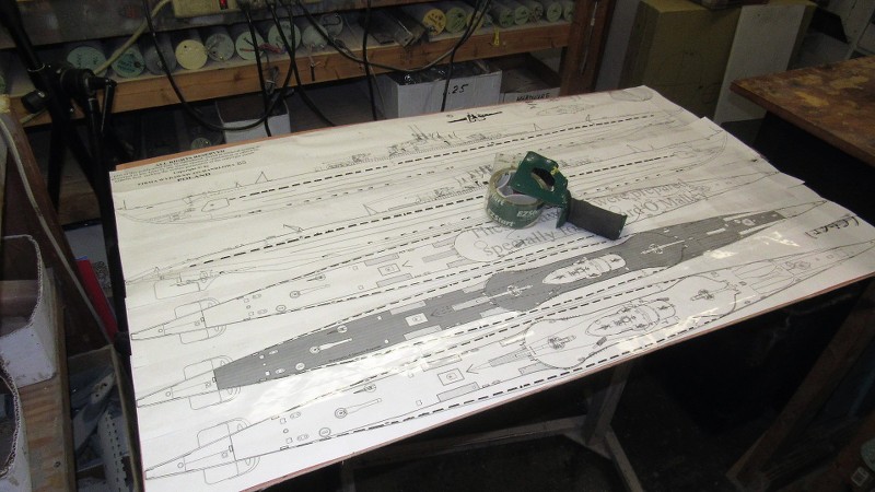
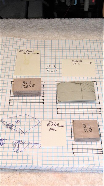
As is my practice I mount the drawings on a 'billboard' that will keep the documents flat for accurate lofting. The billboard permits me to move, in mass, all the orthographic documents relevant to the job around the shop or to just to get the damned thing out form under foot when it's not needed. Sorry about the fruity sweater, a joke birth-day gift by my smart-ass daughter! She's been a button-pusher from day one.
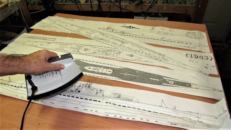
As Richard sent me the plans folded I had to iron them out to eliminate the creases. I also cut away dead space to reduce the total footprint of the plans. That work done I secured the drawings to the billboard with clear packaging tape. Now: to work!
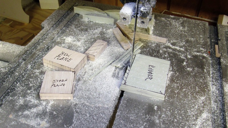
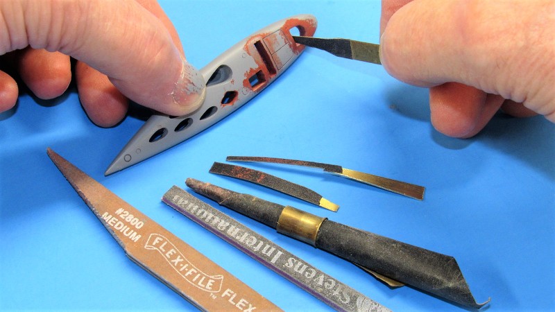
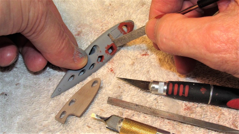
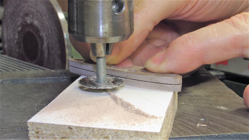
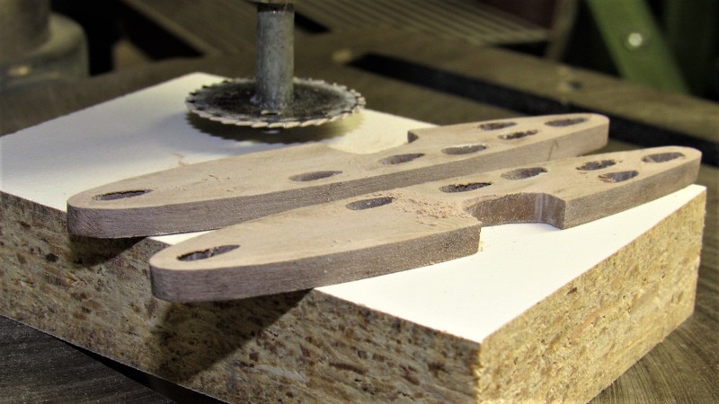
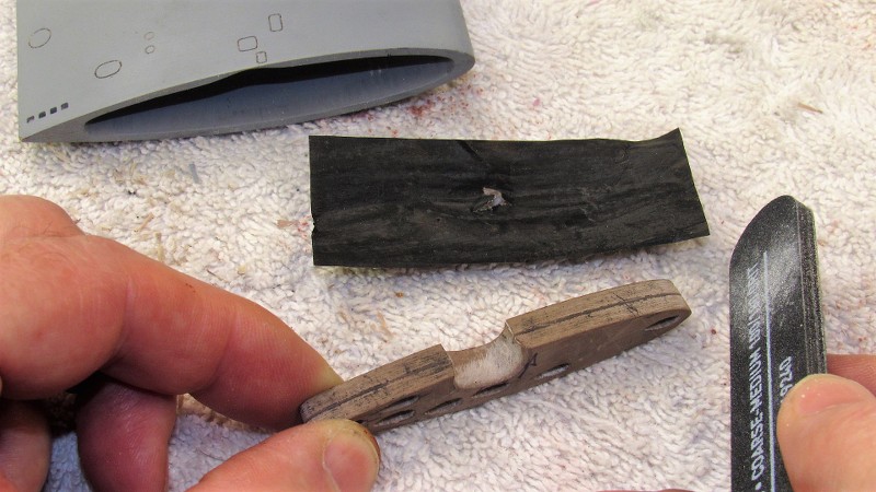
The ideal modeling medium is RenShape, for detail I use the medium-hard 40 lbs. per cubic foot stuff. I broke out a box of end cuts and worked some of it on the band-saw to come up with the control surface master blanks.
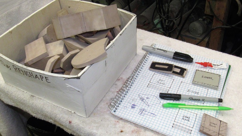
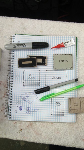
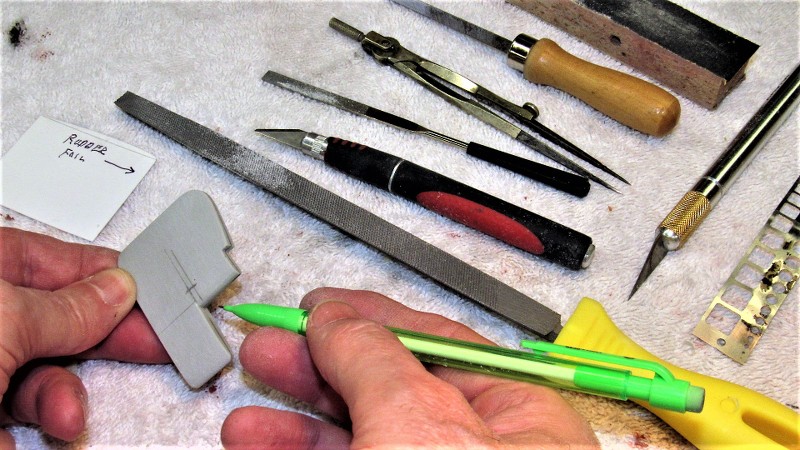
When shaping symmetrical structures it's wise to laminate two halves of a blank together after darkening their glue-side faces with black marker or paint. Doing so, no matter how much material you work away from the edges, you always have the centerline evident to guide you as you work both sides to the correct section -- in these masters, a tear-drop shaped hydrofoil.
Screw it. Enough. I'm hitting the rack!
Who is John Galt?Comment
-
Looking forward to this build!Comment
-
A brief recap on the 1/96 STURGEON master and tooling work I'm doing for the Nautilus Drydocks in support of the kit they will be coming out with in a few short months.
Keep in mind that this installment has little do do with the master and tooling work, but instead chronicles the work I've done so far on the 'check-model' I'm building to affirm the fit and detail capturing of parts produced from production tooling.
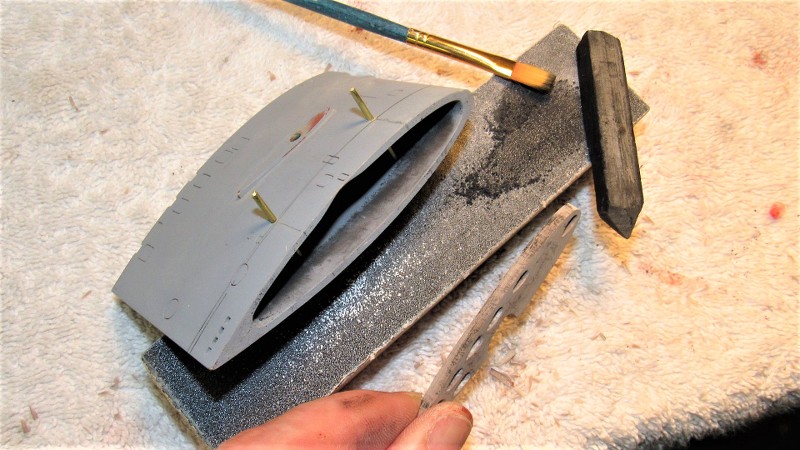
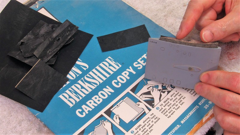
Previously I had bonded the resin tail-cone to the GRP lower hull. And that left me with the task of fairing in the radial seam between the two structures, initially with Bondo. After sanding that smooth, I switch to Nitro-Stan air-dry touch-up putty, sanded that, and then sprayed on the first check pass of gray primer.

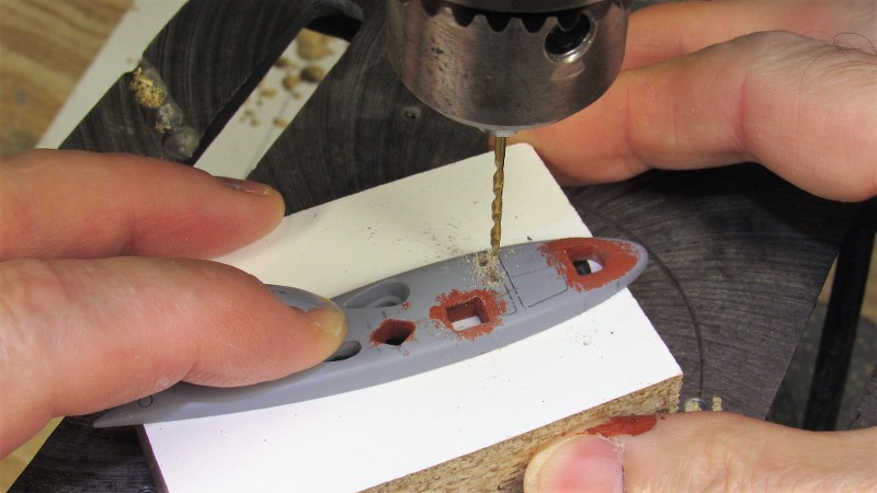
I didn't bother priming everything, just the recently opened up holes in the bottom and upper hull halves, as well as the before mentioned after radial break between stern-cone and lower hull; and the forward radial flange of the forward hull. The gray primer identified flaws that required filing or filling, and the process repeated.

Radial seam? What radial seam? I don't see no radial seam!


I was glad to see that the fine engraving I had applied to the hull master was not only faithfully captured in negative by the glove-mold, but was also imparted faithfully onto the check-model. Can't do engravings that deep and narrow with a hard-shell type tool.

Who is John Galt?Comment
-
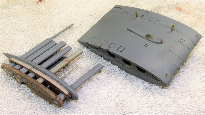
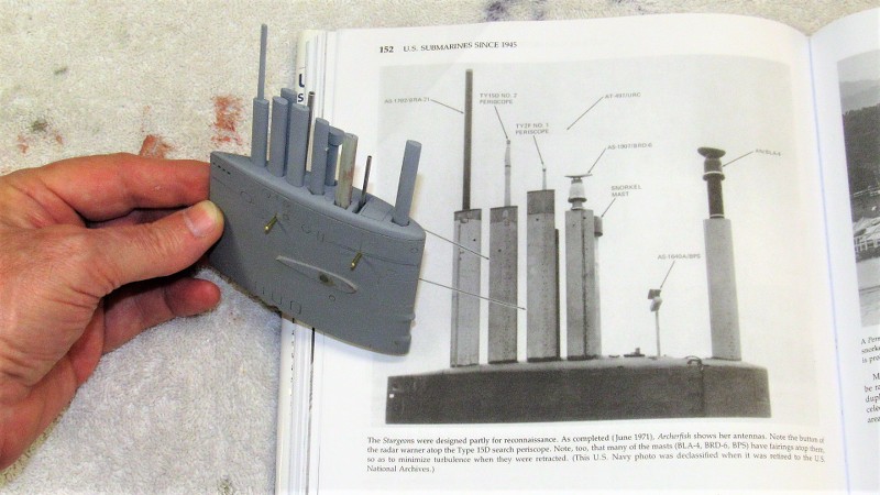
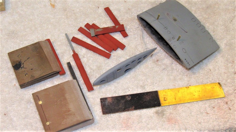
I always endeavor to make a model submarines sail as interesting as possible. That means representing all or most of the boats extendable masts and fairings as possible. You see that done on these models I did, both in 1/96 scale -- like the STURGEON masters and tooling I'm working on now. The finished one showing THRESHER, the unfinished one the WEBSTER (my second boat to have served on).
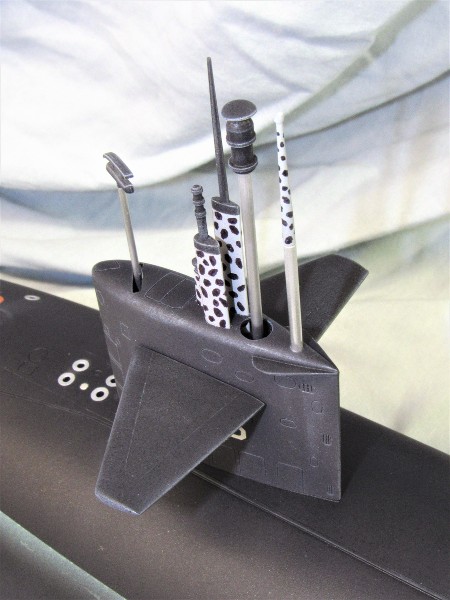

I install the masts and fairings when the model is on display, but will leave them on if I'm to operate the boat in 'safe' waters -- that is to say, I'm not running through surface formations and acting the fool as I play cat-and-mouse. If I'm froggy I leave the removable items in the tool-box and put a single 'sacrificial' mast on the sail I have something to see when tooling around at periscope depth.
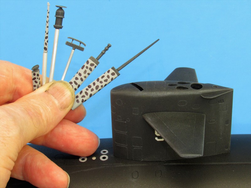
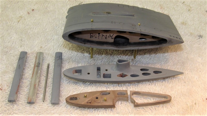
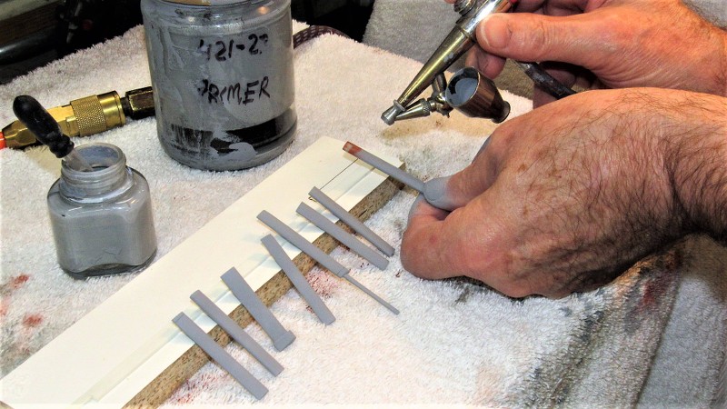
If the masts and fairings are to be removable AND are to all stand tall and straight each has to be support at two points. Typically a mast or fairing is supported at the top of the sail (or a point just within the opening at the top through which the mast would project), and another fixed support structure farther down in the sail. I've found the minimum distance between these two bearing points to be one-half-inch.
I'm tired, it's late, I'm hitting the rack... you got questions about how I do it? Ask! Here are the pretty pictures.
Nighty, night!

Who is John Galt?Comment


Comment