today's work

Collapse
X
 
  • Time
  • Show
Clear All
new posts
  • He Who Shall Not Be Named
    Moderator
    • Aug 2008
    • 12254


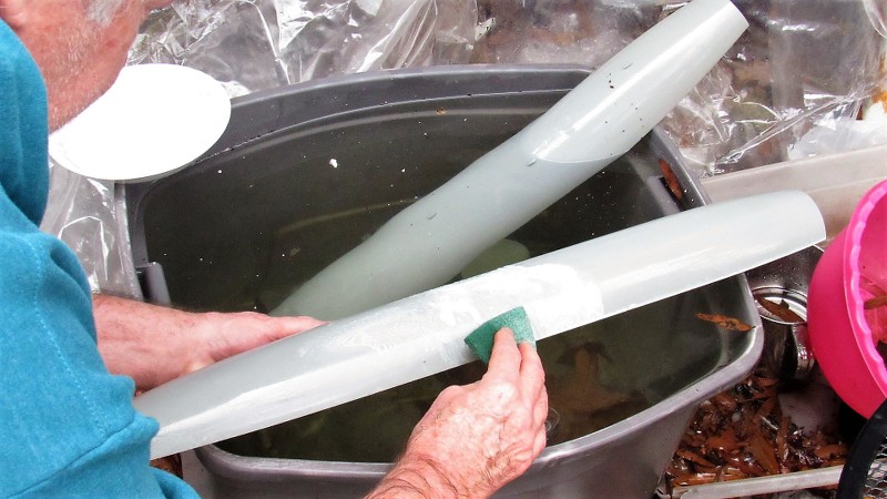
    Once the edges of the two GRP hull halves had been worked smooth, and the sterns -- where a tail-cone part would eventually reside -- had been chopped off and trued to the radial outline, It came time to dissolve off the protective PVA part-release the two GRP hull halves picked up during the lay-up process. This done with the most powerful solvent on this planet: fresh water!

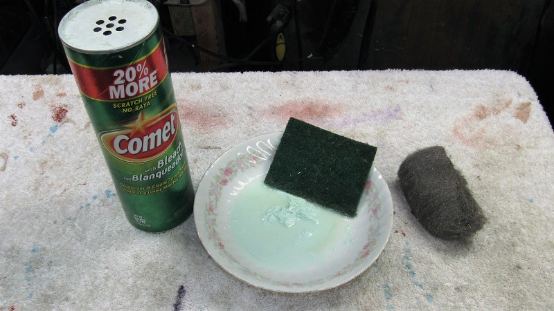
    Killing two birds with one stone I mixed up a slurry of water and abrasive laden 'cleanser' powder. This would, when rubbing down the GRP parts with an abrasive pad, not only insure that all the PVA was removed from the parts, it would also produce on the gel-coat surface microscopic abrasions that would produce the tooth needed to insure proper adhesion of glues, fillers, putties, and primer.
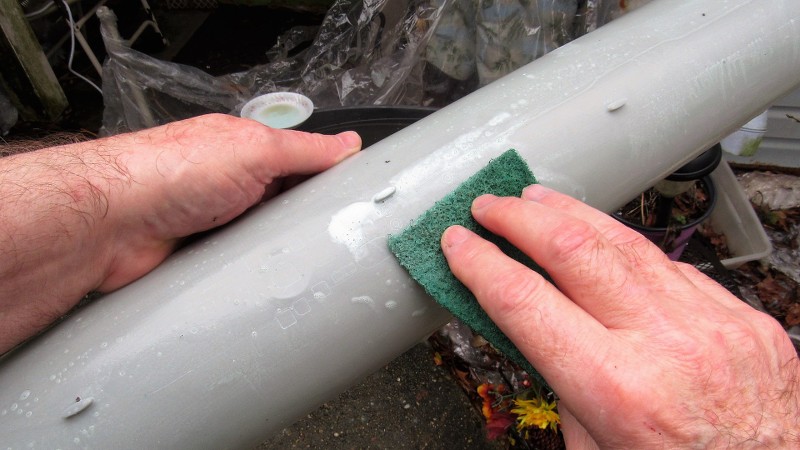


    Final step here was to scrub the parts with fresh water to remove all soap, set the work aside to air-dry. and move on to other operations awaiting me in the shop.


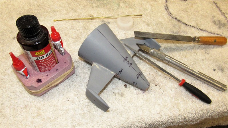
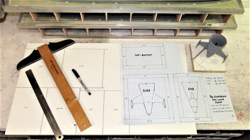
    The tail-cone master marking/assembly jig was used to permanently mount the horizontal-vertical stabilizer assemblies to the tail-cone blank I had formed previous to the hull lay-up work. The jig insures a near perfect symmetry of the two stabilizers to the tail-cone; providing a positive means of suspending a stabilizer assembly against the side of the tail-cone as CA was applied to tack the pieces together.

    A RenShape 'crutch' atop the surface of the jig held a stabilizer assembly at the correct angle and height. In order to outline the area of the tail-cone the root of a stabilizer assembly would cover I hand-held a stabilizer and inked its outline onto the tail-cone.
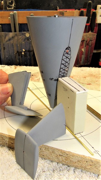


    The root contact area of tail-cone and stabilizer assembly were roughed up with a cut-off wheel to increase the glue contact area during final assembly.
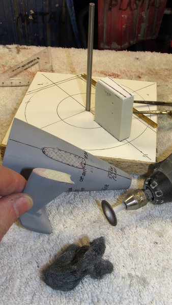


    The jig insures repeatability and accuracy of assembly between parts, and is the only way I know of that will insure symmetry of spacing between like items, as well as correct orientation to one another about all planes of reference. This kind of work is not done by eye-ball alone. Often fixture and jig design and construction are more involved and take longer than the model parts themselves! Methodology, understanding of material physical and chemical properties, and a well structured chronology of events are key elements to successful model-building.
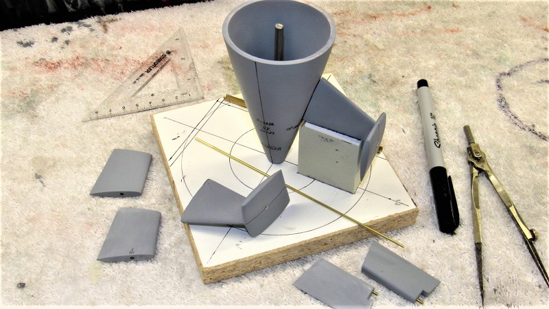


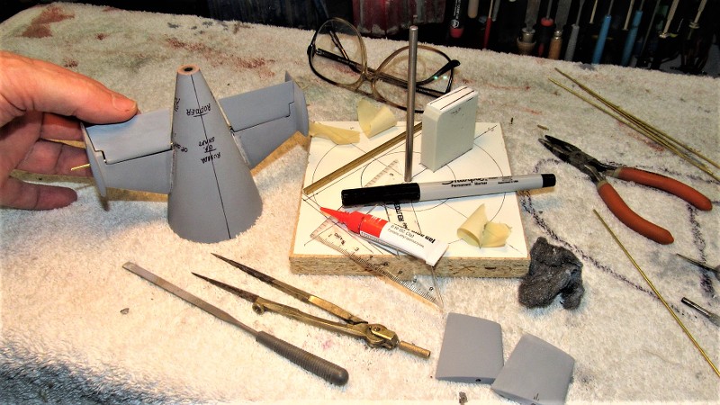
    The stabilizer assemblies now tack glued to the tail-cone, the master was pulled away from the jig and CA added to the joints, letting capillary action to its work of wicking the glue into the gaps. Sprinkling on baking soda produced a hard grout that quickly cured. Riffler files and spot applications of CA-baking soda, followed by more careful filing, made tight the seams between stabilizers and tail-cone.
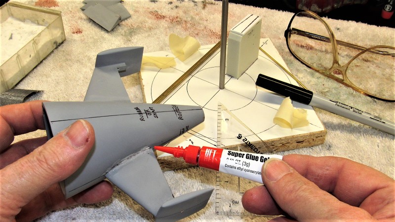


    Before assembly I had drilled holes where the operating shafts of the stern planes would pass into the tail-cone. Here I'm checking for unbinding fit of a 1/16" diameter brass operating shaft stand-in to affirm I will have free operation of the stern planes. The bearing points for the operating shafts are at the vertical stabilizers outboard, and the tail-cone inboard.
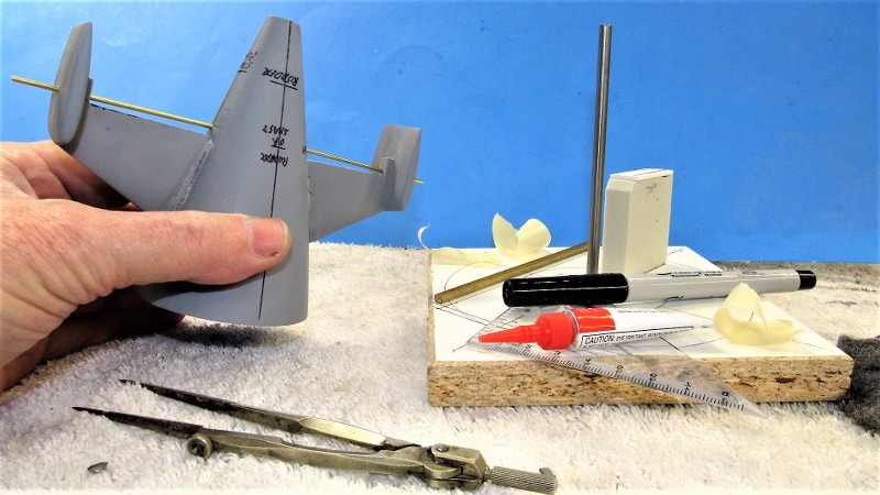


    And a test-fit of the stern plane masters to check fit and clearance of the planes to the stabilizers and tail-cone.


    Continuing to turn the initial work on this kit into a practical 'demonstrator' I went about the task of producing the 'Z-cut' employed by many r/c submarine drivers to access the interior of their model to get at the inner workings. Typically the Z-cut is made by attaching a bow portion from the lower hull to the upper hull, and attaching the upper hull stern piece to the lower hull. The eventual cast resin tail-cone assembly will take care of the stern. Here, I'm attaching the lower hull bow piece to the upper hull.

    I used the radial sonar dome engraved line as the demarcation line were I would separate the lower hull bow. A low-kerf cut-off wheel did the job well and I prepared the upper hull for attachment by gathering the adhesives, reinforcing glass tape, and tools needed to perform the transplant surgery. At this stage I roughed up the insides of the bow pieces and hull to insure good adhesion of the reinforcing glass tape.
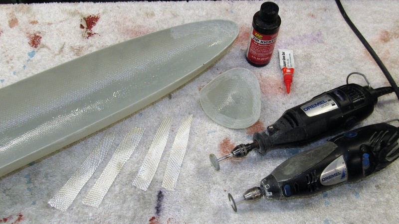


    The lower bow was tack-glued to the upper hull with CA, then ten-ounce glass cloth strips were laminated across the seam on the inside of the hull. Nothing to it! The same West System epoxy laminating resin used for glass lay-up was used to saturate and bond the glass tape to the inside of the hull.
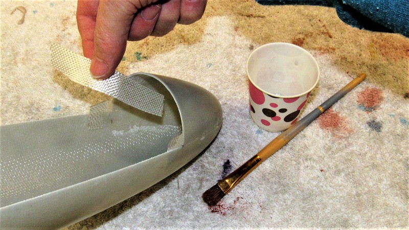


    The marvel of the Z-cut is that only one, small mechanical fastener, aft, is all that is needed to secure the assembled hull halves together. But, a capture lip -- a radial flange -- within the forward edge of the lower hull has to be provided. This radial flange was first mocked up in cardboard, and once happy with it, the template was used to mark out a piece of .060" thick styrene sheet.
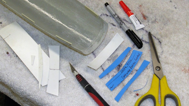


    Nice thing about most thermoplastics is that they can be work-weakened to assume an awesome simple curve if needed. I did this with the radial flange piece by pinching it between a dowel and thumb as I pull it along at an angle. The curved flange was set in place within the lower hull. About 1/4" of it projecting forward past the end of the hull. It was CA'ed in place.
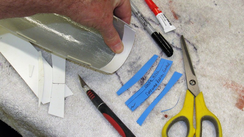


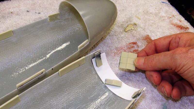
    To insure that the removable hull halves would key together tightly I installed resin ' indexing tabs' within each hull, slightly raised above the longitudinal edges so that the assembled hull would fit with the longitudinal edges in near perfect alignment. These cast resin items attached within the hull halves with CA adhesive.
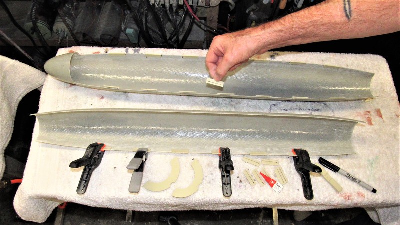


    Fortunately, both the THRESHER and STURGEON class submarine had the same diameter and pretty close hull form. So, I dug out the tooling I had prepared for a THRESHER kit I authored a few years back, and pressed those into service to produce the indexing tabs, capture lips, WTC saddles, and Velcro foundation pieces needed for this STURGEON model. Sometimes fortune smiles...
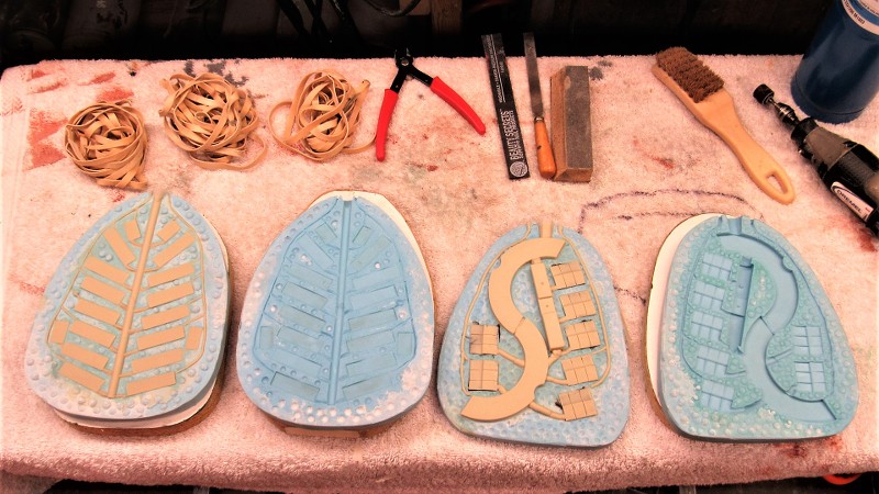


    Here's how the staggered indexing tabs interlock to keep the upper and lower hull halves in alignment. We're looking through the opening at the stern, where the eventual tail-cone assembly will be bonded to the lower hull.
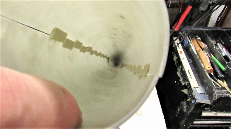


    Supplementing the radial flange and indexing tabs at the bow were two carbon fiber reinforced capture lips. These interlock with the indexing tabs to pull the upper hull up tight against the radial flange of the lower hull.

    Who is John Galt?

    Comment

    • rwtdiver
      Vice Admiral
      • Feb 2019
      • 1768

      David,

      I sure do enjoy sitting in my hobby room in the wee hours of the morning reading and looking at all your photos from your "Today's Work" blog! Everything you do just seems to fall into place so perfect! I really understand why, and that is just simply the years you have in this hobby and the total learning process that you have gone through to get to where you are at.

      It seems like everything I do I have to do over and over and then it still never looks quite right!! Looking at all your photos I see a lot of time consuming planning and patience in everything you do! I really think that it is an inborn trait that you and some of the other guys on this forum have!

      Thanks David! I appreciate all your knowledge and the fact that you share it all with us!

      Rob
      "Firemen can stand the heat"
      Words to live by: "Perfection is our goal. Excellence will be tolerated"

      Comment

      • RCSubGuy
        Welcome to my underwater realm!
        • Aug 2009
        • 1768

        Originally posted by rwtdiver
        Looking at all your photos I see a lot of time consuming planning and patience in everything you do! I really think that it is an inborn trait that you and some of the other guys on this forum have!
        That is the secret sauce, right there! When working on these boats, you need to think not only about the step that you're on, but what step you'll be needing to think about three steps from now. I don't know how many times I've installed something only to have it interfere with another part or linkage path and having to redo it all. If there is one thing that getting my pilot's license has taught me is that you need to think about not only what you're doing, but what you have to do ten minutes from now.

        Great stuff, as always, David! This is going to be a monumental kit once we get it out to everyone!


        Bob

        Comment

        • SteveNeill
          Commander
          • Apr 2020
          • 315

          Toys make the heart well! Better! And more fun! I'm so glad to see this! Carry on Sir!

          Comment

          • rwtdiver
            Vice Admiral
            • Feb 2019
            • 1768

            Originally posted by SubHuman

            That is the secret sauce, right there! When working on these boats, you need to think not only about the step that you're on, but what step you'll be needing to think about three steps from now. I don't know how many times I've installed something only to have it interfere with another part or linkage path and having to redo it all. If there is one thing that getting my pilot's license has taught me is that you need to think about not only what you're doing, but what you have to do ten minutes from now.

            Great stuff, as always, David! This is going to be a monumental kit once we get it out to everyone!


            Bob
            Thanks for the input Bob and Steve! Guess I am a little frustrated right now! Sorry I brought this into David's build blog! Time to move on!!

            Rob
            "Firemen can stand the heat"
            "Perfection is our goal. Excellence will be tolerated"

            Comment

            • He Who Shall Not Be Named
              Moderator
              • Aug 2008
              • 12254

              Originally posted by rwtdiver

              Thanks for the input Bob and Steve! Guess I am a little frustrated right now! Sorry I brought this into David's build blog! Time to move on!!

              Rob
              "Firemen can stand the heat"
              "Perfection is our goal. Excellence will be tolerated"
              I'm good with the posts -- thought and discussion starters always welcome, no matter where you stick them.

              David
              Resident Luddite
              Who is John Galt?

              Comment

              • SteveNeill
                Commander
                • Apr 2020
                • 315

                You motivate me to finish my type 23. Thank you!

                I'm just working to fill a bunch of masks orders, edit our weekly and subscriber shows, do interviews for books about my work and a bunch of other things like my darn J-3 Cub! I'll get there. Still have to test my Nautilus Drydocks Nautilus too! No one gets to die when you have this much stuff to do. And that's and order! Get busy men, this stuff is in fact life saving and important!

                Steve
                A Hollywood artifact that still lives and breathes

                Comment

                • He Who Shall Not Be Named
                  Moderator
                  • Aug 2008
                  • 12254


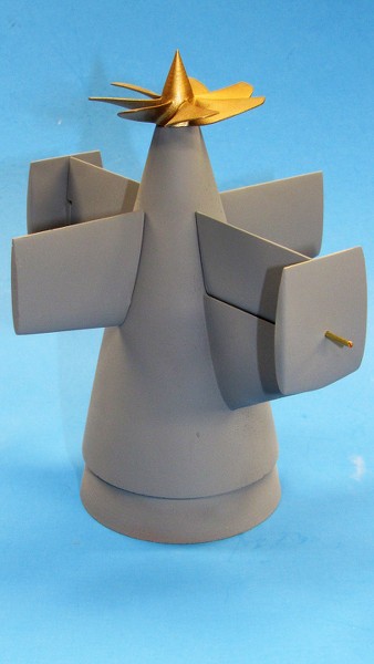
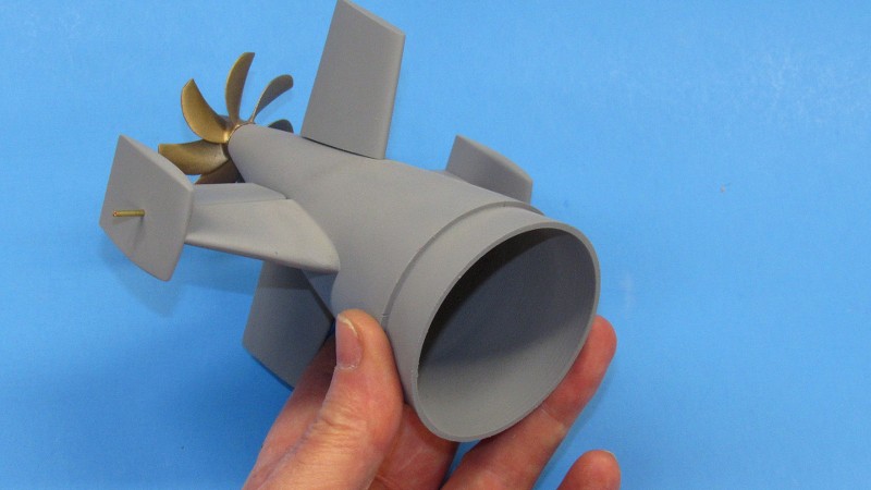
                  I'm pushing to complete the tail-cone master so I can make its tool and get on with production of cast resin parts.

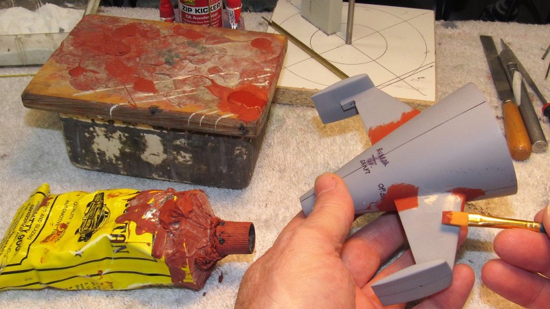
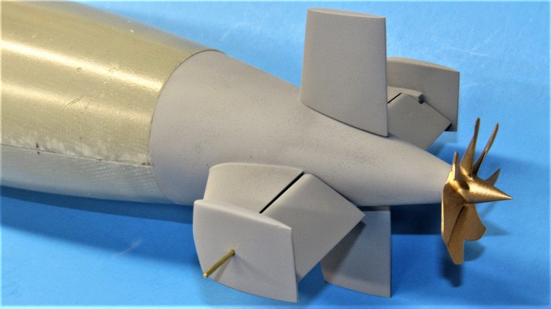
                  With this picture I jump ahead to show the finished product. Note the fidelity of the seam work between stabilizers and tail-cone; also note the uniform gap between stabilizer trailing edge and stern plane leading edge. The following work outlines how such magnificence was achieved. Gap filling was done in two stages: building up CA-baking soda grout to fill the gross gaps and filing that back; then filling the tool marks with air-dry Nitro Stan air-dry automotive lacquer putty, followed by careful wet-sanding.


                  The ideal tool for cutting in right angle joints and joints of negative draft is a three-face ******* cut file. It cuts quickly and if held correctly will not damage the adjoining work. The file must be cleaned periodically with a wire brush (file card) designed for the task. This work is done dry and the teeth will clog with only a few strokes. You can't clean a file too often! Any seam gaps revealed during this work were filled with CA and grout, and cut back with the file.


                  A flat second-cut file was used to remove most of the tool marks. I then applied air-dry putty to address the scratches. After that had dried, the seams were wet sanded with stiff sandpaper, starting with #220 and working up to #400. This work was done wet to keep the abrasive particles from clogging the abrasive.


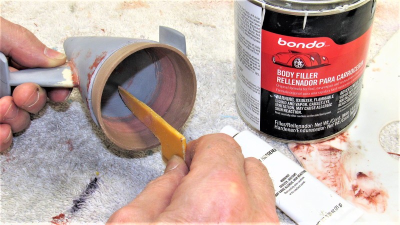
                  Unfortunately the stern plane leading edges did not describe a half-cylinder section at the leading edge. This had to be built up with Bondo filler and then worked with file until the proper shape had been achieved.

                  (Like a dumb-ass I failed to find this fault with the original master -- had I done so, I would have had to make only one fix, not two as was the case here -- **** Poor Planning Produces Pucked Product!).


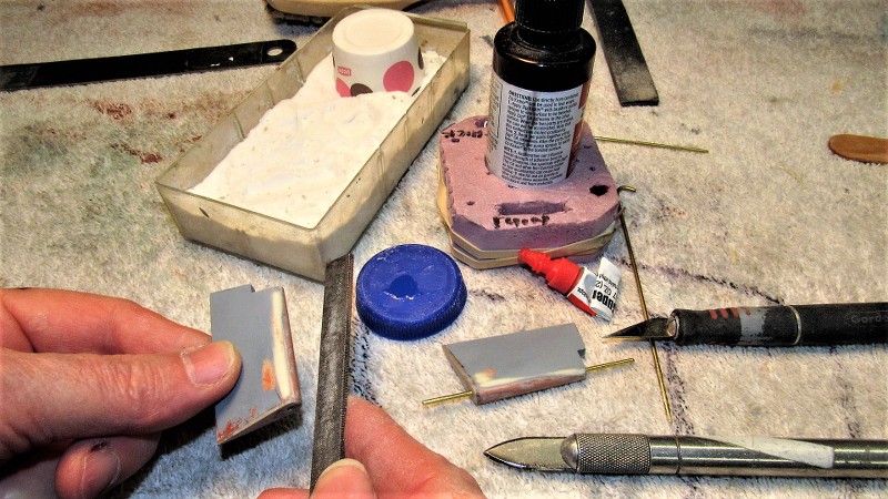
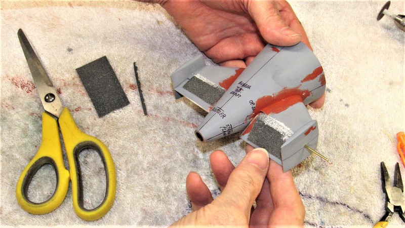
                  The gap between the assembled stern planes and horizontal stabilizers was too tight. I slipped a length of #200 sandpaper into the gap -- grit side against the stabilizer concave trailing edge -- and cycled the planes. This quickly, and uniformly, widened the gaps between stern planes and stabilizers. Finishing strokes were done with a layer of #400 sandpaper to smooth out the trench created.


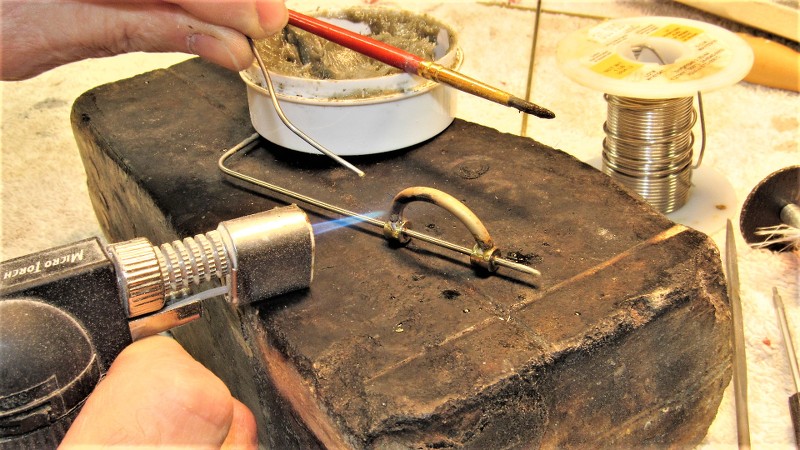
                  I needed to get away from that frig'n tail-cone job. So, I slapped together a yoke for the stern planes. This item makes up the inboard ends of the stern plane operating shafts so they can work uniformly. The yoke permits passage of the centrally running propeller shaft. Soldering 101. Wheel collars are my friend!


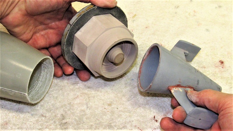
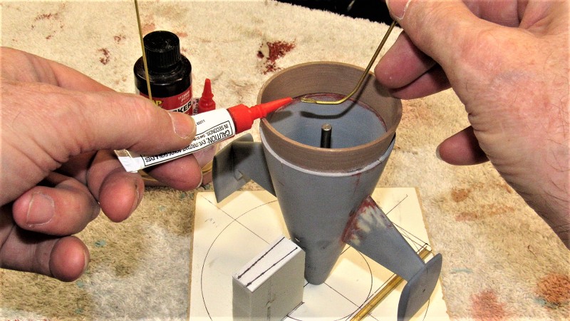
                  OK, back to this pain-in-the-ass tail-cone master: At the forward end of tail-cone is a radial flange that mates with the inside stern of the two hull halves when they are assembled. The tail-cone part (on an assembled model kit) is glued to the lower hull. The upper hull, when assembled, sits atop the tail-cone radial flange. A single mechanical fastener running through upper hull and radial flange secures the two hull halves together. Slick!


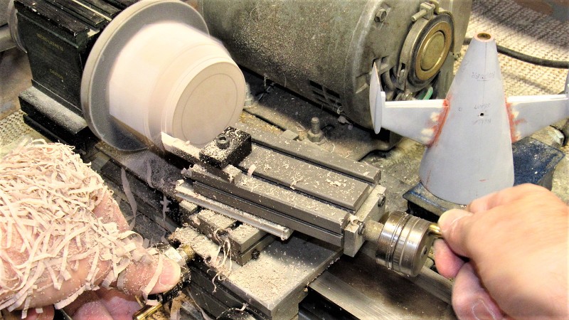
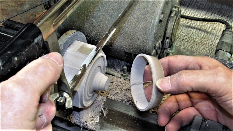
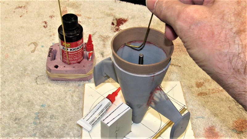
                  The radial flange was turned from a hunk of 40 pound-per-cubic-foot RenShape model-builders board. It was then CA'ed to the forward end of the tail cone.


                  There!! A little scribing work, a finish sanding, and I can get started in on the tool for this thing.
                  Who is John Galt?

                  Comment

                  • SteveNeill
                    Commander
                    • Apr 2020
                    • 315

                    Well done! Beautiful David.

                    Comment

                    • He Who Shall Not Be Named
                      Moderator
                      • Aug 2008
                      • 12254


                      With the 1/96 STURGEON tail-cone master nearing completion it came time to address how the three-piece rubber tool would be cast.

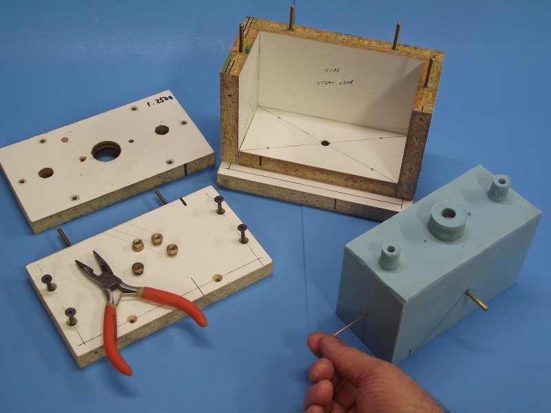
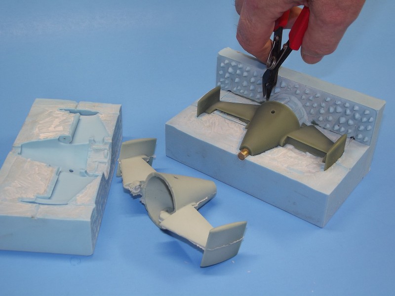
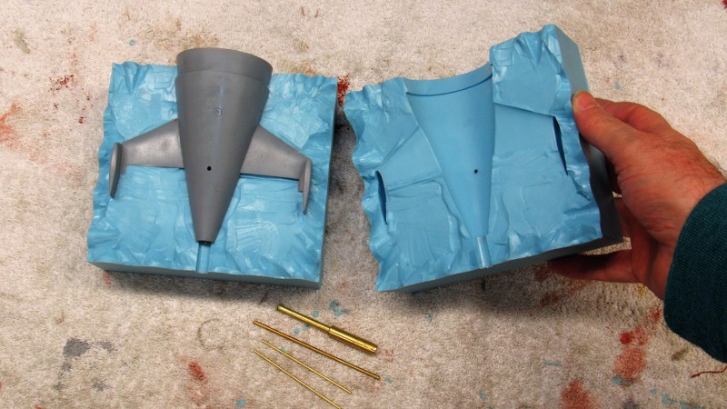
                      Here I'm showing the end-game of tail-cone tool making, using this 1/96 BLUEBACK tool as a fair representation of what the STURGEON tail-cone tool will look like.


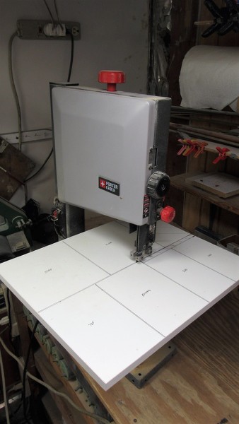
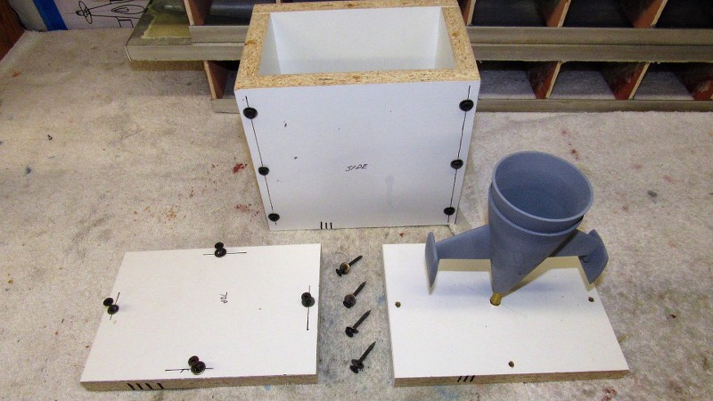
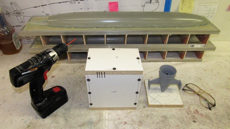
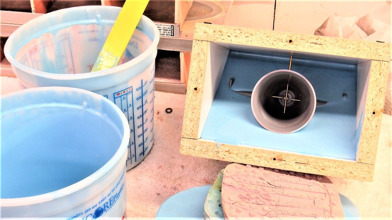
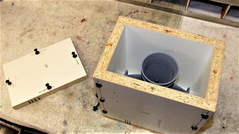
                      A flask -- a box-like containment that holds the liquid mold making RTV rubber in place as it changes state to a solid -- is constructed from 5/8" thick particle board 'shelving'. Later, during cast resin part production, this flask serves to hold the tool ridged and the three parts that constitute the tool held in perfect registration with one another


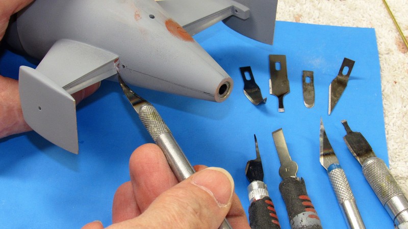
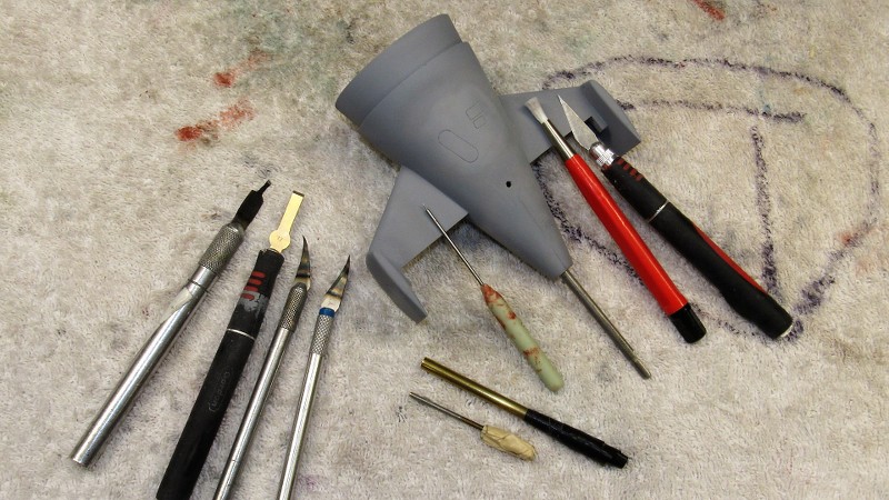
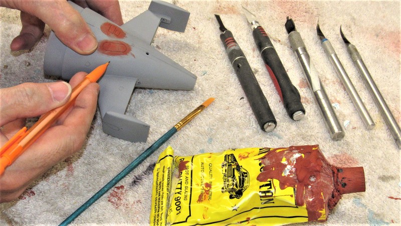
                      Some hard-to-get-at spots on the tail-con master -- such as the horizontal stabilizer trailing edge concave, where that trench joined the tail-cone and vertical stabilizer -- were best fine-tuned with special knifes made just for these type tasks.


                      These special knife blades were ground to the desired shape and sharpened, then bent after taking the blade to a red heat. Each started life as a common X-Acto knife blade, but altered to my specific need.


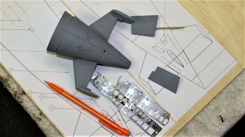
                      From the plan I lofted the engravings onto the master in pencil. Once happy with the lay-out I committed to the engraving tool


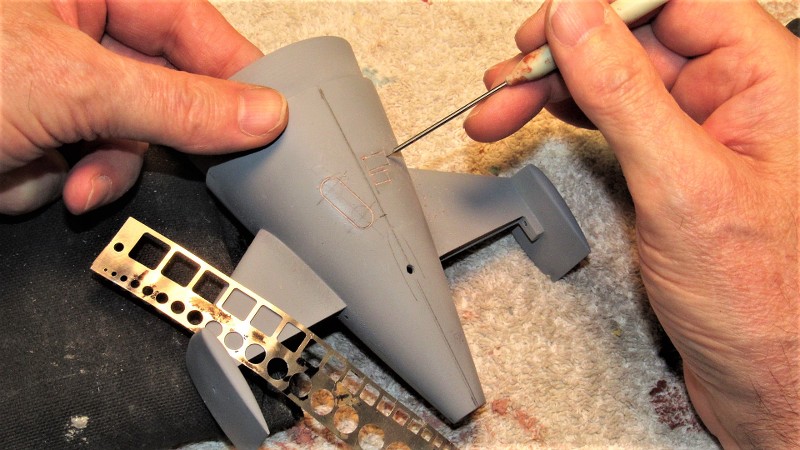
                      Scribing on the tail-cone master was a real chore. As I was engraving into four types of substrate -- GRP, Bondo, air-dry putty, and primer -- I had to take extreme care with the strokes of the scratch-awl as I cut into the surfaces, the engraving tool guided by stainless steel stencils.


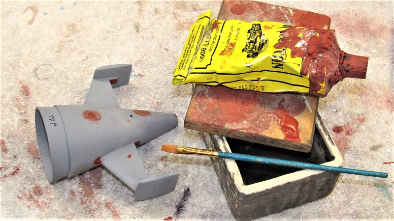
                      The hard to avoid boo-boo's with the scribing tool were addressed with air-dry putty and the problem areas again addressed with the scratch-awl. Once the scribe work was cleaned up I pencil marked all spots on that master requiring touch-up putty.


                      Air-dry putty was applied with a brush. To keep the quick-dry putty of a desired consistency I occasionally dipped the brush in some lacquer thinner and mixed up some putty till it was again brushable. Once the spot-putty had dried, those areas were wet-sanded, the master given a last coat of primer, and given a final dry-sanding with #400 sandpaper.


                      Who is John Galt?

                      Comment

                      • He Who Shall Not Be Named
                        Moderator
                        • Aug 2008
                        • 12254


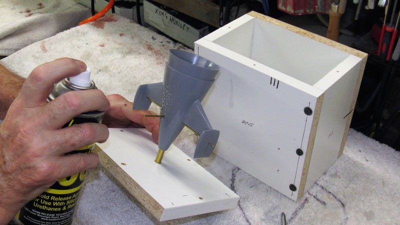
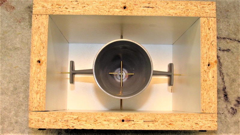
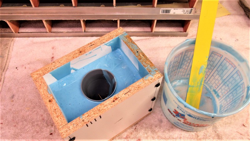
                        The completed tail-cone master was secured to the bottom of the containment flask with a 5/16" pin. This pin is the same diameter of the eventual Oilite bushings that will fit within the cast resin tail-cone piece. That bearing in turn accepting the propeller shaft. The pin you see here not only suspends the master within the flask so it can be properly encapsulated in rubber, it also produces the bore that will accept, during resin part pouring, another pin that will produce the Oilite bearing bore.

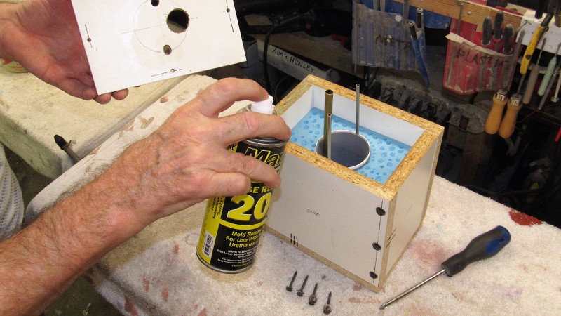
                        Here I'm applying Mann 200 spray-on mold-release silicon just before placing the master in the flask.


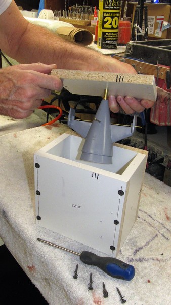
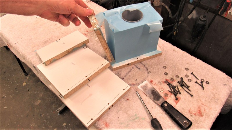
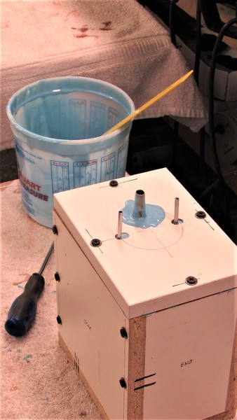
                        All six pieces of the flask have been indexed to insure it all goes together the same way. The pieces are secured with deck-screws -- this permits me to take the flask apart when it comes time to access the rubber tool for master extraction and later resin casting preparation and part removal.


                        Note the brass rods projecting from the sides of the tail-cone. These form bores within the tool that will accept rods that will create bores in the cast resin tail-cone parts to accept the rudder and stern plane operating shafts.


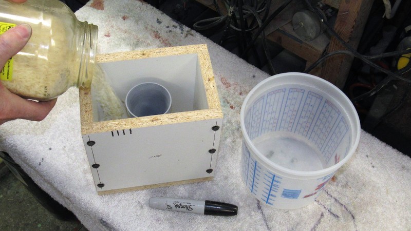
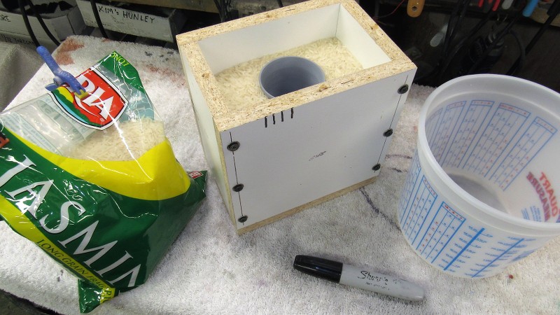
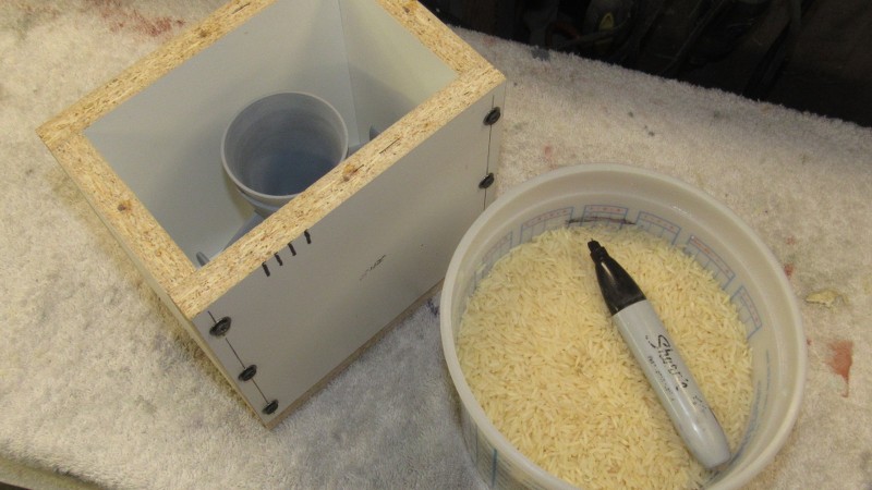
                        I determine the amount of RTV rubber needed for a job by going the 'rice' route: You simply pour rice into the void between master and flask containment till you reach the top or the point where you want the second pour of tool making rubber to start. In this case I want the initial pour of rubber to top off at the mid-point of the masters radial flange.

                        Math?... we need no stink'n math!


                        One of the many advantages of hooking up with an Asian gal is that there is always plenty of rice in the house! (Sheeee... she must never know).


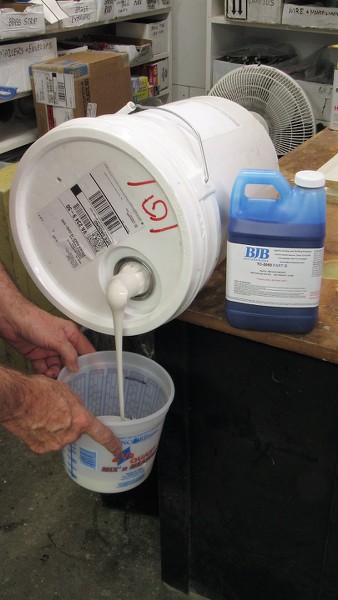
                        It's then a simple matter to pour the rice into the rubber mixing container and mark off the container -- that mark indicates exactly how much tool making rubber you need to mix up. Duh!


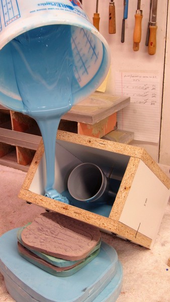
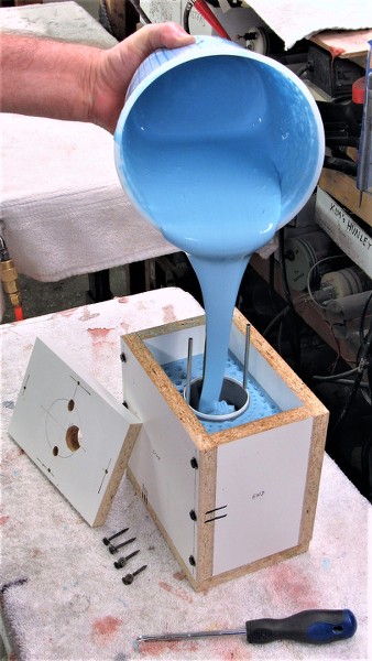
                        I started the tool making rubber pour by severely angling the flask like this to insure that no air-bubbles would be trapped under the concave troughs of the horizontal stabilizer trailing edges. Once those areas were submerged in rubber I positioned the flask upright and finished the pour.


                        No wasted rubber. That stuff is expensive!!


                        Who is John Galt?

                        Comment

                        • SteveNeill
                          Commander
                          • Apr 2020
                          • 315

                          So I learned something new! Damit I thought I knew everything. Well you showed me, literally. Rice! I owe you all the money I'll save on RTV now David. And yes, no stinking math. I thought it was badges but it works. ;)

                          Comment

                          • He Who Shall Not Be Named
                            Moderator
                            • Aug 2008
                            • 12254

                            Originally posted by SteveNeill
                            So I learned something new! Damit I thought I knew everything. Well you showed me, literally. Rice! I owe you all the money I'll save on RTV now David. And yes, no stinking math. I thought it was badges but it works. ;)
                            Over four decades ago I had attended my third, and (as it turned out, last) 'prospective club member' meeting at this over-officious model boat builders club in Hampton; an insufferable collection of stuffy old farts more steeped in tradition and procedural decorum than model building. The club President preferred to be addressed as, 'Captain', and each motion from the Chair was heralded by a ringing of the clubs, 'ships bell'.

                            I **** you not! What a bunch of tight-asses!

                            Amongst all this pretentious horse-****, there was this one guy who put out some real valuable model building tricks, technique, and sound advice. I hung on his every word. The rice trick came from him. And my apologies to him (likely long dead now) for that and his overall attitude of helping anyone, no matter how low on the social totem-pole they were regarded by the other pipe-smoking, diner jacket wearing, fashion monkeys. That one guy was a fount of knowledge in a sea of sticky molasses. He was the only reason I came back after my first trial club attendance.

                            See, even the most obnoxious goats-ass will reveal the occasional diamond. You just have to sometimes put up with the stink to walk away with something worthwhile.

                            Oh, big surprise, I never made it to the status of 'member' in that oh so august group of eclectics, and oh so prim and proper Gentlemen! They just could not get my round peg to fit their square hole.

                            **** 'em!
                            Last edited by He Who Shall Not Be Named; 02-03-2021, 11:08 AM.
                            Who is John Galt?

                            Comment

                            • He Who Shall Not Be Named
                              Moderator
                              • Aug 2008
                              • 12254

                              After about twelve-hours under two heat-lamps the block of Silicon Room Temperature Vulcanizing (RTV) rubber had cured hard and I took the flask apart.


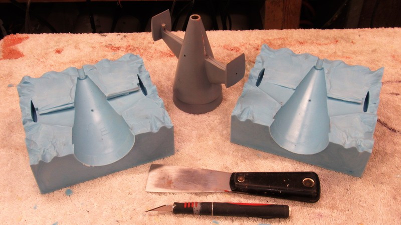
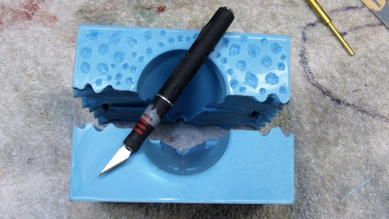
                              I yanked out the brass rods and established centerline verticals on the rubber block to help guide me as I cut the block into two approximately equal halves -- that operation, inevitably sloppy, would produce the keying network that would register the two halves together. More on that horror show shortly.


                              I purposefully avoided straight cuts at the surface of the block of rubber -- the wavy lines would insure an aggressive keying network. But, about a half-inch into the cut I straightened the flange as best I could and worked as carefully as I could to avoid cutting into the master, though some dings (easily filled and sanded smooth later) did occur.


                              Into the top of the block, that world become the flange line of the core piece of the tool, I dug out deep 'dimples' to start the keying network between the core portion of the tool and the two-piece block of rubber beneath.


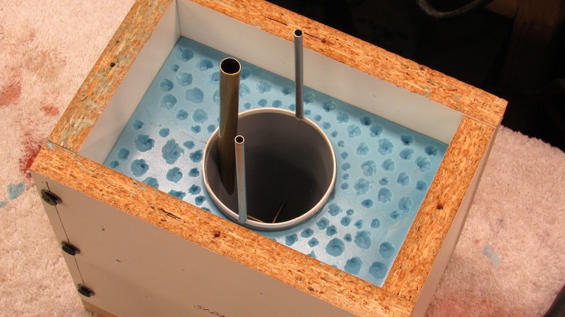
                              The tail-cone master was reinstalled into the two piece 'block' and a riser ring attached to the forward end of its radial flange -- a form of bubble-catcher. Atop the riser are two tubes that will form the vents within the core portion of the too.


                              Pouring the third section of the tool. The large brass pipe will form the sprue.


                              Who is John Galt?

                              Comment

                              • Monahan Steam Models
                                Captain
                                • Apr 2020
                                • 755

                                Precision gift wrapping, only the wrapping keeps on gifting presents!

                                Comment

                                Working...