
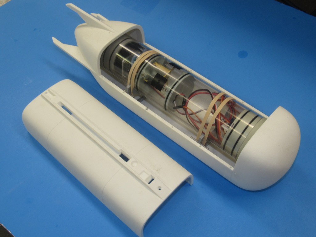
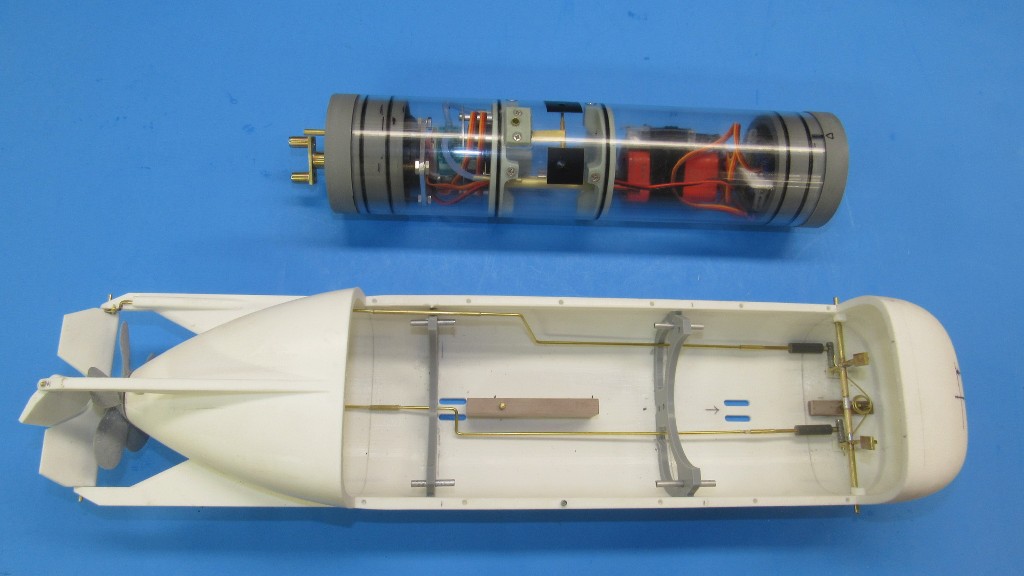
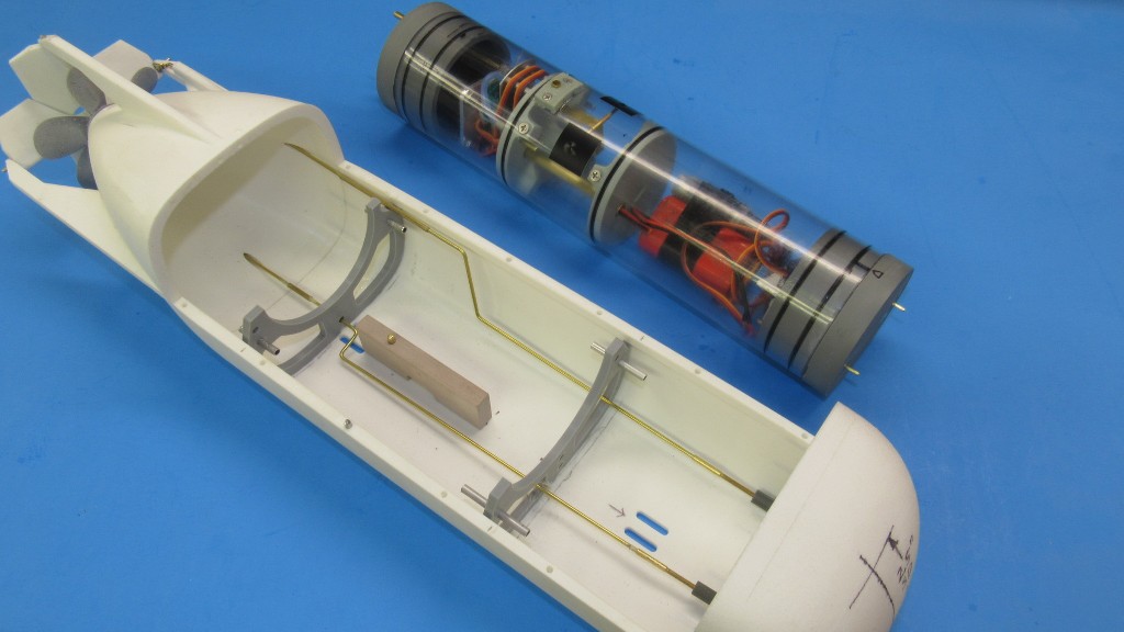
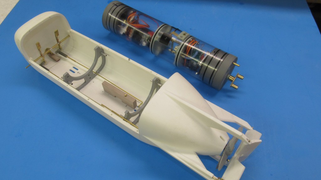
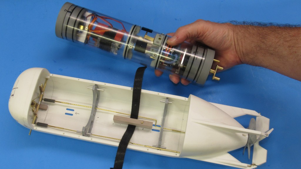
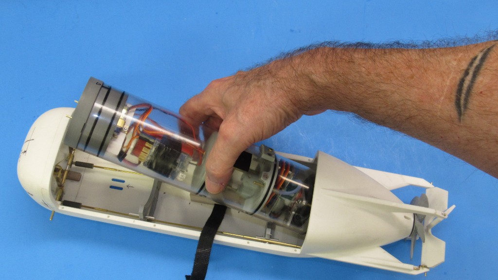
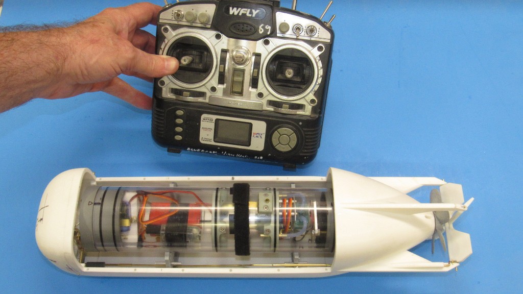
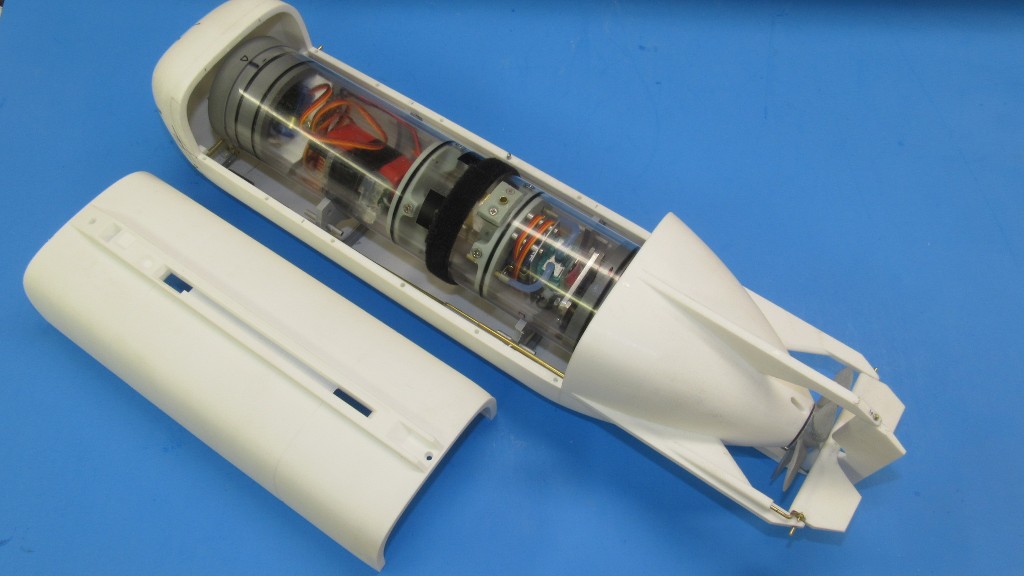
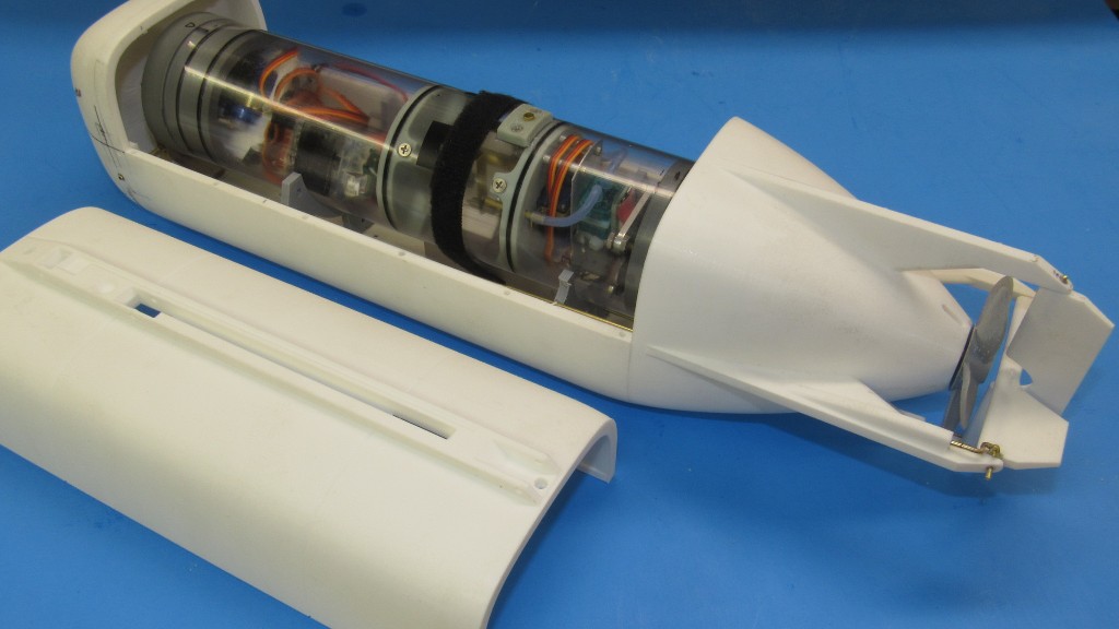
Darrin Hataway's 1/15 scale swimmer delivery vehicle (SDV) r/c model kit came to me as 3D printed parts. The six parts that constitute the hull arrived with the lower hull -- itself comprising three parts -- already assembled; the upper hull separate, but outfitted with indexing pins to assure a tight, secure mating with the lower hull; and two SubDriver foundations. The only other parts to this very simple to assemble kit were the single rudder, single stern planes, propeller, and set of bow planes.
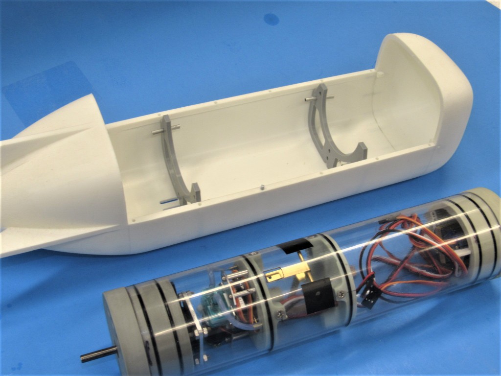
My job was to develop a SubDriver to make the thing go; and to come up with a practical means of spinning the propeller; and getting the control surfaces interfaced with the SD's servos. Once I get the thing into the water I'll make recommendations as to how to improve the 3D files to correct flaws and suggestions as to what it will take to make the eventual product more user-friendly.
This little r/c submarine will be perfect for pools and small bodies of clear water -- environments where a vehicle of tight turning radius, minimal table-space and requiring only basic support equipment. This little SDV model will fill the bill nicely.
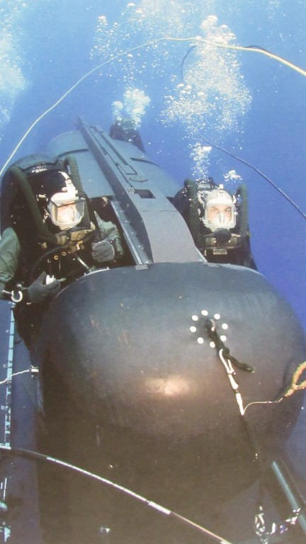
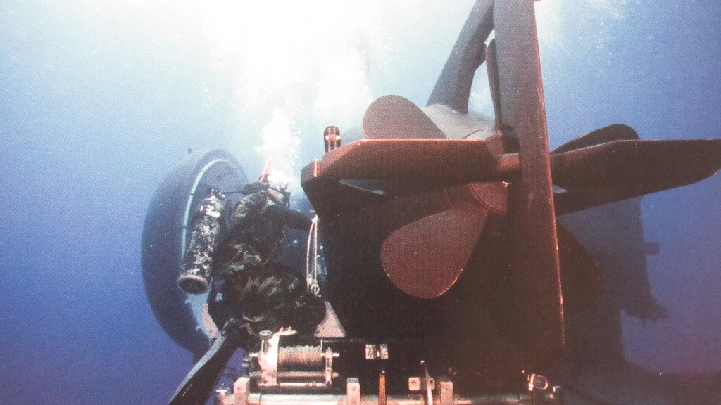
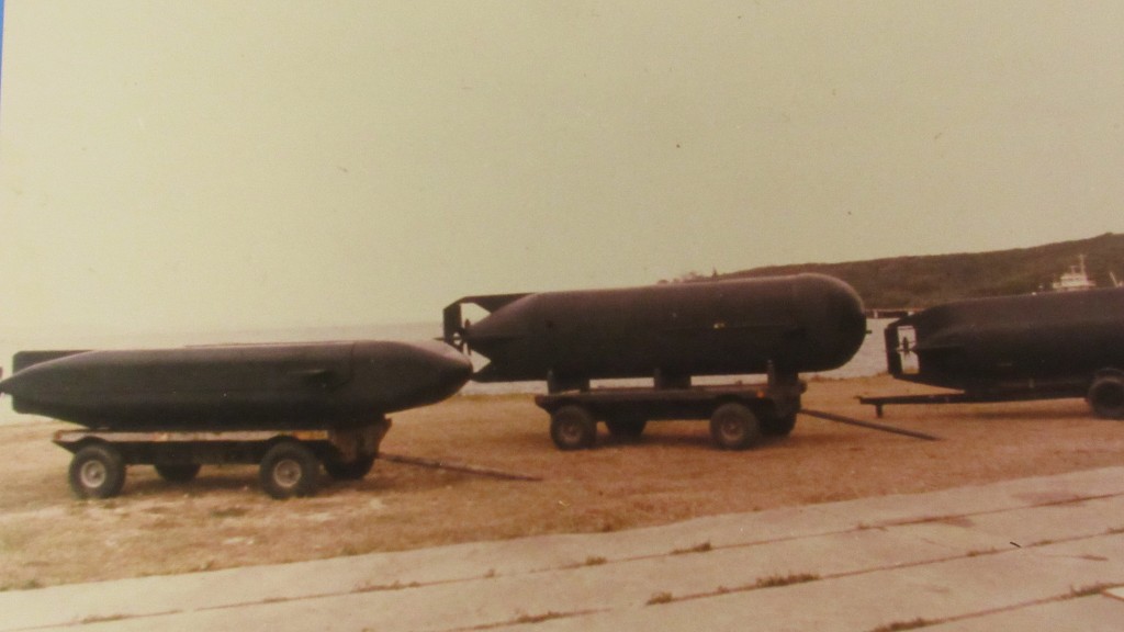
The actual MK-8 SDV's have been in use for decades. These are wet type vehicles that deploy 'operators' to and from the work site. They can be deployed from submarines, surface craft, or from shore. Typically they are housed in special dry-shelters mounted to the deck of a parent submarine -- in operation the parent submarine assumes a shallow depth, hovers, and the SDV -- assisted by support divers -- is removed from its shelter, readied, manned, and sent on its way.
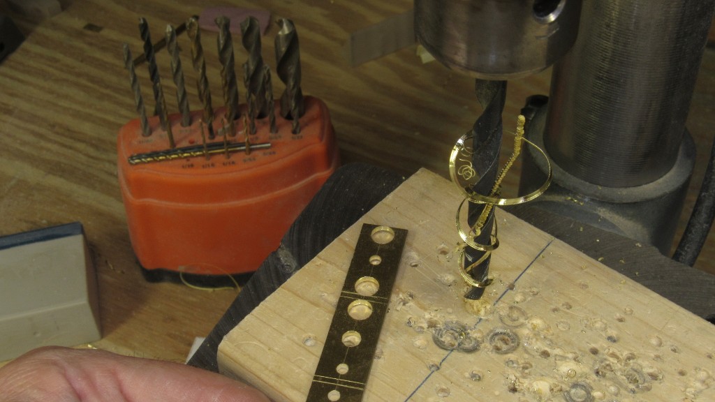
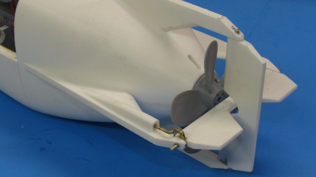
Today's task was to manufacture the pushrods, clevis' and control horns that translate the fore-aft motion of a pushrod into a torque that rotates the rudder and stern planes.
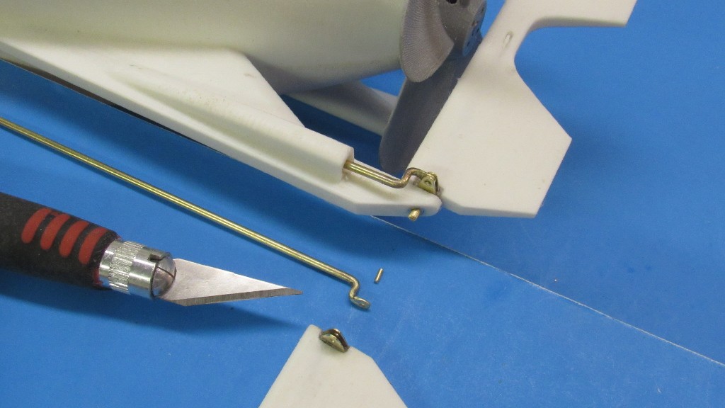
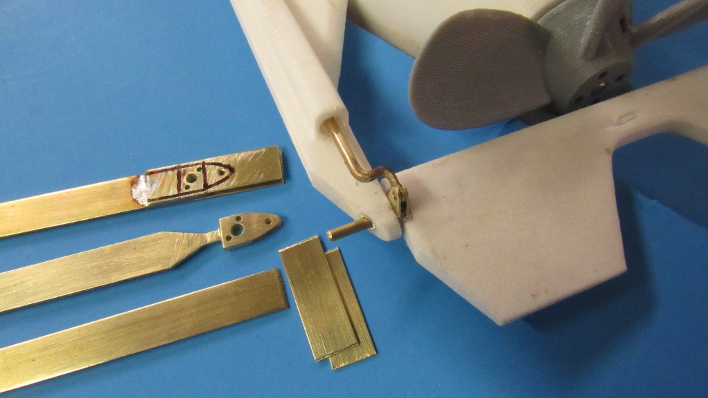
The rudder and stern plane receive a control horn at one end, that horn pined to a pushrod clevis. In actual practice the fore and aft motion of the pushrod swings the control surface by the 'pilot' who sits in the front of the vehicle, in tandem with the 'co-pilot/navigator'. On the model servos move the pushrods through a bell-crank linkage.
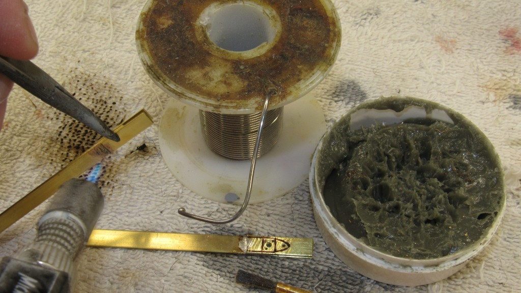
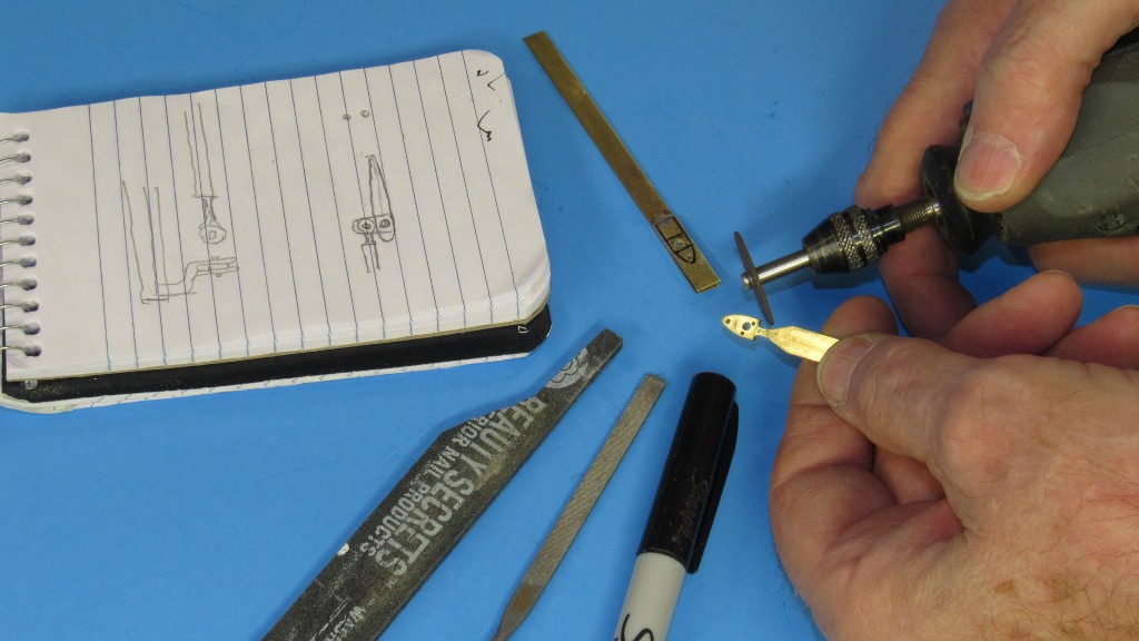
A control horn is simply a soldered sandwich of three pieces of brass strip. The center is .030" thick with the two outer strips .014" thick. Portions of the outboard strips of brass extend past the end of the center strip to form the cavity in which the pushrod clevis is later inserted and pined in place.
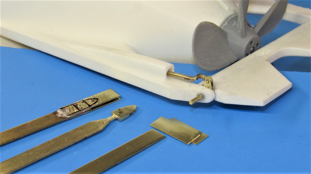
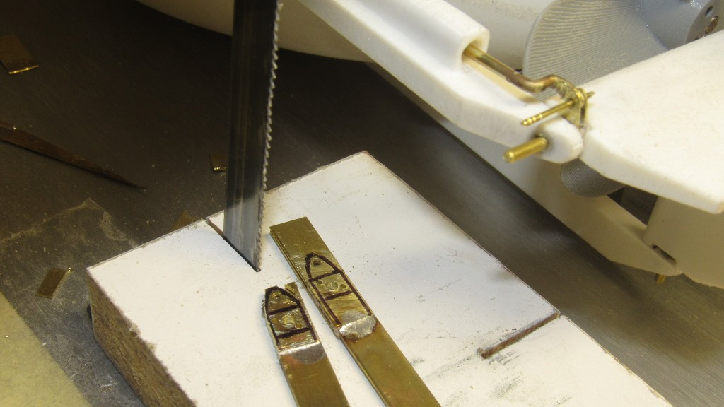
The outline of the horn is inked onto the work and rough-cut to shape on the band saw. From that point on it's hand work with the aid of a rotary tool.
Final shaping is done with rotary cut-off wheel, files, sanding sticks, and steel wool. Holes are drilled to pass the control surface bearing pin and horn brass securing nails.
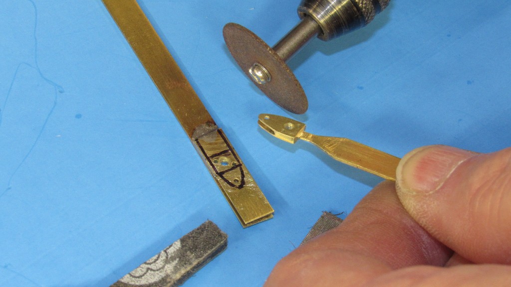
Note that a 'handle' is retained -- the middle length of brass strip -- during shaping of a horn. This makes it much easier to maneuver the work as I hand work it. KISS!
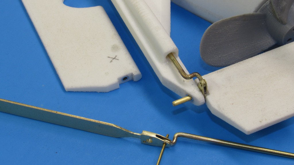
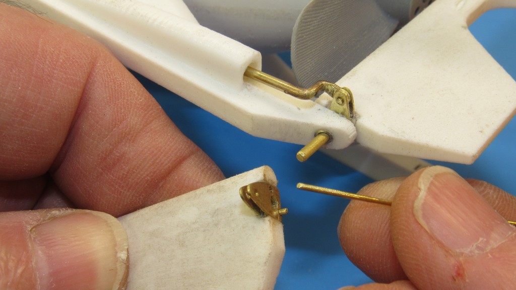
After tack-gluing the brass control horn to the outboard end of a control surface I drill holes into the control surface, and insert .030" diameter brass securing nails, which are first coated with thin formula CA adhesive. This insures a good, sound union between horn and control surface; a union that should survive handling accidents and the torque presented by the pushrod.
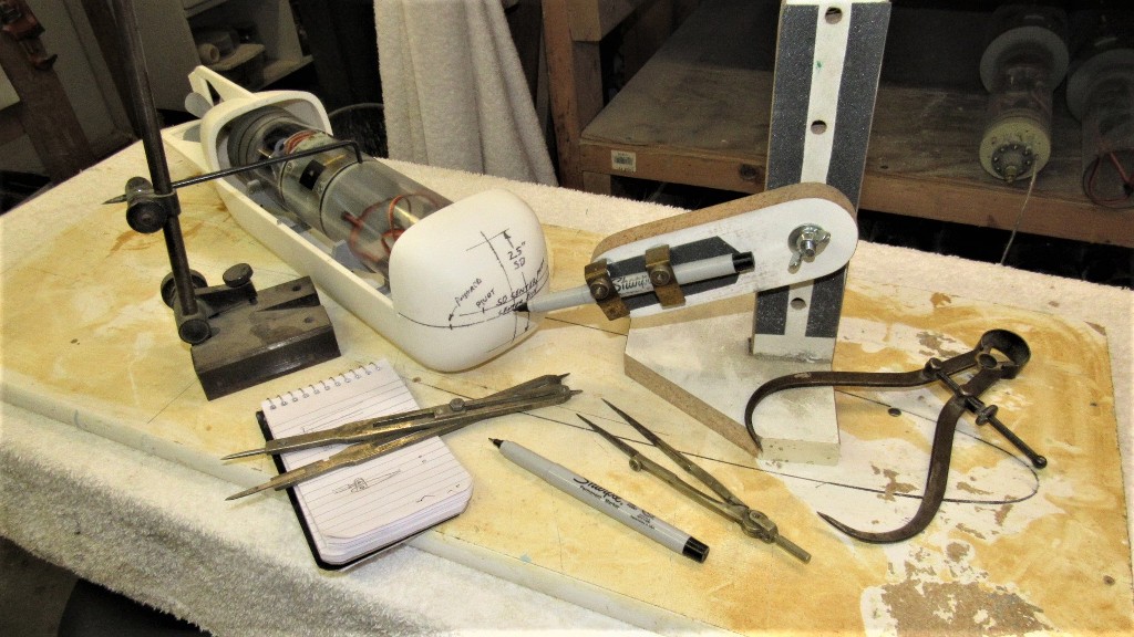
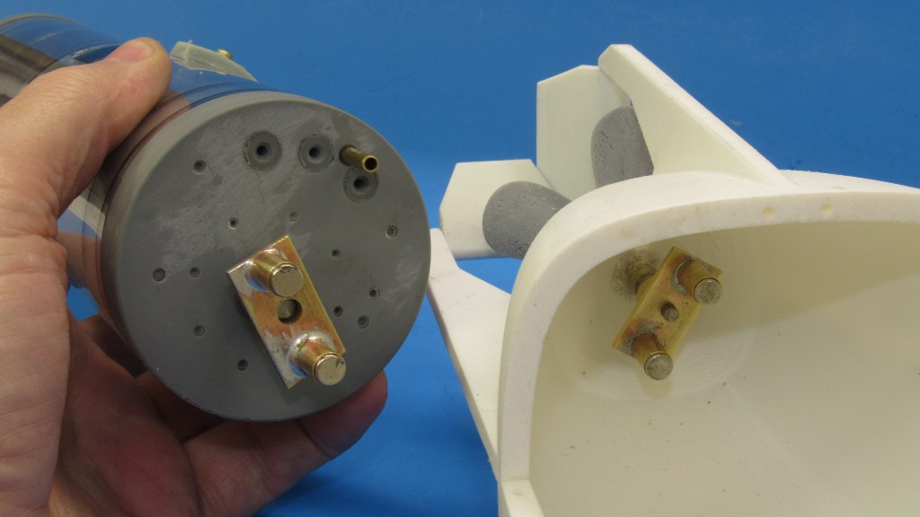
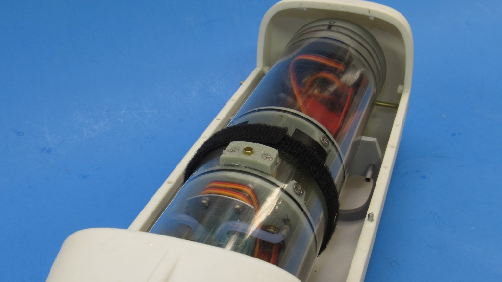
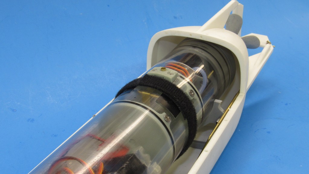
A unique feature of this little r/c submarine is that the two servo outputs are at the front of the SubDriver, not the back. I'll have to device a pair of bell-cranks to translate motion back to the control surface pushrods. Tomorrow's task.
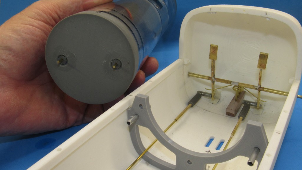
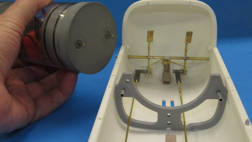
Here I've marked out the location of the pivot rod that will pass through holes in the bow becoming the axil about which the two translating bell-cranks will rotate.

My job was to develop a SubDriver to make the thing go; and to come up with a practical means of spinning the propeller; and getting the control surfaces interfaced with the SD's servos. Once I get the thing into the water I'll make recommendations as to how to improve the 3D files to correct flaws and suggestions as to what it will take to make the eventual product more user-friendly.
This little r/c submarine will be perfect for pools and small bodies of clear water -- environments where a vehicle of tight turning radius, minimal table-space and requiring only basic support equipment. This little SDV model will fill the bill nicely.
The actual MK-8 SDV's have been in use for decades. These are wet type vehicles that deploy 'operators' to and from the work site. They can be deployed from submarines, surface craft, or from shore. Typically they are housed in special dry-shelters mounted to the deck of a parent submarine -- in operation the parent submarine assumes a shallow depth, hovers, and the SDV -- assisted by support divers -- is removed from its shelter, readied, manned, and sent on its way.
Today's task was to manufacture the pushrods, clevis' and control horns that translate the fore-aft motion of a pushrod into a torque that rotates the rudder and stern planes.
The rudder and stern plane receive a control horn at one end, that horn pined to a pushrod clevis. In actual practice the fore and aft motion of the pushrod swings the control surface by the 'pilot' who sits in the front of the vehicle, in tandem with the 'co-pilot/navigator'. On the model servos move the pushrods through a bell-crank linkage.
A control horn is simply a soldered sandwich of three pieces of brass strip. The center is .030" thick with the two outer strips .014" thick. Portions of the outboard strips of brass extend past the end of the center strip to form the cavity in which the pushrod clevis is later inserted and pined in place.
The outline of the horn is inked onto the work and rough-cut to shape on the band saw. From that point on it's hand work with the aid of a rotary tool.
Final shaping is done with rotary cut-off wheel, files, sanding sticks, and steel wool. Holes are drilled to pass the control surface bearing pin and horn brass securing nails.
Note that a 'handle' is retained -- the middle length of brass strip -- during shaping of a horn. This makes it much easier to maneuver the work as I hand work it. KISS!
After tack-gluing the brass control horn to the outboard end of a control surface I drill holes into the control surface, and insert .030" diameter brass securing nails, which are first coated with thin formula CA adhesive. This insures a good, sound union between horn and control surface; a union that should survive handling accidents and the torque presented by the pushrod.
A unique feature of this little r/c submarine is that the two servo outputs are at the front of the SubDriver, not the back. I'll have to device a pair of bell-cranks to translate motion back to the control surface pushrods. Tomorrow's task.
Here I've marked out the location of the pivot rod that will pass through holes in the bow becoming the axil about which the two translating bell-cranks will rotate.


Comment