
I think the wires got crossed. You should aim to keep the esc as close to the battery as you can, matters a lot less if the wires to the motor are longer.
-
-
Good catch, Andy! You were clear, I read your comment wrong.
So, that puts the battery, two servos, the BEC, and the ESC up forward. That's a lot of wires, in close proximity to one another, through a very tight conduit (three motors wires, two servo leads, power zip-cord, BEC output wires, and ESC lead).
Yikes!
I so much want to keep the ESC and BEC in the after dry space! That would mean a battery-to-ESC cable about 15" long. Can I get away with that, Andy?
DavidWho is John Galt?Comment
-
I would give a cautious, probably. The best people to consult about this would be Mtroniks. They might say fine, or possibly advise fitting an additional low esr cap across the leads.Comment
-
The RC truck/car folks use a cap pack to deal with that.
I am just beginning to play with brushless motors. So, this conversation is very relevant. Here is a YouTube on this topic of a capacitor on an ESC.
Here is a video on some basics about a cap pack. Now with one you can leave your ESC with the motor.
or make your own
Last edited by trout; 01-08-2020, 11:55 AM.If you can cut, drill, saw, hit things and swear a lot, you're well on the way to building a working model sub.Comment
-
Model cars and trucks present probably the severest loads for esc's, as they're constantly slamming on the brakes and have widely varying loads on the motor when compared with aeroplanes and boats.Comment
-
Hello David,
I have machined up some renshape endcaps. I am currently thinking about how tight the fit should be for the section ( with the o-rings) that fits inside the tube. Do you machine the diameter such that it is a tight friction fit or do you have a tiny gap / difference with the O- rings making up the difference and providing the press fit.
I suppose another way of asking is how much depth do you create for the O-ring groove? Is the depth of the groove about equal to the radius of the O-ring? As I have mentioned to you, I intend on making my endcaps the way you do. What shrinkage factors if any should I consider? Would there be any with the urethane moulds. I haven’t encountered it with my appendage parts moulds...yet.
I hope this makes sense..
David HComment
-
Andy has some excellent videos on YouTube about how to size endcaps and Orings. Well worth a watch I will see if I can get a link.
Peter
https://youtu.be/hWcryehE7EU this is part 2 of 3....couldn't find part 1 but as mentioned an excellent watch. (pretty sure 1 is on there somewhere)Last edited by Peter W; 01-10-2020, 12:34 PM.Comment
-
Part 1 - https://www.youtube.com/watch?v=wixmu3MPhjo
Part 2 - https://www.youtube.com/watch?v=hWcryehE7EU
Part 3 - https://www.youtube.com/watch?v=lh5kNb7m_oQ
Very fine work by Andy! Wish he would do more (nudge, nudge).If you can cut, drill, saw, hit things and swear a lot, you're well on the way to building a working model sub.Comment
-
I machine my endcaps from sheet stock plastic (PVC, polycarbonate and acrylic/pmma all work well), or use aluminium for bayonet rings. I rarely make more than one of anything, so there is little logic in casting unless I need extra features within the endcap.
However if I went this route I wouldn't cast a groove into endcaps. I would just make a simple blank without the groove, and machine that in later, also leave enough meat on the part to allow for inconsistencies in the inside tube diameter- which can vary greatly,-and machine the part down to fit. With regards to groove depth I tend to work between 10-15% of o-ring cross section, depending on how accurate the tube is. Technical literature will often specify up to 25% squish, well I personally find that is too much and you'll have a fine time trying to remove your caps. Bear in mind that o-rings can be used in systems running hundreds of pounds of pressure, whereas we might be dealing with half an atmosphere at most.
I tend to use 3mm (1/8") o-rings for most cylinders, but for sizes below say 50mm (2") I drop down to 2mm or less. I use nitrile and silicone o-rings, the latter tend to be a little bit softer, and don't degrade in the sunshine. I find nitrile works just fine, it's stronger and is a bit cheaper. Avoid exotics like Viton, EPDM etc. Overkill and much more expensive.
One thing worth noting, if you have the room to do it, making the outer edge of endcap a bit bigger than the cylinder diameter will provide a nice piece to grip when removing the cap. Adding a knurled finish on the same edge will further improve grip. I'd also keep the edge as thick as possible, as PU resin tends to be quite brittle unless reinforced with glass or carbon fibre. All quite easy to integrate into a rubber tool.Comment
-
Hello HWSNBN Sir
Would you tell me from whom do you get your gears that you used with your brushed motors to make a Dual Drive System for the Revel Type 7 & 9 and the part numbers Sir.
ThanksComment
-
Thanks everyone,
I did’nt know about those videos. Very good. I have made plenty of cylinders before and machined numerous endcaps. I just wasn’t sure about whether I needed to consider shrinkage of the polyurethane at all. I am casting these endcaps because I want to go into limited production to produce a cylinder that will integrate into my kits.
Thanks once again.
David H
Zero Bubble model design.Comment
-
Polyurethane resin typically has very low shrinkage, unlike polyester resins which have very high shrinkage. I would estimate no more than 1-5% depending on thickness, cure time, and whether you add any filler in the resin e.g. glass, carbon fibre etc.Comment
-
You cast your bulkhead radial flange over-size to the biggest diameter stock you can find (a stated diameter is one thing, the tolerance the manufacturer employs is another). And you don't cut it down to size and incorporate the O-ring grooves till you identify the specific cylinder the bulkhead is going into.
No getting around this, Lexan cylinder tolerances are so wide you just can't simply cast a one-size-fits-all complete bulkhead. Each bulkhead has to be lathe turned to fit.
DavidWho is John Galt?Comment
-
Flu! For three weeks! I’m almost over it. However, in those few moments when I could drag my fat ass into the shop I was able to piddle away on three 1/96 scale submarine models representing ‘modern’ types. When completed and made operational they will, this October, join the rest of my sub fleet at this year’s big Fleet-Run event; a wonderful three days of constant scale (1/96 and 1/100 only) ship and submarine running at the City Lake, Rocky Mount, North Carolina.
The smallest of the three, next to the wall, is the USS ALBACORE, that model representing the ground-breaking non-combatant research submarine that investigated the virtues of the tear-drop shaped hull, various control surface arrangements, propeller and battery types, as well as the systems slatted for use in the next generation of attack and missile submarines. Middle, is a model representing a unit of the SKIPJACK class attack submarine, the first American submarines to capitalize on the ALBACORE findings. The model will be completed as the ill fated USS SCORPION. And foreground a model of a Soviet ALFA class. These were the fastest attack submarines ever made and were marvels of engineering and innovation.
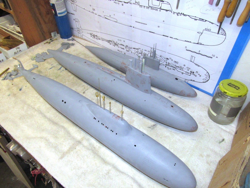
The ALBACORE is assembled from a GRP, resin, and metal kit produced by Scott Terrey and myself; the SKIPJACK is assembled from a GRP, resin, and metal kit I produced back in the 80’s; and the ALFA GRP hull was purchased from The Scale Shipyard (an excellent GRP lay-up, by the way), and I produced all the masters, tools, and parts for the appendages.
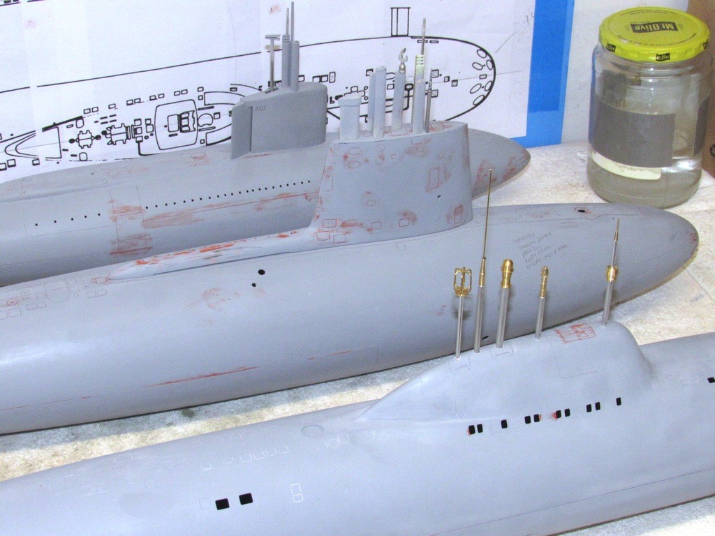
These type subjects present few challenges to the model-builder other than the few deck fittings and their sail mounted retractable optical, air induction and electronic masts. So, that’s where a lot of my scratch-building skills are lavished, as demonstrated in this shot of the masts projecting from the tops of the ALBACORE, SCORPION, and ALFA models.
I’ve been working these three, off-and-on, the past two years, with a plan to get them to the stage where I could address them all, as a group, when it came time to paint, detail, mark, weather, and clear-coat.
It’s a good practice to pace your work sessions on a model – space out your flurry of tasks with a ‘cooling-off’ period. As it’s during those periods of rest that your mind fills with ever more objective thoughts of what-I-did-right-and-what-I-did-wrong, which often leads into a plan to undo or alter recently completed work. Such was the case with the little 1/96 ALBACORE model when I rejoined that project recently.
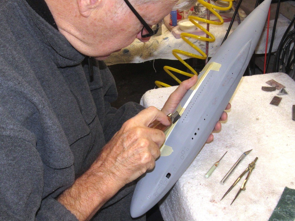
Initially I scribed in a longitudinally running line along each side of the hull. The trouble was instead of a line of slight, graceful curvature; it wound up being a little ‘wavy’ at points along its length. It was during the most recent hiatus (actually, sitting on the toilet … is there a linkage between anus and brain?) that I formulated a method of straightening that engraved line. As it turned out a simple solution in practice, but something that took me several weeks of casual thinking as I pondered how I was going to execute that fix. And it was so easy: tape down a piece of styrene sheet to the hull and re-scribe those portions of the engraved line that were out of true. The task took only minutes. A little touch-up putty over the ‘fixed’ areas of the engraved line, one final pass of the engraving tool, and the two engraved lines were straight and true.
Problem identification plus time and thought, stir in experience, mix well, and you eventually get the best solution to the problem.
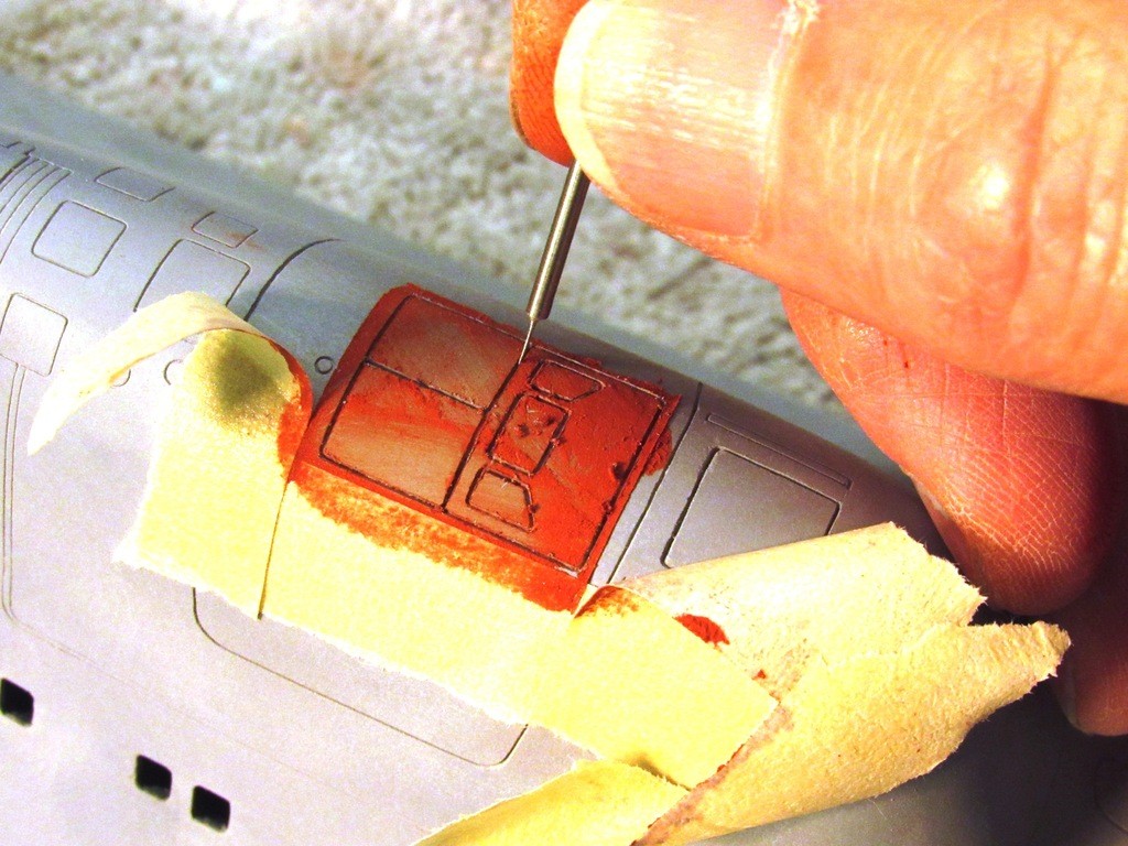
The three models were pulled off the wall and surveyed for sloppy engraving, scratches and tool-marks that required touch-up putty and sanding. Case in point is the ALFA’s bridge closures, represented by these engravings: their outlines were too deep and wide.
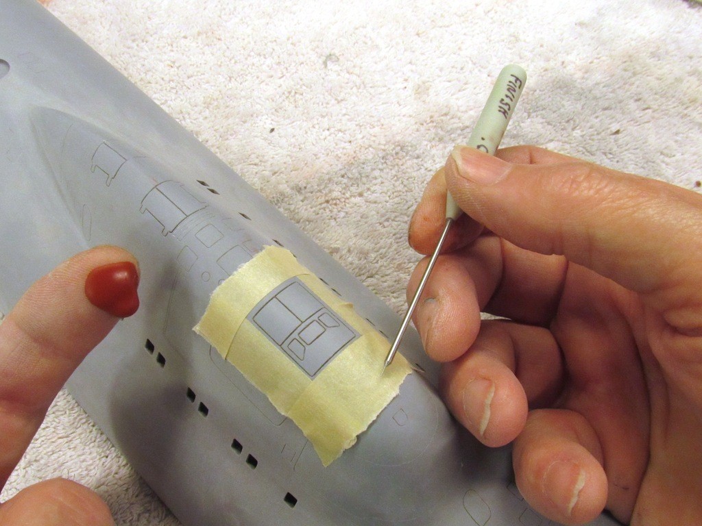
So, I filled the engravings with putty, and while it was still wet I chased out the excess putty with a very narrow scribing tool. Note the use of masking tape to limit the spread of the putty to only those areas needing repair work.
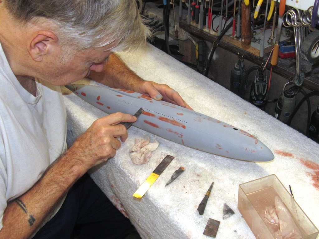
Again, working the three boats at the same sitting, I wet-sanded back applied touch-up putty. Each boat was wiped down with a damp cloth and blow-dried with low pressure air. All scribed lines were lightly engraved to remove any sanding dust. Stiff sanding tools were made by taking a strip of .032” thick brass sheet and CA’ing a piece of #400 grit sandpaper to ones side, and #600 grit sandpaper to the other. These are perfect little sanding blocks for knocking down dried putty. I used tightly wound sandpaper twists to abrade into and over tight compound curves such as the ALFA condenser scoop intakes and stabilizer fillets.
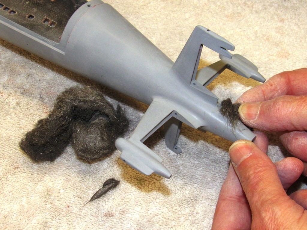
Fine steel-wool is used to lightly abrade tight-radius areas of the model, such as the fillets between ALFA stabilizers and hull. Before using steel-wool on a models surface the steel-wool has to be rinsed in lacquer thinner to remove the preservation oils that impregnate it – that oil there to keep the fine steel fibers from rusting. Failure to degrease the steel-wool can result in poor coating adhesion.
Once all touch-up putty had been applied, sanded smooth, and engraved lines chased out with a scribe, the three hulls and they’re appendages were given spot-coats of primer on the worked areas.
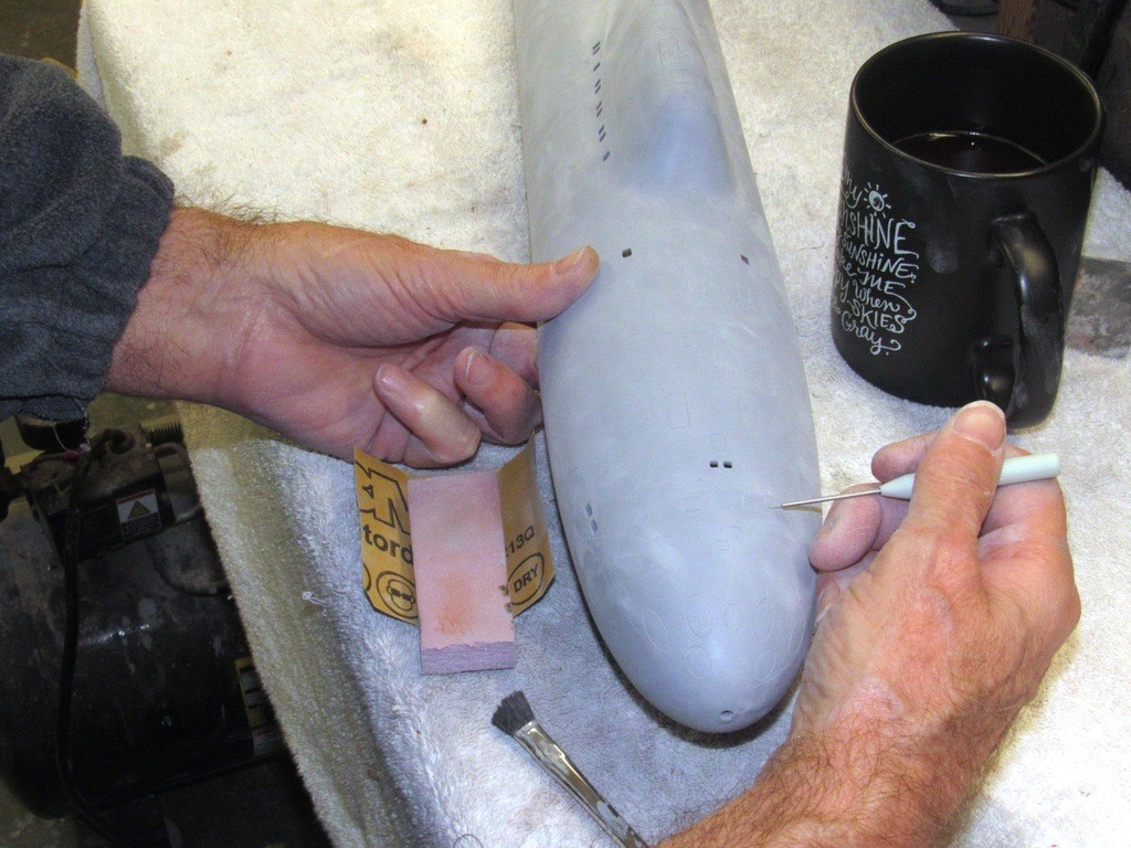
The demarcation lines between stabilizer and hull fillets had to be enhanced after all that sanding and abrasion with steel-wool. So, to re-enhance the fillet plates, I masked the stabilizers and hull with adhesive tape and spray painted on two heavy coats of primer. Removing the mask revealed the desired raised edge of the fillet plates that fair the stabilizers to the hull.
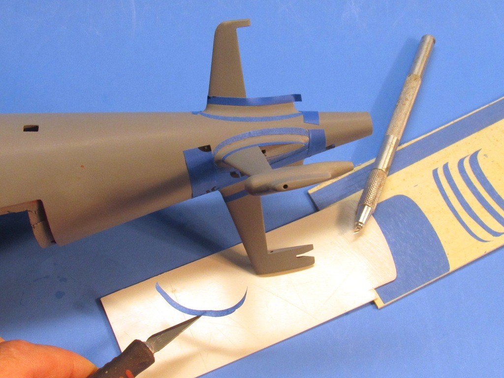
Note the use of s ‘swivel-knife’ and plastic sheet stencil used to produce the uniquely shaped self-adhesive masks.
Who is John Galt?Comment


Comment