Welcome to our forums. For the best in R/C submarine kits, components and accessories, be sure to visit the Nautilus Drydocks
If this is your first visit, be sure to
check out the FAQ by clicking the
link above. You may have to register
before you can post: click the register link above to proceed. To start viewing messages,
select the forum that you want to visit from the selection below.
It takes a great deal of time to produce a new product. The process involves thought, drawings, revisions, masters, production tools, jigs, fixtures, dies, templates, identification of reliable sources of supply, and a rational production methodology. All the things required to get a good product out of one’s head and into a customer’s hands.
I’ve been posting a lot of imagery to this forum without any supporting narrative for several weeks now. No, I have not lost my voice – I’ve simply been terribly busy getting a new product on line – and have had little time to put words to pictures. However, last week I transitioned from development to production and once again have the opportunity to answer questions I’m sure some of the many un-captioned pictures have raised. So, with the completion of the first production run of Modular SubDrivers (MSD) done, and the fabrication process now streamlined, I’ll do my best to get you up to speed on what the MSD system is and how it works.
It’s time for some clarity.
What the hell is a, modular SubDriver? The MSD is a system that propels, controls, and manages the variable ballast water used to place the r/c model submarine in either the surfaced or submerged condition. The MSD is the ‘dry’ element of the otherwise free-flooding model submarine.
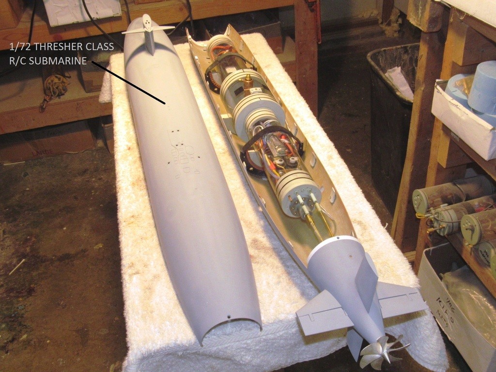
As illustrated below, the scale model submarine itself is nothing more than a free-flooding fairing in which the MSD resides. But, as a true representation of a prototype, the model submarine hull also supports the control surfaces required to dynamically guide the submarine through the water when in motion, and mounts the propulsor that converts motor torque to axial thrust. Better to think of the ‘model’ submarine as, The Real Thing -- which is very much what it is: a practical, guided, underwater vehicle able to alter its weight to either sail along the surface or operate completely submerged where the opposing forces of gravity and buoyancy cancel one another out resulting in the condition of, neutral buoyancy.
I did not invent the concept of a removable water tight cylinder, the category in which the MSD resides. The WTC seems to have originated in Europe better than a half-century ago. No. I’m just the guy who popularized the concept in America and refined it to what it is today, a system now sold under the trade-name of SubDriver.
The recent improvement to the system was to transition from a single length of Lexan cylinder with internal bulkheads separating the three compartments – forward dry space for the battery; ballast tank; and after dry space for the r/c gear, servos, specialized control devices, and propulsion items – through the use of plug-in type unions between three separate lengths of Lexan cylinder. The unions not only eliminate the mechanical fasteners passing through holes drilled into the cylinder; they also offer the ability to employ varied diameters and lengths of cylinder for the three sections. This makes adapting the system to the specific geometry of the model submarine hull easy; better use of the annular space within.
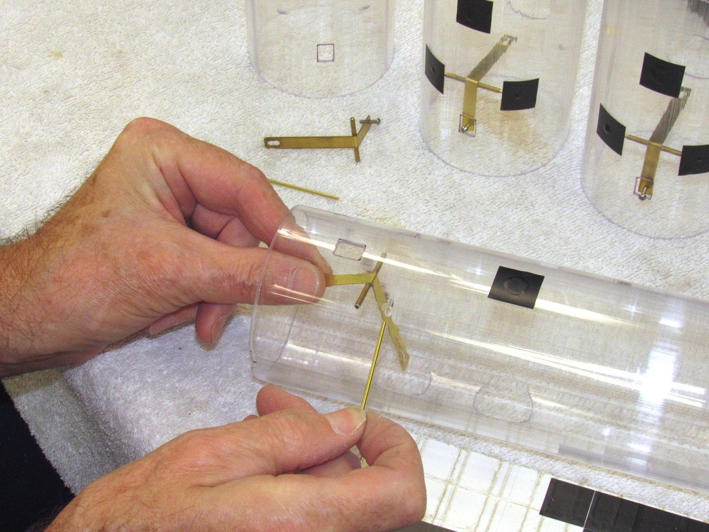
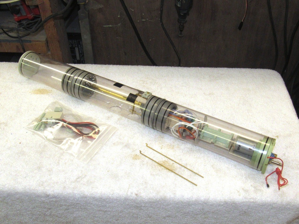
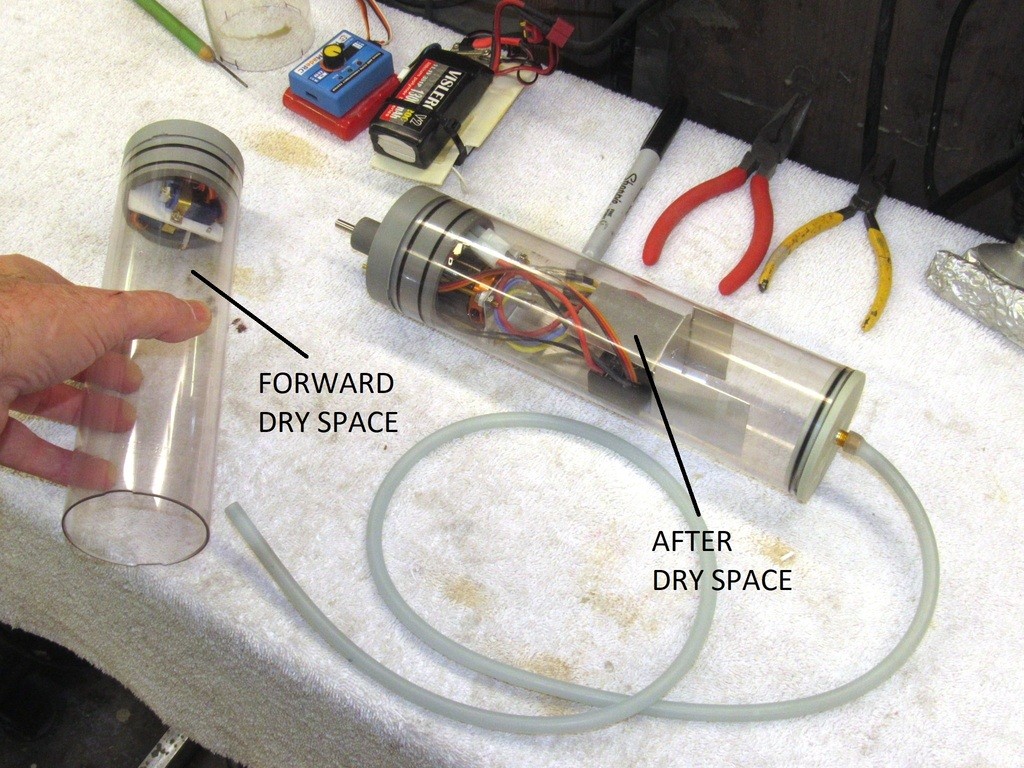
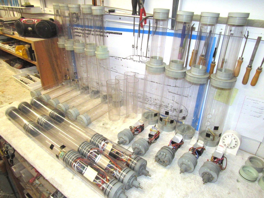
As illustrated here, you see the two smaller diameter dry spaces flanking the central larger diameter ballast tank. The MSD is quickly installed or removed from the model, it being secured with only two Velcro straps. Such accessibility making maintenance, repair, and adjustment easy tasks, and this feature affords the option of employing one MSD to operate an entire fleet of like sized model submarines.
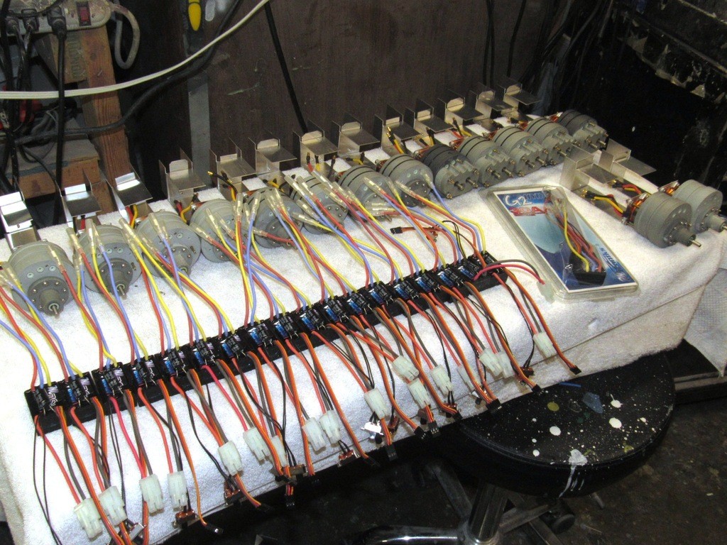
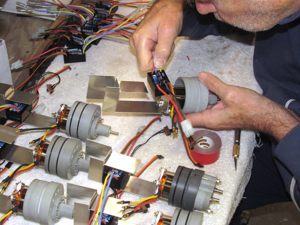
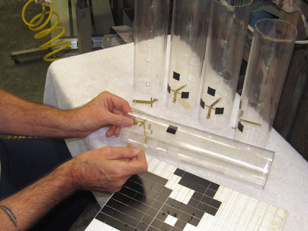
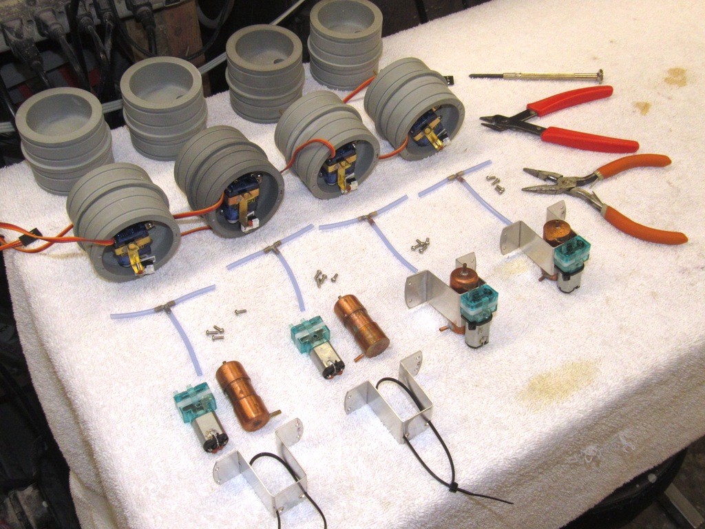
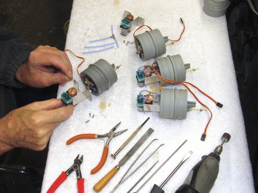
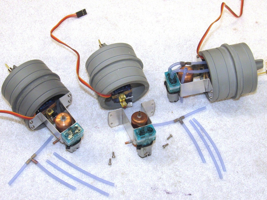
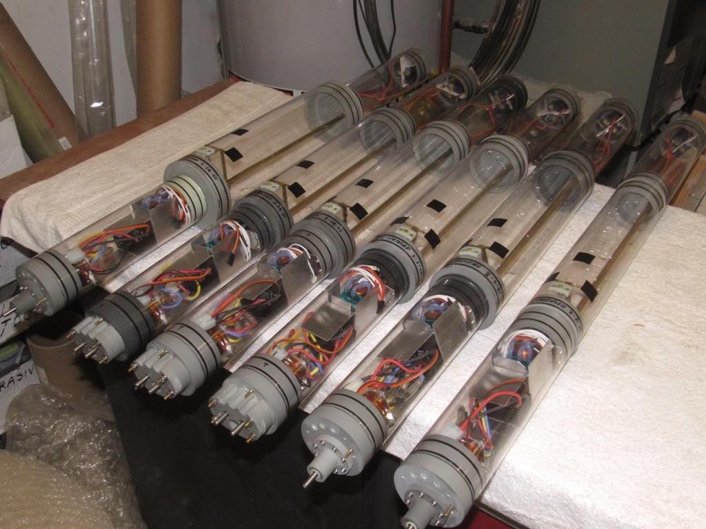
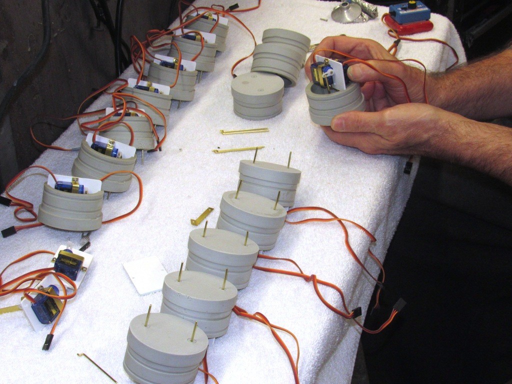
Demonstrating the flexibility of the MSD design are these six units ready for shipment. All feature the same single brushless motor -- though some have only the one output shaft to the propeller, others are equipped with a ‘gear-splitter’ that derives two counter-rotating shafts from the single motor input. Also note the varied diameters of ballast tank. Other than those two variances, all other aspects of these units are identical. A big improvement over the previous SubDriver design is the MSD’s total abandonment of mechanical fasteners to secure internal bulkheads in place. Only friction holds the cylinders onto their respective union radial flanges. Accessing the internals takes only seconds where before it took considerable time and use of tools to remove fasteners and fish out internal bulkheads.
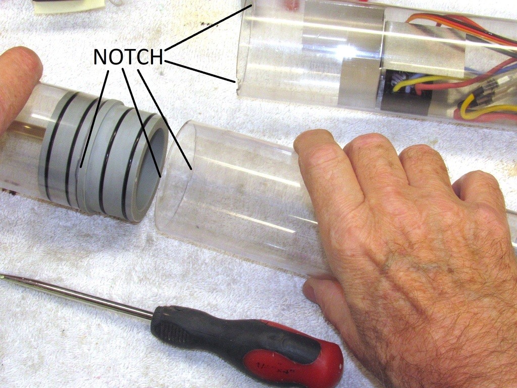
All cylinder sections are retained via the friction between union radial flange O-rings and inside wall of the cylinder. Not to worry, this seemingly fragile attachment is practical because the air pressure within the cylinders never exceeds that of the ambient surroundings. Also contributing to the grip between union and cylinder is that once set, the silicon grease used to lubricate the parts to ease assembly, once set, acts like a mild adhesive making for a most tenacious attachment!
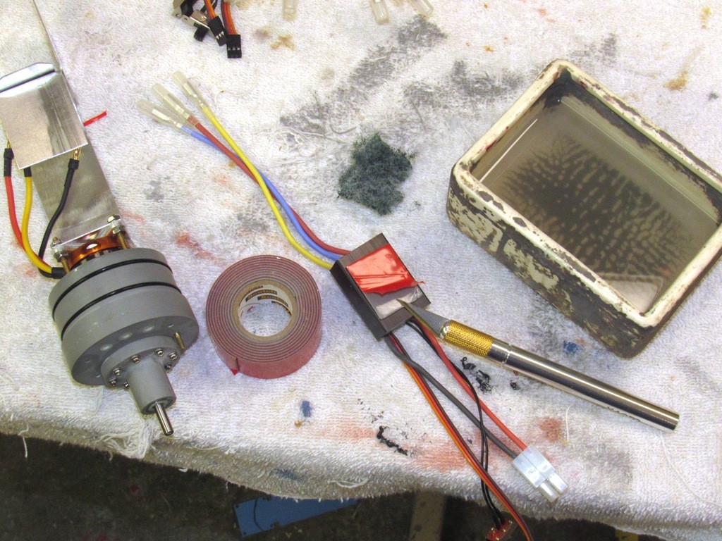
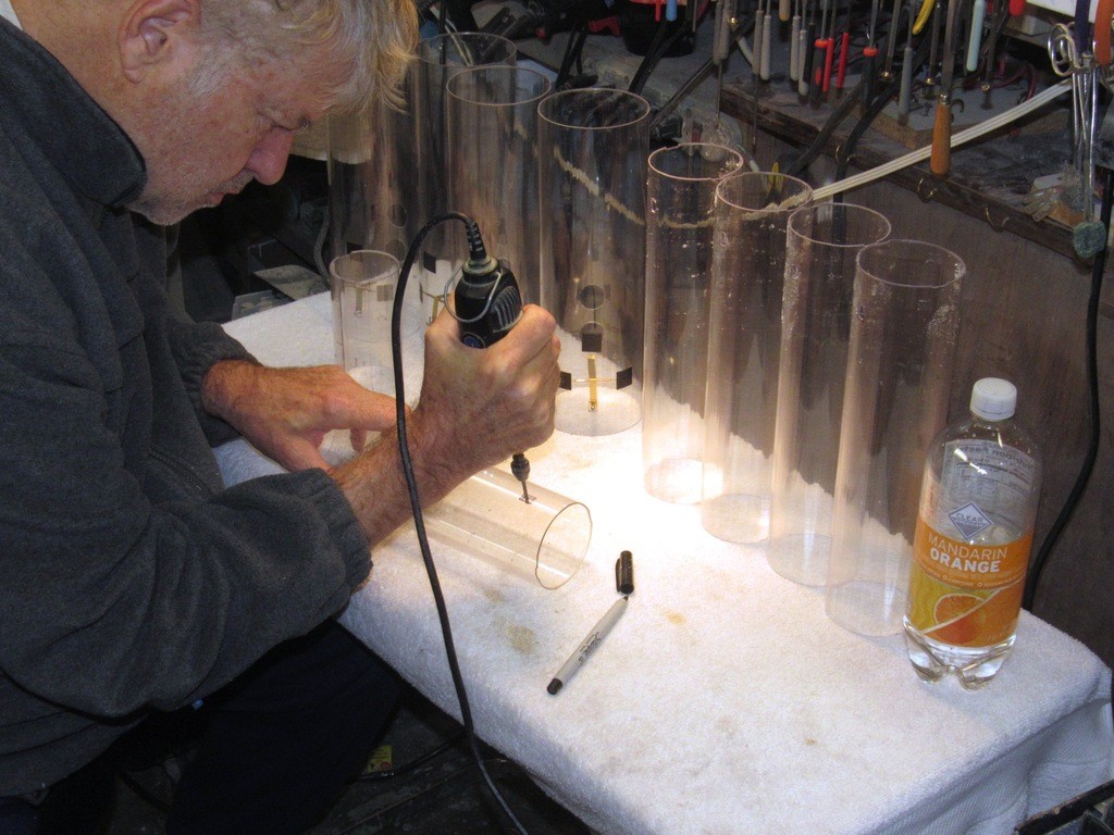
To facilitate removal of a cylinder from its union I’ve provided at the end of each cylinder section ‘notches’ through which the blade of a screw-driver can be inserted and used to pry and easily break the grip between union O-rings and cylinder.
Elimination of mechanical fasteners has eased cylinder fabrication and eliminated the risk of screw holes fracturing and propagating cracks over O-ring seals -- a situation that jeopardizes the systems water tight integrity. No more of that. Now, only the ballasts tank cylinder is machined with holes in it, and as that cylinder never sees any meaningful differential pressure, and is isolated by the forward and after ballast unions, it will never present a flooding path to the dry spaces.
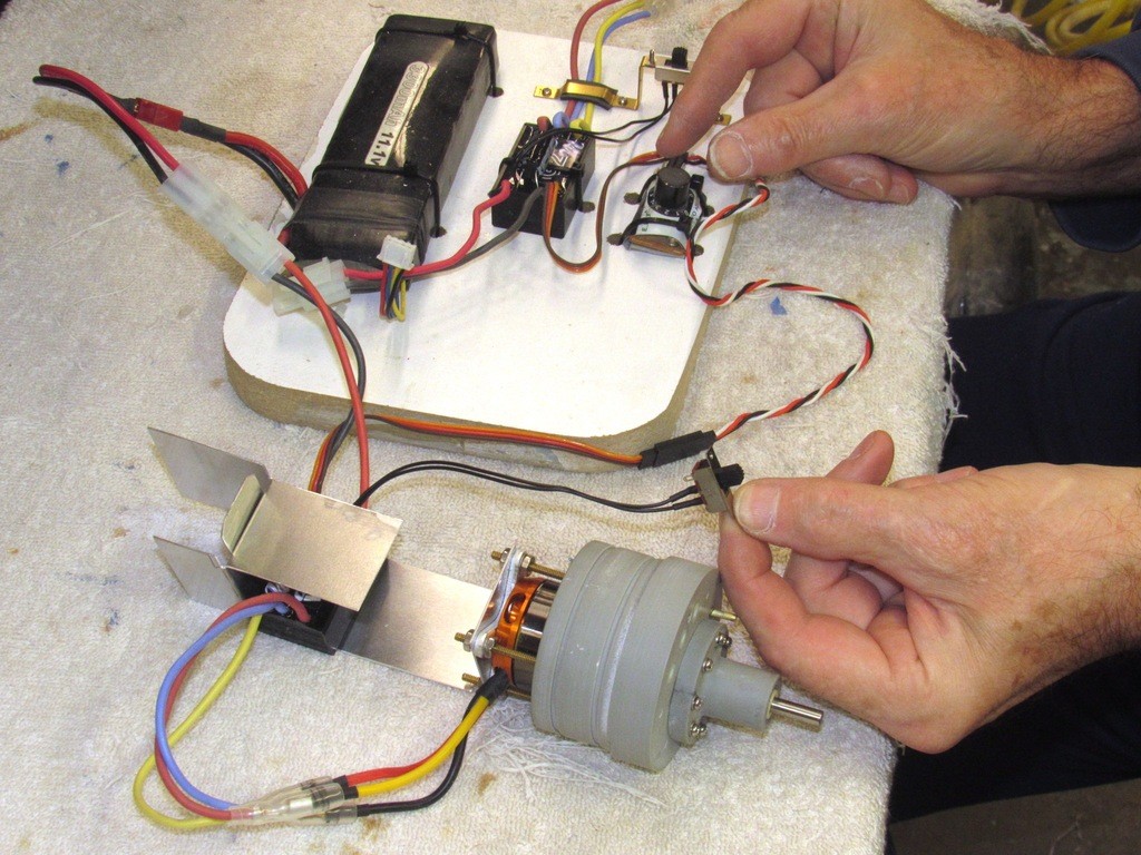
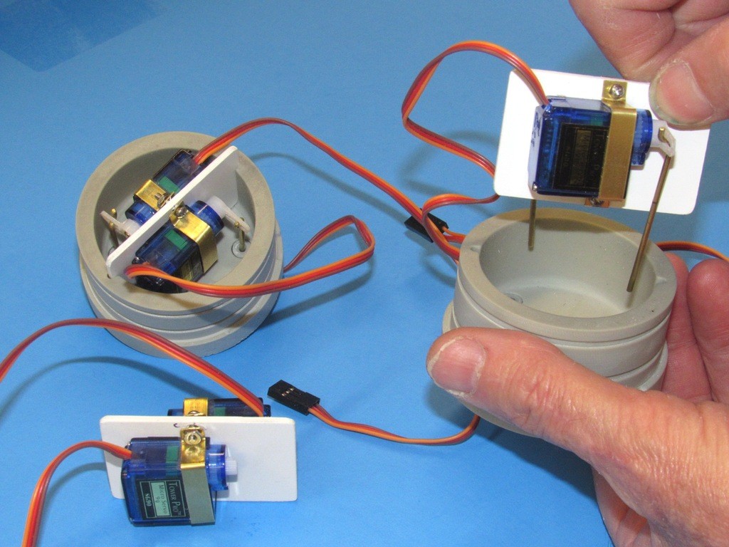
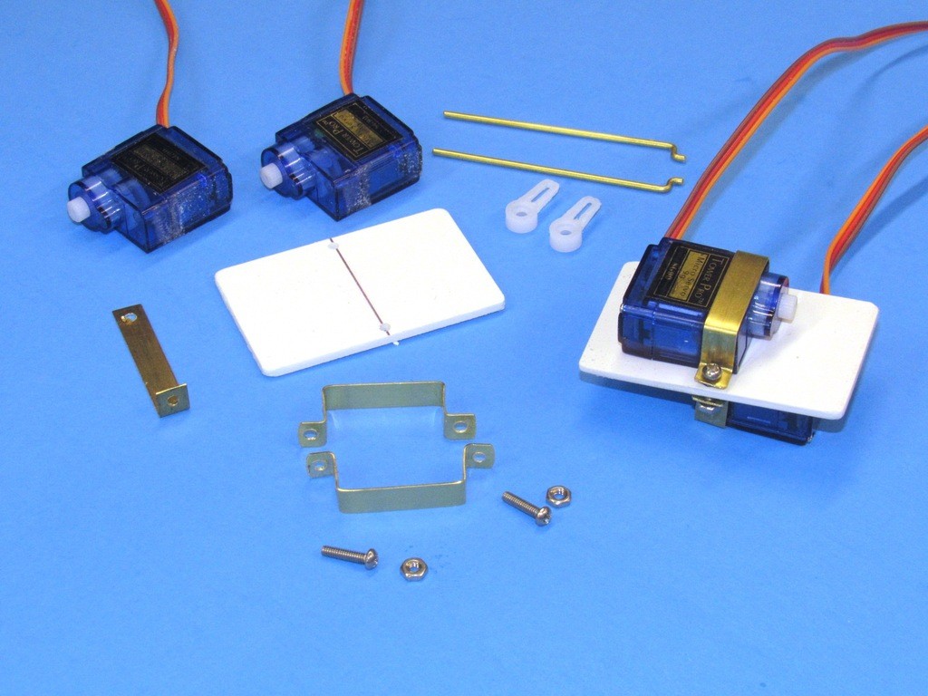
In my hand is the forward dry space cylinder. The forward bulkhead contains two servos. It’s up to the customer on how they are used. Options include operation of bow/sail planes, torpedo launch mechanism, anchor; anything in the forward area of the model submarine that would require a mechanical actuator.
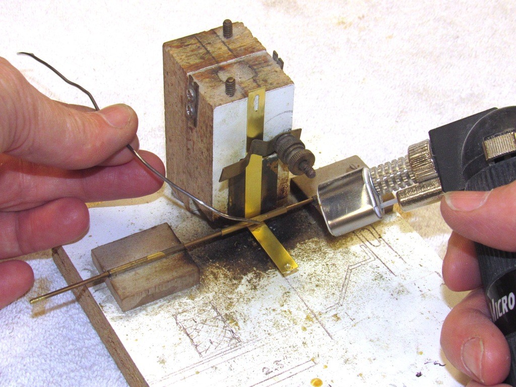
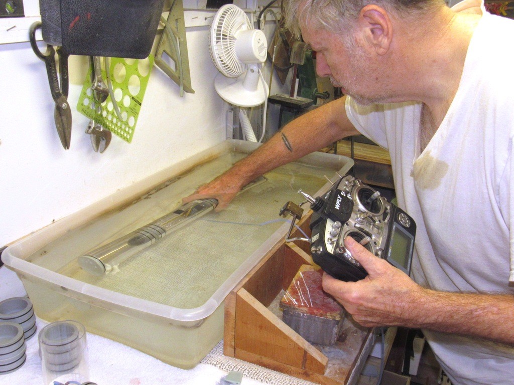
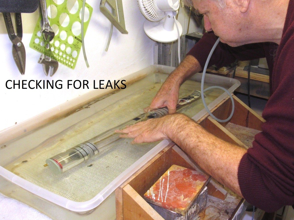
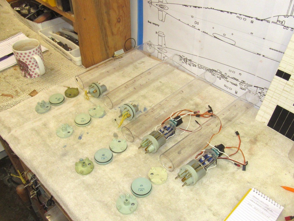
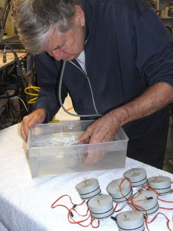
On the table is the after dry space with attached motor bulkhead. A test cap has been installed. A flexible hose making up to the test cap permits me to blow some air into it, slightly pressurizing the space as I dunk it in the test tank and look for escaping bubbles. This is how I perform the initial leak test on all components that must possess water tight integrity.
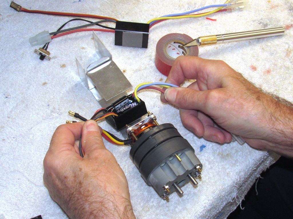
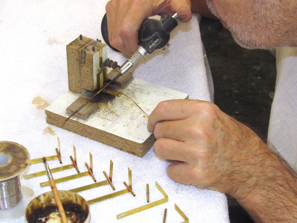
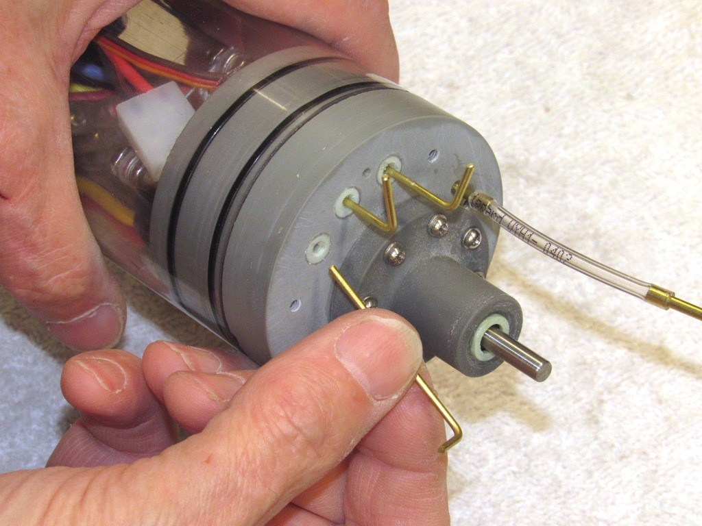
Here I’m preparing a motor bulkhead for its leak test by inserting blanking rods through the three open pushrod seals. The antenna nipple is also blanked off with a short length of flexible tubing capped with a piece of rod.
Typical points of leaks on this item is typically around the O-ring seal at the base flange of the drive-shaft seal foundation, the drive-shaft seal itself, around the three pushrod seal bodies, and the two O-rings between the motor bulkheads radial flange and Lexan cylinder.
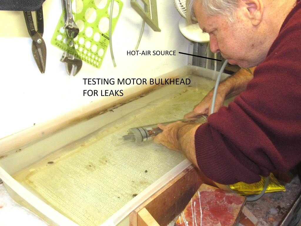
The leak testing itself is a simple affair: blow air into the cylinder, dunk the unit underwater, and look for bubbles. Typical fixes include packing in more silicon RTV sealant around pushrod seal bodies, tightening the shaft seal flange fasteners, or replacing the radial flange O-rings with O-rings of slightly bigger diameter. Yes, this test presents a differential pressure in the wrong direction, but is most useful in finding gross leaks. However, careful production work results in most units passing the gross and later certification leak tests without incident.
Though all servos are tested prior to integration into the forward bulkhead, they do get a lot of handling as they are mounted upon their foundation and their pushrods made up to the pushrod seals. So, as a precaution, I test the servos for correct operation, and non-binding of the linkages, after assembly.
In addition to the leak-test, the ballast section of the MSD is subjected to a ‘certification’ process. This is a test of the ballast sub-systems ability to flood and blow ballast water in and out of the tank, and to do so by either taking external air from atmosphere, through the snorkel on or near the surface; or to draw a suction from the limited amount of air within the two dry spaces of the system, which would be the case when the snorkel is submerged.
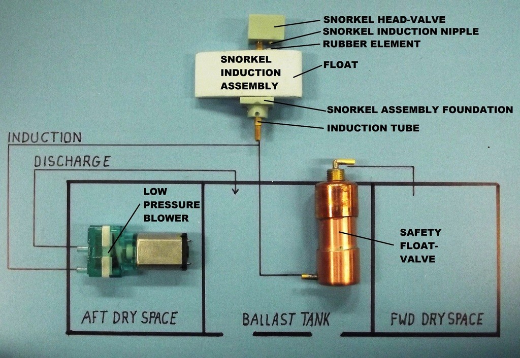
A brief study at this schematic will give you some idea as to how air is either drawn from atmosphere or from the dry spaces within the system. Of note is the safety float-valve. Its job is to isolate the dry spaces from any water that may leak into the induction plumbing – be that leak the result of a faulty snorkel or break in the induction line between snorkel and the MSD. Not illustrated is a conduit between the two dry spaces which makes them common as to their atmosphere.
During the certification process the forward and after dry spaces are represented by short lengths of capped Lexan cylinder, diameter dictated by the type unions used by the ballast tank. The ‘ballast test unit’ is installed within the after dry space.
The job of the ballast test unit is to both power and control the operation of the ballast sub-systems servo and low pressure blower (LPB), a modified two-stage diaphragm pump – this type positive displacement pump has the ability to handle both gas and liquid without damage or leakage.
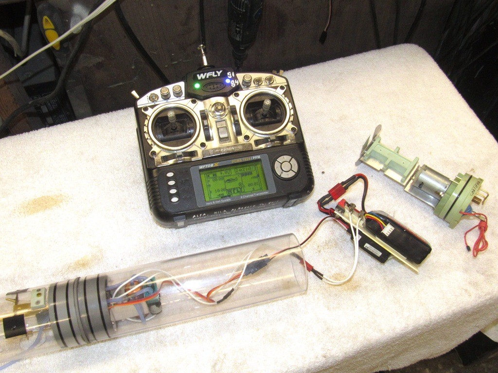
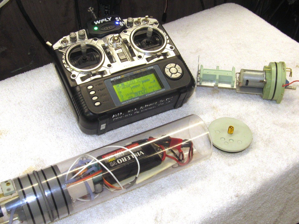
The ballast test unit is outfitted with an 11.1-volt battery, 5-volt voltage regulator (to power the receiver and receiver bus), and a pair of alligator-clips that make up to the LPB’s power leads (a voltage dropping resister establishes the 3-volts preferred by the LPB’s motor). The compact test unit fits within a short length of 2.5” diameter Lexan cylinder as the ballast sub-system is put through its paces in the test-tank.
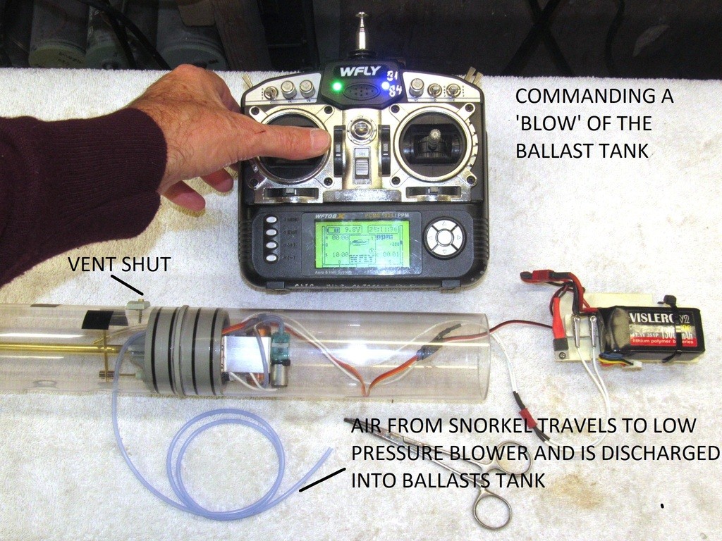
The transmitters left stick, its left-right throws specifically, controls the ballast sub-system.
Center-stick maintains the vent valve closes and the LPB motor off.
Left stick and the servo positions the vent valve open and the LPB remains off – air within the ballast tank escapes and is displaced by water rushing in through the open flood-drain holes in the bottom of the ballast tank.
Right stick and the vent valve closes and the LPB motor runs driving air (either from the surface through the snorkel induction hose or from within the MSD’s dry spaces) into the ballast tank driving the water out the flood-drain holes.
Through calculation, practical testing, and dumb-luck the volume of the ballast tank is sized to contain a weight of water equal to the weight of the water displaced by the submerged portions of the submarine that reside above designed waterline. A dry ballast tank and the submarine floats at the designed waterline. Ballast tank full of water and the submarine submerges and assumes almost perfect neutral buoyancy. By changing the submarines weight with a ballast tank is described as ‘static diving’ -- the submarine requires no other force to hold the submarine underneath the surface.
Before getting into the certification steps, let’s take a closer look at the MSD’s ballast tank and how it works:
To the right is the after ballast union piece that mounts the LPB, ballast servo, LPB limit-switch, and safety float-valve. That brass tube running the length of the ballast tank is a conduit which passes the servo and power wires between the two dry spaces, it also insures that the two dry spaces share the same atmosphere. The after face of the after ballast union is the dry side and makes up to the after dry space cylinder. To the extreme left of the ballast tank is the forward ballast union that interfaces between ballast tank and forward dry space.
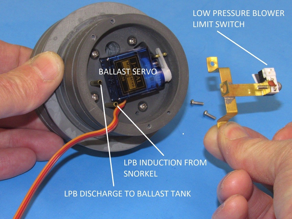
Here we’re looking at the after ‘dry’ side of the after ballast union. The ballast servo operates a pushrod that passes forward, through a watertight seal, into the wet forward face of the union. The pushrod makes up to the linkage that operates the ballast tank vent valve (mounted atop the ballast tank), and an optional emergency gas blow-valve.
Incorporated onto the strap that holds the servo in place is a limit-switch that is actuated by the swing of the servo output bell-crank. The limit-switch closes when the servo travels about 20% to the ‘blow’ position, energizing the LPB’s motor.
Two pass-through brass tubes serve to route snorkel induction and LPB discharge air between wet and dry spaces.
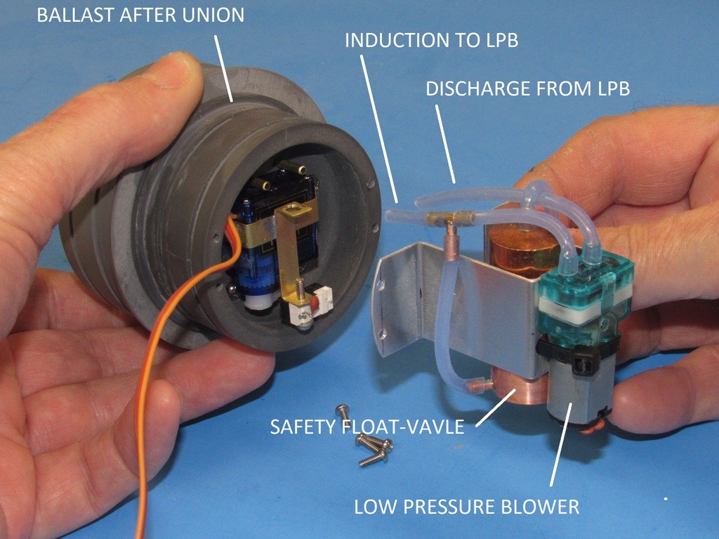
The LPB and safety float-valve attach to an aluminum mount which in turn is secured to the radial flange of the unions dry side. Flexible hose and a T-fitting route air between LPB, safety float-valve and the two brass tubes set into the union.
The safety float-valve permits air to pass into or out of the dry spaces through the induction line, but will close in the event any water gets into the induction side of the plumbing, this to prevent inadvertent flooding of the dry spaces should the snorkel stick open or the flexible line between snorkel and after ballast union develop a leak. Old submarine practice: TWO-VALVE PROTECTION FROM SEA!
Here you see the wet forward face of the after ballast union. Note the foundation at its center, this accepts the blow-valve of an optional gas type ballast back-up should the client elect to add that feature (recommended if the submarine is to be operated in open water, an extra measure to assure surfacing should the model get away from you).
The brass tube induction nipple makes up to a flexible hose that runs out one of the two flood-drain holes at the bottom of the ballast tank and extends up to the snorkel valve, high up within the submarines sail. The discharge nipple pumps air into the ballast tank directly, blowing ballast water out, surfacing the boat.
An encapsulated O-ring, positioned into the tool during the union casting process, makes the watertight seal between union and brass conduit.
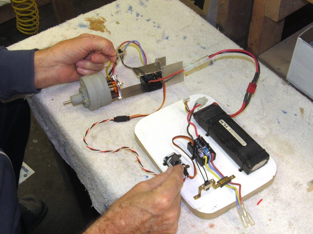
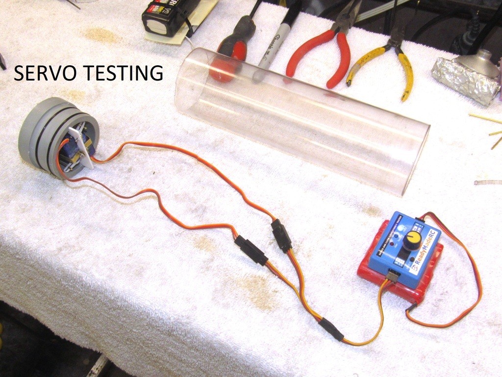
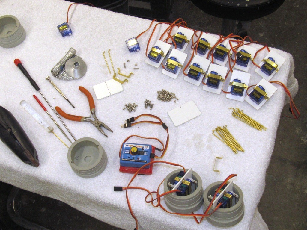
Here I’m demonstrating operation of the SemiASperated (SAS) ballast sub-system elements, the test unit is wired up to the servo and LPB. I operate the devices remotely from the transmitter.
This is pretty much the condition of things during the SAS certification process. For clarity I’ve left the test unit outside its cylinder.
Left-stick – dive.
When the transmitter stick is shoved to the ‘blow’ position, the vent is closed and the servo bell-crank closes the limit-switch causing the LPB to pump air – from either the dry spaces of the MSD or from atmosphere through the open snorkel valve – into the ballast tank, emptying it of water. The submarine assumes surface trim and floats at the designed waterline.
Right-stick – surface.
SAS certification is done with the unit submerged. But before that I do one last leak check with the fully assembled system.
The system is held underwater in the test tank.
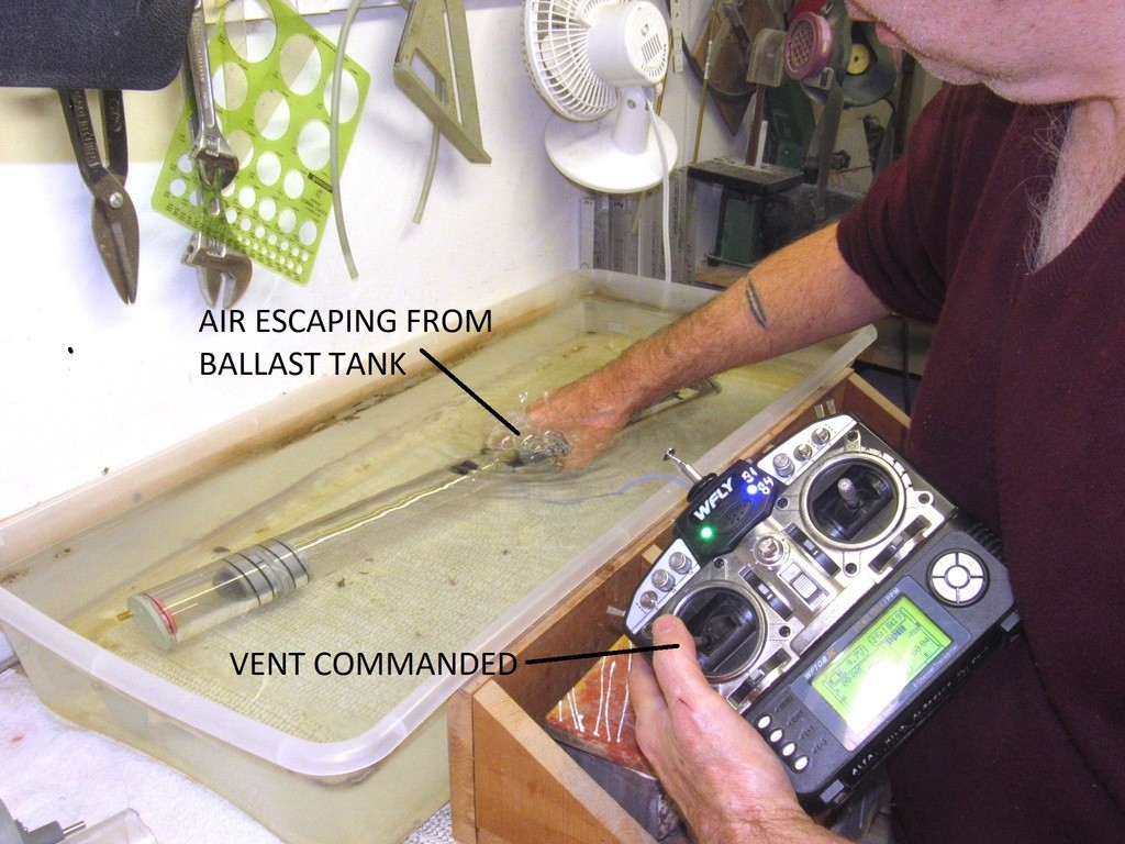
First, the tank is vented, flooding it. The vent valve is checked for reliable operation and the flood rate it noted.
I then command a blow (the induction flexible hose is out of the water so the LPB can draw air from atmosphere).
Once the tank is blown dry I note the blow rate and check for no leakage at the vent valve.
The ballast tank is again flooded, and the external induction line crimped off with a hemostat, simulating a closed snorkel valve. A blow is commanded, but this time the SAS is compelled to draw air from within the systems dry spaces. Typically there is enough volume within the dry spaces to achieve a blow that empties at least 1/3 of the ballast water before back-pressure builds to a point where it stalls the LPB. However, the amount of ballast water is blown overboard is enough to cause the simulated submarine to head to the surface where the snorkel would open once again taking air from atmosphere, unloading the LPB, breaking the slight vacuum created within the dry spaces, and the blow continues till the ballast tank is completely dry.
The system is pulled out of the water and the induction hose removed, the partial vacuum within the system is broken and the system again pushed underwater. This time with the induction tube open to sea, simulating a stuck open snorkel valve and/or a leak in the induction hose. The blow command is sent and the LPB operated till it stalls as its pump is hammered by incompressible water. If the safety float-valve did its job there should be but a few drops of water within the after dry space. Once all test steps are passed the system is deemed certified and ready for packaging.
I barely graduated from High-School, math totally escaped me, but I devoured my shop classes. I LIVED FOR SHOP CLASS! If I had to characterize myself during my public school days: I was the Sheldon Cooper of shop-classes, and just as much a non-conforming jerk.
I don’t play well with the other children, and never will! I learn things the hard way.
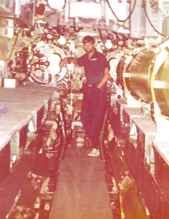
Still a snot-nosed kid I joined the Navy. In the 60’s if you had a heart-beat they swore you in, no questions asked. I did some time in the Fleet as a Torpedoman; qualified on Submarines; and spent the last decade of my career as a salvage and ships husbandry Diver.
I’m not school-smart. However, I can read, am clever, stubborn, tenacious, meticulous (when focused on those things that interest me), and one hell of a model builder. I started scratch-building at age-five.
I’m an intuitive mechanic and, as with all men in my clan, I have smart hands.
It’s genetic. To this day it takes only a whiff of burnt flux, hot green-sand, wood pitch, cutting oil, or blue-print ammonia; the sounds of a machine shop; or the sight of a meticulously blued-and-scratched sheet-metal lay-out to make me smile and nod in appreciation.
Better crawl out of the cave and get some rays on you, alot has changed in the outside world!
Are the twin servos for ballast? I do not know what second servo is for.
couriousocity won't kill the Canadian
Yeah, enough of the cabin-fever for me! I'm going out to play! Time to drop the albino look.
The two servos in the forward bulkhead (removable cap if you will) was one of the improvements Bob wanted to make standard on the new Modular SubDriver (MSD) products. One servo for the bow/sail planes and the other servo for a plane retract mechanism/torpedo launcher/whatever feature.


Comment