Welcome to our forums. For the best in R/C submarine kits, components and accessories, be sure to visit the Nautilus Drydocks
If this is your first visit, be sure to
check out the FAQ by clicking the
link above. You may have to register
before you can post: click the register link above to proceed. To start viewing messages,
select the forum that you want to visit from the selection below.
Note that I've produced two SD's for the Type-23. The longer one is our 'standard' single-motor 2.5 SAS SD that is recommended for most of the modern 1/96 model submarine hulls -- and it's a perfect fit for the Bronco 1/35 Type-23 if you don't want to install practical torpedoes. Though that ballast tank is about five more ounces of water weight than required, that would be compensated for by installing the appropriate amount of foam under the deck, above waterline.
The smaller SD is purpose built for this kit -- it's length short enough to permit installation of two weapons ... sorry, no re-loads!
Heh. Just like the real boat.
David- If I may ask.... I'm used to the old WTC3, 3.5, mod2, etc. I'm looking at the photo of the smaller purpose built SD specifically, but I see two extra hoses on both, which I'm assuming are the for the SAS variant? Also, with these systems, how do the forward and rear dive planes interact (front fixed, rear on some angle keeper, front on servo, or vice versa?). Also front area of system is for air? How does one drive a torpedo fire mechanism from this type of system? Sorry, lots of questions; my knowledge is so stale...
Thanks!
Sam
I took a swift look at the SD, to me it seems that it can be deployed without making it shorter, took one of my launchers in the build, and did some measurements, it can be done, the extra room inside the ballasttank will be usefull since i have a tendency to throw in some extra weight due to the gizmo's.
Talking about the launchtubes, for now i'm busy building them, i'll show you guys the progress sofar.
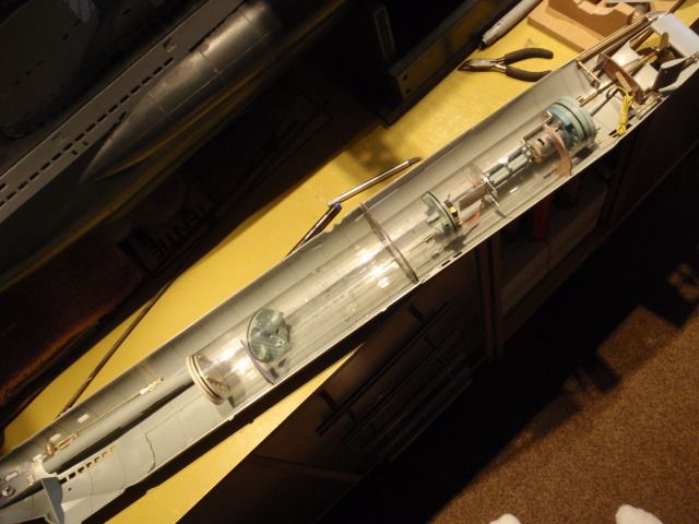
This is my next generation launchtube for firing electric torpedo's, major difference is, stole the lockingball device from David, and added the magnet on the triggerbar, the launchtubes from my type VII are spring assisted, they push the torpedo out, away from the static magnet which is located underneath the launchtube, now the magnet will slide away, which will trigger the reedswitch inside the torpedo, it's on itself will run under power out of the launchtube.
Did numerous tests to see it it will work flawless, time after time i could launch the torpedo, so that's a winner, the copper tube is designed for my type XVIIb, using this design for the XXIII is a lucky bonus.
Problem with those styrene tubes is, you cannot build up your parts from styrene, they will fail after some time, i decided to build up some components of copper, this tube is ready to be glued.
The second tube is still under construction, at the foreground you can see all components needed.
Inserted one of my electric torpedo's, it's a nice fitt, still have to close the end of the launchtube, preventing the torpedo to be shuffed in too deep.
The tube from the lockingball is a bit to high, that can be easely solved with the dremel, i will follow the same way like David did, will use the length to bent it inwards for preventing that the locking ball will fal out of the tube.
All work in progress, still lots of work to do, have to design the levers which will control the triggerbars, now that i've got the SD, i can make a dryfitt to see how this can be done.
David- If I may ask.... I'm used to the old WTC3, 3.5, mod2, etc. I'm looking at the photo of the smaller purpose built SD specifically, but I see two extra hoses on both, which I'm assuming are the for the SAS variant? Also, with these systems, how do the forward and rear dive planes interact (front fixed, rear on some angle keeper, front on servo, or vice versa?). Also front area of system is for air? How does one drive a torpedo fire mechanism from this type of system? Sorry, lots of questions; my knowledge is so stale...
Thanks!
Sam
Hey, Sam!
Just like old times.
Dropping gas as the means of displacing the air from within the ballast tank I use a small air-pump (with the ability to ingest water without damage), taking a suction from either a snorkel protected induction line or air from within the SD itself to blow ballast water. As the pump is in the after dry space I need to run both the snorkel induction line and discharge line to the ballast tank atop the SD. Hence, the two flexible hoses you see. The forward dry space is for the battery. For more dope on the SAS ballast sub-system, read this: http://support.caswellplating.com/in...--how-it-works
As always (with the exception of the Moebius TV SEAVIEW) bow planes are on independent control loops: the stern plane is tended by the driver or the angle-keeper. The bow/sail planes are tended by the driver or a depth-keeping device -- do not interconnect!
Thanks for the links, David. I have downloaded both pdfs and begun reading them. On my OTW Type XXIII, I drove the front planes with a servo, and used the angle keeper on the rear planes. With this boat's size, I wasn't sure if one set of planes would be enough to dive the model. Also, if you recall, that boat used an onboard compressor to control filling and emptying the ballast tank. For this kit, I like the fact that the ballast system leaves enough room to add weapons.
The XXIII kit that I ordered from Mike here showed up yesterday, so I have been able to study the hull parts included in the kit, and the details. I'm impressed by the sheer size of the model, and the details look pretty good so far. A couple things already noted elsewhere; schnorkel head is a bit weak, the tubes for the schnorkel could probably be replaced, no horseshoe life ring, the emergency raft hatch at the front of the tower is sparsely detailed. I like that they included some of the trunking under the turtledeck, and some of the other details like the raft and the torpedoes (might be nice for a diorama). I'll be watching this thread carefully as you and Manfred continue to flesh out this conversion process.
Thanks again!
The fun bit is, David has taken the waterline cut, i'll try to use the cut that came with the model and slide the SD in, in the mean while avoiding the arrows offcourse, the SAS system is a great improvement compared with the gassystem, less things to worry about (adverticing).
For connecting the torpedotubes mechanically you can read my thread about the 212, works fine for me.
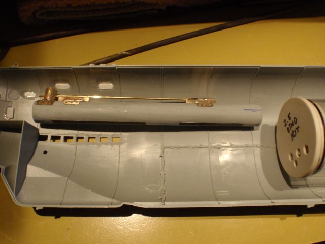
From the minute i had the model, i cutted these, the bigger one's will be inserted at the beginning of the split, the smaller one's will support the SD.
Here you can see one of the bigger pieces inserted into the front part of the XXIII, since i had no SD i just signed of the true center for the shaft.
Today i cutted out those bulkheads and supports, remember this is a standard 2,5" SD, not the shorter one, i'm still able to place my launchtubes inside without space problems.
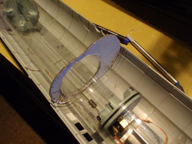
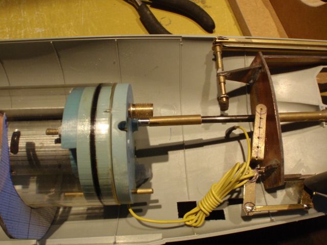
A more close up view of the frontpart, don't know if the launchsystem from David needs more room, for me this will work.
The plan is, just using small machine screws for holding the bigger bulkhead, giving me access inside the hull when removed, the fit is not that tight, so i can slide my SD in/out with no problems.
At the beginning i didn't knew that the shaft of the SD would be off center, solved this by turning this bulkhead upside down, this way the shaft will slide into the copper connector on my propellorshaft in one move.
When all bulkheads and supports are secured i can make my connections in such way that they will "click" on by using the magnectic couplers, the more tricky part will be, to make this happen at the launchtubes.
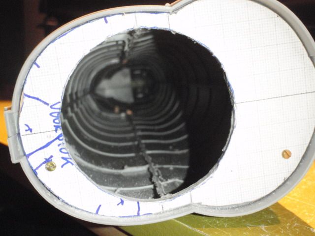
A peek inside the front gutts, there is plenty of room inside to play with the lead and foam, the bigger bulkhead can be taken off for more access when needed.
I ran the numbers of the actual G7E torpedo against the one provided in the kit and found the kit torpedo to be too fat and a bit longer than the documents I used -- even more room up there for a practical torpedo, guys.
Man! Manfred's inching ahead of me, I gotta get hot! Working up fittings kit masters today.
I shuffed those torps aside, i know my electric one's have the right sizes compared to a 1:35 scale.
I've done even more, but will not show this yet, stacked up the instant pizza's, checked the microwave, got me some tray's of red bull, am i preparing for something?
I ran the numbers of the actual G7E torpedo against the one provided in the kit and found the kit torpedo to be too fat and a bit longer than the documents I used -- even more room up there for a practical torpedo, guys.
Man! Manfred's inching ahead of me, I gotta get hot! Working up fittings kit masters today.
David
[ATTACH=CONFIG]19281[/ATTACH]
David-
If the torpedoes are too fat, does that mean we should scrap the styrene torpedo tubes that came with the kit as well? hmmm... I guess if you go with David's weapons rig, it doesn't matter, as the tubes are part of the system...
I think it was Warpatroller who suggested that I was going to (or have in the past) used kit parts as masters when working up fittings kits. Let me make something perfectly clear:
To take another man's (or corporations) work and copy it for personal gain -- without their express permission -- is, at the very least, illegal and is, without a doubt, immoral! If you are such a no-talent, mouth-breathing, pretender that you have to copy others work and make it your own, you have no business calling yourself a Model Builder. The only kit parts I have copied into a fittings kit ... EVER ... were the control surfaces of the recent Moebius 1/72 SKIPJACK kit, and that done after securing the permission of the guy who designed that kit for Moebius, as well as getting that companies CEO's permission!
I do not pirate anyone's work. And if I catch anyone doing it, I blow the whistle ... long and loud!
(and what the hell is that guy over at the SC site talking about, describing the model 'he built' -- an item pooped 3D copy machine!!!???.....)
This morning I got to work on the control surface masters (NOT using any kit parts ... I have not had a word with any of the good Bronco folk's about such use). The blanks built up by two laminated pieces of 40 lbs. RenShape. The assembled blanks create a reference plain needed to assure symmetry as I cut, filed and sand the blanks to correct foil section, using the dark perimeter outline as a datum.
And that's a shortcoming of the kit, the hydrofoil shape to the stern planes and bow planes is a bit off. My masters don't suffer that shortcoming. I've elected to go with 1/8" control surface operating shafts for the stern planes and bow planes as they are subject to collisions on this subject. The rudder is well protected, so its operating shaft will be 1/16" (this will make installation of the eventual linkage components within the tight confines of the upper rudder support piece a bit easier).
I also poured a thinned two-part filler into the stern to form the propeller shaft foundation master.
I think it was Warpatroller who suggested that I was going to (or have in the past) used kit parts as masters when working up fittings kits.
(and what the hell is that guy over at the SC site talking about, describing the model 'he built' -- an item pooped 3D copy machine!!!???.....)
David
I think I had used the word "duplicate" when talking about the Bronco propeller. By that I meant you scratch building a prop master that resembled the Bronco prop. I am aware of your stance and feelings on duplicating the work of others, and that you do not directly use kit parts as master parts. I wasn't suggesting that, though it may have been misunderstood that I was.
I have to comment about the whole 3D modeling thing. Bronco, as well as most of the injection molded model kit producers, "build" their subject models in 3D on the computer. The Bronco XXIII started life out as a 3D wireframe mesh in a computer. Renderings of it are even shown on the box! Bronco would have also used either a 3D printer or stereo lithography to produce the trial parts, before producing the injection mold tooling for the kit. Some people may be under the impression that "building" wireframe models in the computer is very easy, or can be done with a few mouse clicks and out pops a model. If it was so easy good 3D modelers, who really know what they are doing and are fast, wouldn't be paid $125K to $150K a year salary.
It takes a certain level of skill and time, to create a good wireframe mesh in the computer. It is tedious work and requires meticulous attention to details, to build an accurate 3D model of a complex subject with a high level of detail. Granted that guy's Nuke boat over at SC is an easier subject to model than say a WWII boat.
Some of the software tools actually resemble their real world counterparts, in functionality, such as bandsaws and lathes etc. One can even "sculpt" objects in the computer these days. It is another art form, but in the digital realm.. The real work is in building the wireframe model in the computer. Once it is built, then printing it out afterwards, is the easy part (if you have the money to pay for the rather expensive printing).


Comment