
- Leelan
-
Almost forgot! There is a bit of instructions not included with the kit. They are only online should you be looking hard enough to find them. They have to do with the tower running light assemblies:
- Leelan -
I have the doors installed in my static build of this kit. It turns out that with the magnets in place you can't open both doors at once wide enough to release both torpedoes. Very Angry
I'm was planning on adding the inner tube doors and rigging up a system to pull both doors open and lock them in place. But with those magnets preventing that I will have to rethink this. I don't think moving the magnets further aft along the door will work. The strain of fighting the magnets might be too much for the styrene either in the long run or the short run.
I wonder. Will foam keep its spring after repeated use? Maybe a gentle spring . . . Oy.
- LeelanLeave a comment:
-
Romel,
You're getting warm on the door mechanism, try again.
As for using magnets to keep the doors shut, once my torpedo is launched it has to come near the torpedo door, which holds a magnet in your theory, hmmmmm, my torps are magnetic activated, so it will shut down my torpedo.
Must be a funny sight, two torpedo's halfway out of your type XXIII, and then running the gauntlett for evading depth charges, a Uboot captain's wet dream.
The work will continue at the Skunkworks, be patient.
Manfred.Leave a comment:
-
Nice operating system.
The torpedo doors are closed when the pin on the turntable is in 2 o'clock clock position and open in the 6 o'clock position. Just add another pin for the other door. But only one door will be open at one time.
Think you have to open up or lengthen the forward portion of the internal guide rails to the length of the entire door to enable the turntable to rotate in opposite directions.
From above with both doors closed the operating pins on the turntable would be in the 9 and 3 o'clock position respectively. If you wamt to open say the starboard door you rotate the turntable clockwise 90� so that the S'board pin would be in the 6 o' clock position. The pin on the port tube now goes to the near 12 o'clock position. Two opposing magnets on the inside of the door would ensure the adjacent door remains closedLast edited by redboat219; 04-05-2013, 09:57 PM.Leave a comment:
-
My sweet revenge for my lost fortune for buying your stuff, hahahahahah
Manfred.Leave a comment:
-
This week i ordered some stuff from the webshop, awaiting the stuff to be delivered i started with building up the launchers, and found a simple solution for opening the torpedo doors.
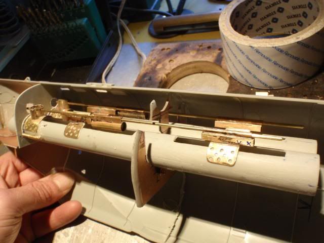
Building the launchers was a fairly straight job, i allready had made some components, for now everything is secured by CA, just in case i have to adjust things, i can break it free easely.
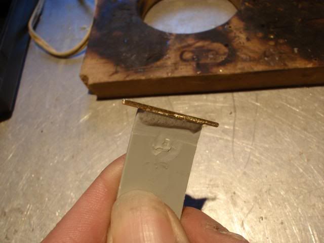
Making the doors work was a different story, first i replaced the plastic hinge for a more robust copper tube.
Lined out the door to get the best fit.
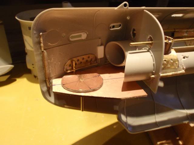
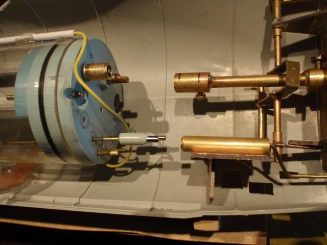
This is my solution for opening the doors, with my other subs they work with a spring and wires, since you can't get inside anymore i had to design a more robust system, which will be using low maintenance, and limited moving parts.
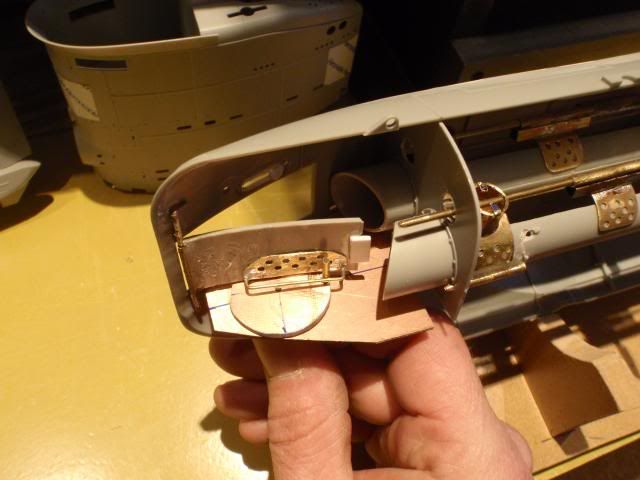
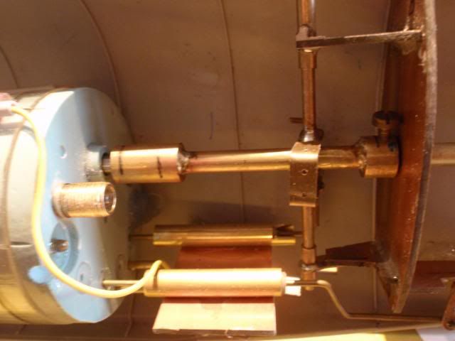
By turning on the shaft, which is connected to the circel, the little rod will pull the door open, in closed situation this pin will keep the door locked at it's place.
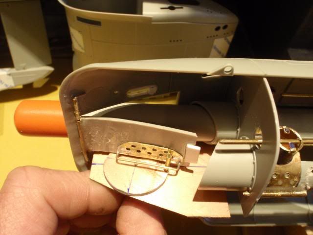
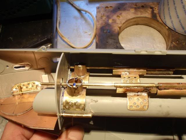
Shuffed in one of my electric torps, to test if there is enough clearance, i have to open up the door just across the centerline.
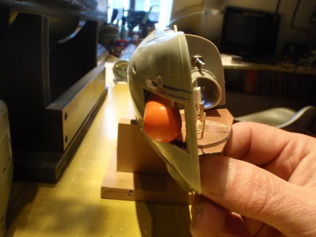
A view from the front, as you can see there is enough room for the torpedo to get out of the launcher, to get this much room i had to place the hinge as far as possible on the door.
For now everything is build raw, i do this each time, first make a testcase, try it, and make the final version, still a lot of work for the Skunkworks.
Manfred.Leave a comment:
-
Manfred,
i tend to over think and miss the simple answer. Using a scale and pulling until it separates is a simple answer. Here I was thinking there was a mathematical formula. Lesson learned, thank you very much.
Peace,
tomLeave a comment:
-
Sam,
It had to be a simple connection and yet relaible too, the launchers will be indeed the next chapter, they allready exsists in the raw, first have some glueing to do before i start with those, one step at the time, be patient.
Andy,
Those new swearwords i've allready learned during this build, i will close up both halves only after some rigurous testing, for now tape will hold her together.
Tom,
I've used a small portable electronic scale weight, you can attach objects to it by hanging them on the hook, i've attached the hook to the frontpart and started to pull untill both halves seperated, the peak weight was registred on the scale, giving me a readout of 1,8 kg pullingforce.
Today i've changed the positions of the magnets, that means, lesser material between the magnets, now i need to pull a wopping 5,5 kg to get both halves seperated, that should do the trick.
Opening up procedure is easy, with the boat on the stand you gently try to break the backbone by forcing both far ends down, this movement will seperate both halves.
Manfred.Last edited by MFR1964; 04-01-2013, 10:44 AM.Leave a comment:
-
-
Nice conversion on this boat.
Can't help but think you're going to learn a few new swear words if something goes in the stern of the boat mind you.Leave a comment:
-
I see it Manfred. That's how I thought you would have to do it. Make a "key" on each side of the shaft, and place a "cover" it so that it doesn't get sloppy...
All you need to do (as I saw in your video) was rotate the prop to make sure the "keys" match.
I'm looking forward to seeing what you are going to do for the torpedoes...
thanks!
SamLeave a comment:
-
Tom,
I did some testing after your remark, you need to pull 1,8 kg of force to get the hull parts seperated, overall weight of the sub at this moment is 1,38 kg.
When doing this test the SD did not came out of the back hullpart, which is logical, the SD itself is connected by two other magnets on the steeringrods, i still have to add three magnetical connections in the front part, the steering of the front divingplanes and the launchtubes.
All in all, when completed, both halves will be held together by a total number of 9 pair of magnets, i'll probably repeat this test after i've placed those connections simply to see what the outcome will be, i'm not really afraid seperation will happen after a emergency reverse.
Manfred.Leave a comment:
-
Manfred,
Just thinking this through, and I love what you have done, would there be a chance if you needed to do an emergency reverse that the forces involved would separate the halves? you could place a simple pin in to prevent a disconnect and not destroy the easy access.Leave a comment:

Leave a comment: