
David how come you didn't use an inner plug like the one you use with your Skipjack?

-
-
Ellie was absolutely stunning! Usually one would look at what's in the foreground but not in this case!!Comment
-
You're not waiting for an argument are you, Myron?!...
Yup. She left an impression on us all; we are better people for the experience.
She grabbed ahold of this young, wild-ass Torpedoman/Diver, got me straightened out, domesticated me, and drummed in marching-orders that I follow to this day. No greater gift.
DavidWho is John Galt?Comment
-

Who is John Galt?Comment
-
Make it simple, make strong, make it work!Comment
-
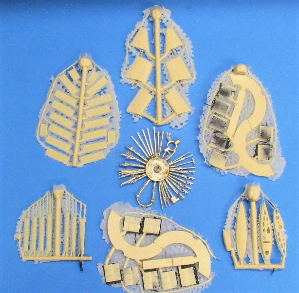
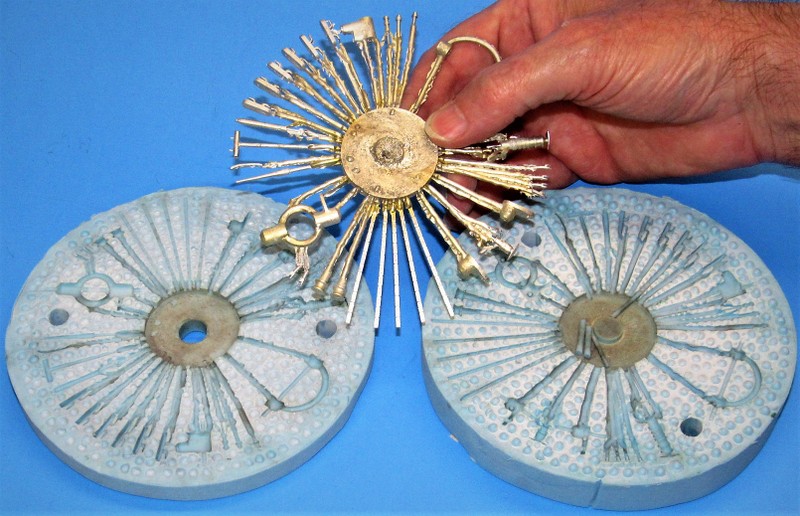
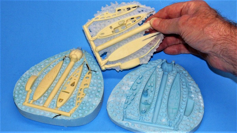
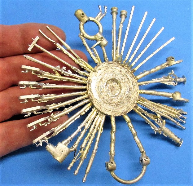
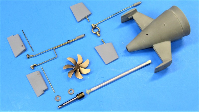
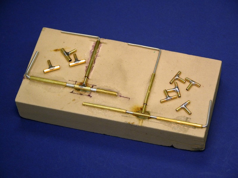
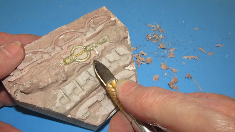
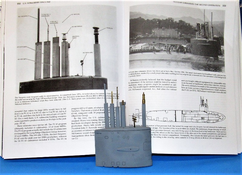
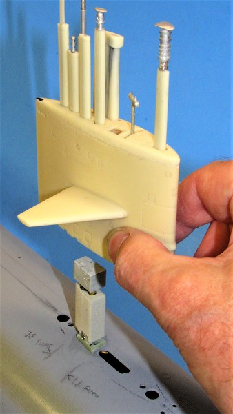
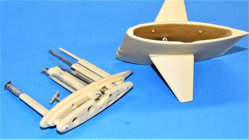
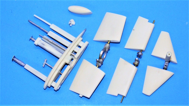
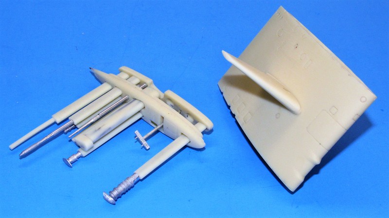
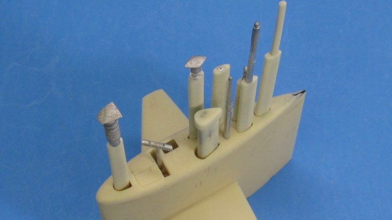
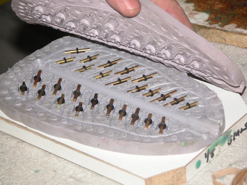
Small metal parts that require machining are best secured in a firm, aligning support, or 'fixture' -- a structure to hold the parts as they are drilled, taped, milled, or polished. This tree of spin-cast metal parts for a 1/96 STURGEON kit is an example of where a fixture is best employed to hold parts that require machining.
Though most of the parts seen here, once snipped away from the sprue, are adequately secured between pinkies or simple hand augmentation holding tools like tweezers, hemostat or pin vice chuck. However, on this tree are five items that will become elements of the models control surface linkages and will require a purpose-built fixture to hold them in place while they are machined.
What is a 'fixture'?
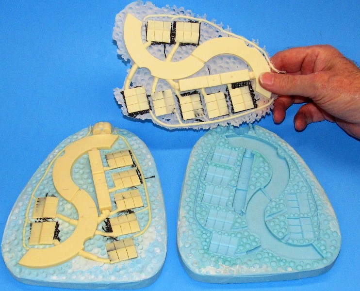
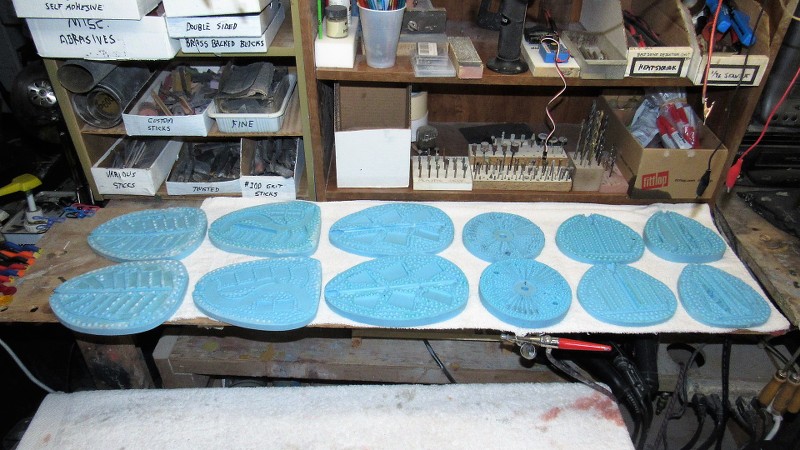
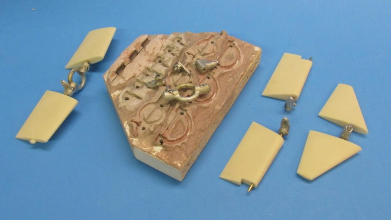
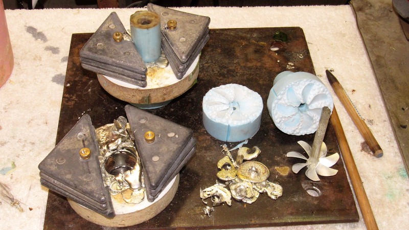
A two-jaw milling, table or bench vice is a fixture; as is a simple set of securing strong-backs pressing the work down securely on the bed of a milling machine. In production work, where not only registration of the work to the cutting tool is primary, the supporting fixture may also accommodate duplicate parts, thereby speeding production. Such is the case with the Bondo fixture I made to hold the white-metal yokes and horns that accompany the eventual 1/96 STURGEON kits to be available this year from Nautilus Drydocks. Nautilus Drydocks Online Store (rc-submarine.com)
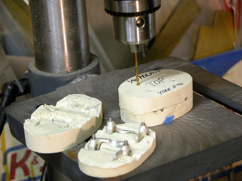
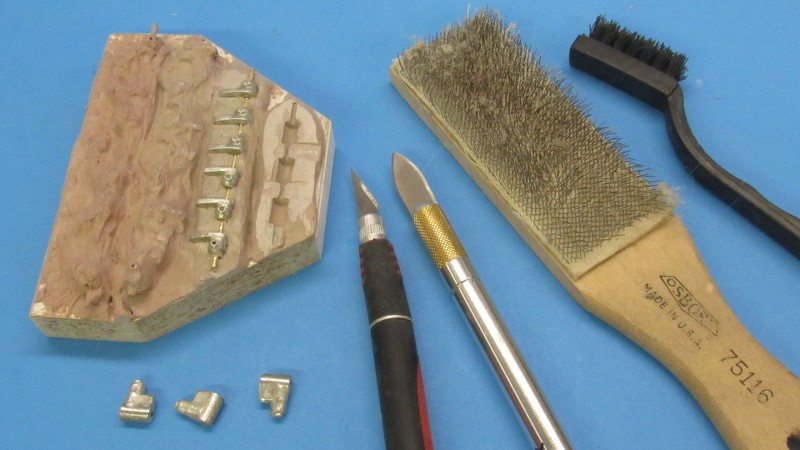
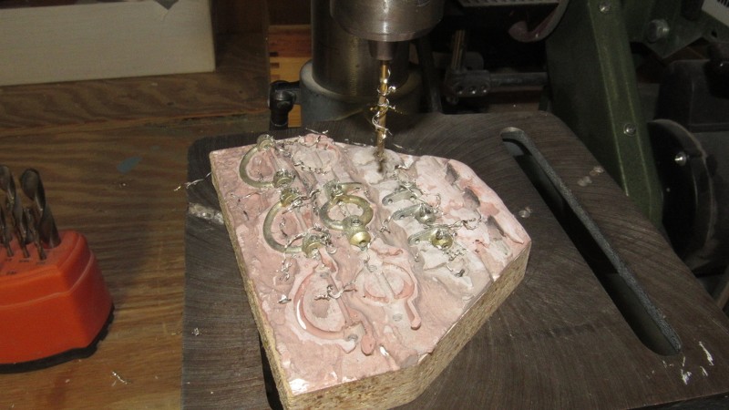
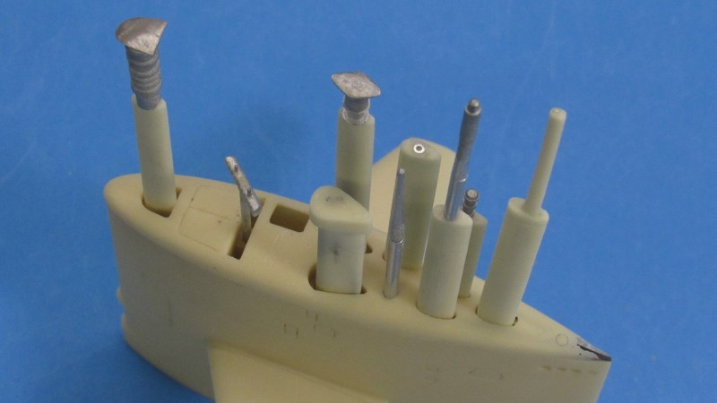
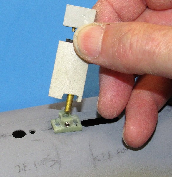
Properly defined as a fixture, this device permits exacting holding of the raw metal pieces while the parts it holds are drilled and tapped. This fixture permits simultaneous machining of three sets of metal parts with one sitting.
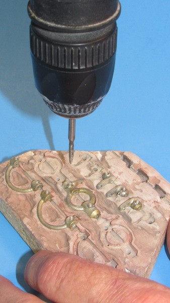
All of the operations involve punching holes, then tapping them with a 4-40 thread. The fixture assures a rigid mounting of each part while it is machined; a mounting that orients the desired bore of the hole perpendicular with the drill bits longitudinal axis.
The initial hole is done on the drill press followed by a variable-reversible hand-held drill driving the tap to create the threads. All drilling and taping is preceded by a drop of 3-and-1 oil. Any burs left around the bores are knocked off with a moto-tool.
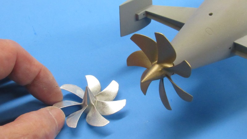
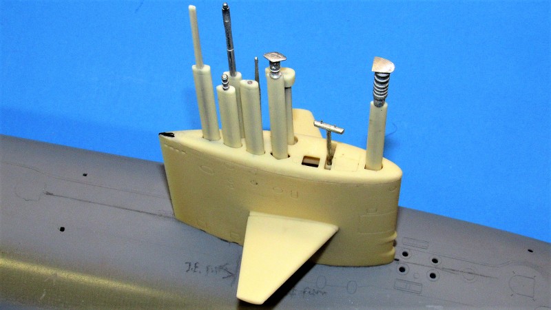
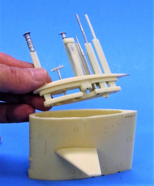
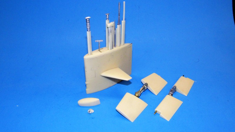
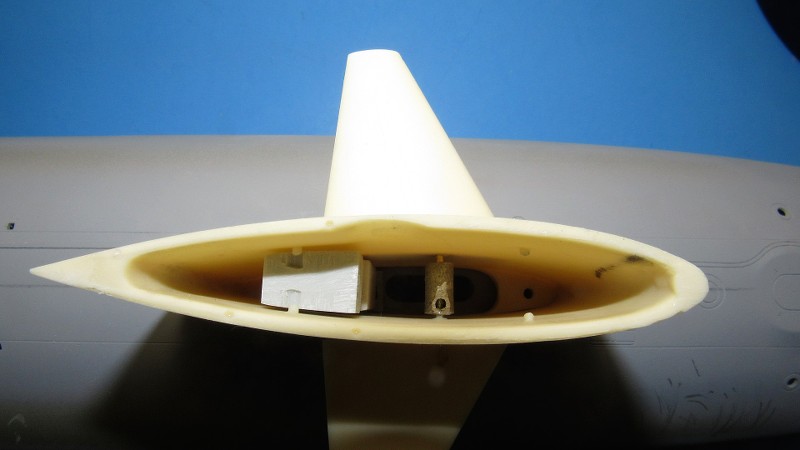
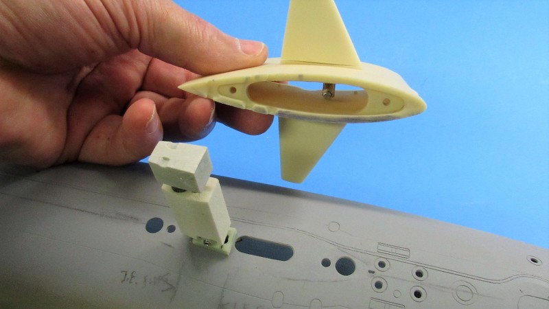
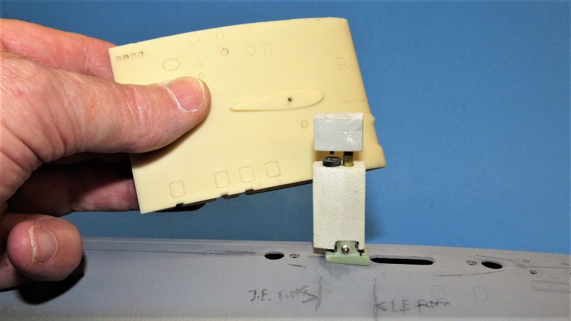
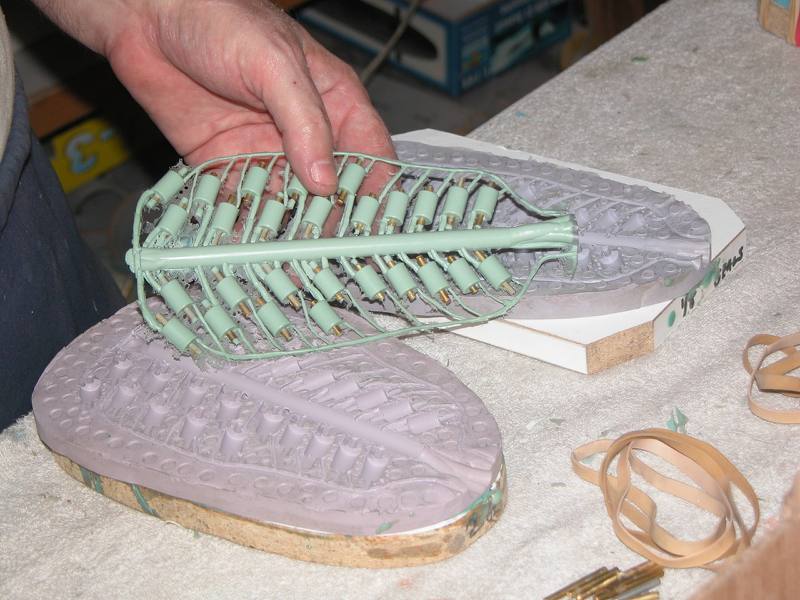
This is how the metal parts are used, as elements of the control surface linkages needed to make the 1/96 STURGEON model a practical r/c submarine. The need for metal -- with its able to take the stress of repeated motion without significant ware or breakage -- is what drives the requirement for a stout holding fixture in the first place. Small resin or injected plastic parts can be hand-held. Not so with parts made of metal: even a soft one like white-metal is best handled via a purpose built fixture.
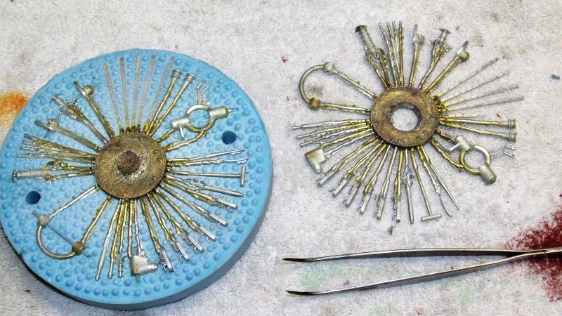
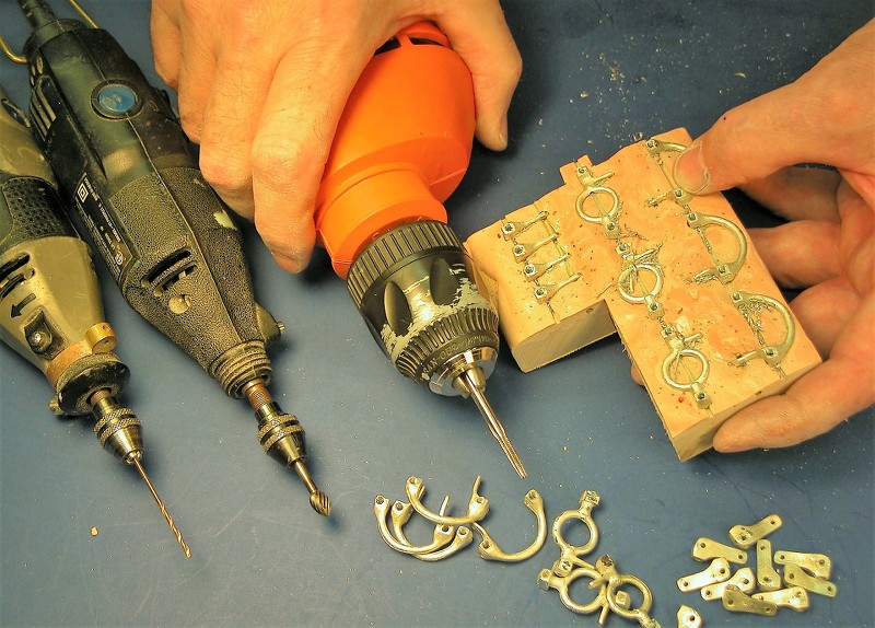
Fixtures are differentiated from 'jigs' in that a fixture holds the work, but does not guide the cutting tool. Jigs, on the other hand, not only hold the work in proper position, it also guides the cutting tool into the work. Such as this jig (top of picture) made to hold die-formed straps securely as a drill bit is guided into the work.
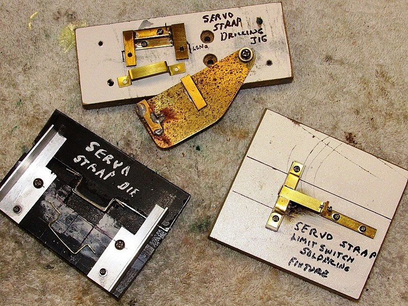
This jig is used to machine threaded bores into the metal yokes for the 1/72 ALFA and 1/96 THRESHER/PERMIT kits. What makes these two tools a jig and not a fixture is that they not only hold the work, but also guides the cutter -- just one of several defining characteristics between jig and fixture.
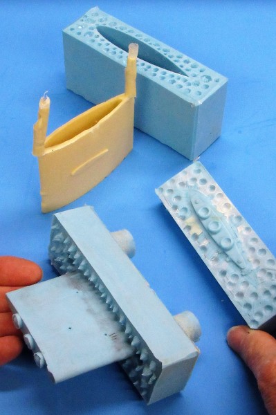
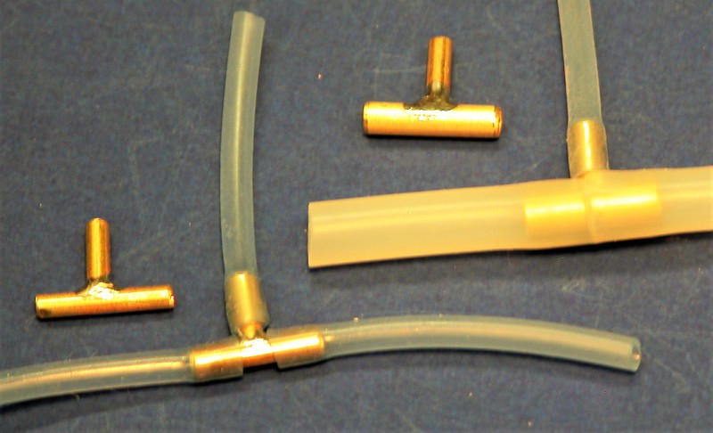
Jigs are also defined as tools that hold two or more parts in correct alignment for joining (soldering, gluing, welding, riveting, screw fasteners, binding, etc.).
For example, this assembly jig is used to produce three-way 'T' fittings for pneumatic or hydraulic systems.
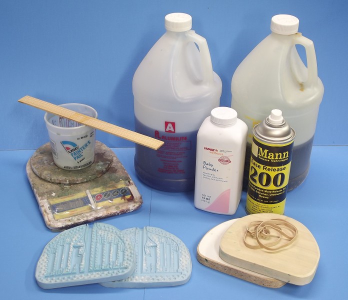
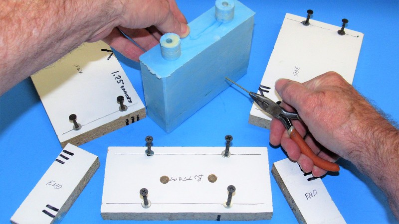
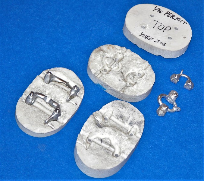
The 1/96 STURGEON control horn and yoke holding fixture was given form by embedding half of each part -- temporarily used as masters -- in Bondo, the Bondo secured to a stout foundation, in this case .5" thick shelving board that had been keyed with shallow holes to give the cured Bondo something extra to hold it in place once cured hard.
Note that I've created a fixture that can handle three sets of parts at once. Time is money!
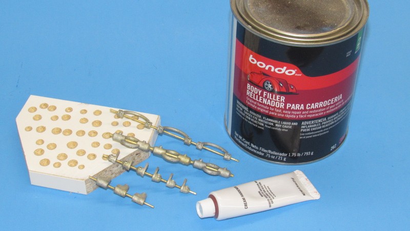
To ease removal of the parts after creating the cavities they nestled in from the rather tenacious Bondo I first coated them with wax.
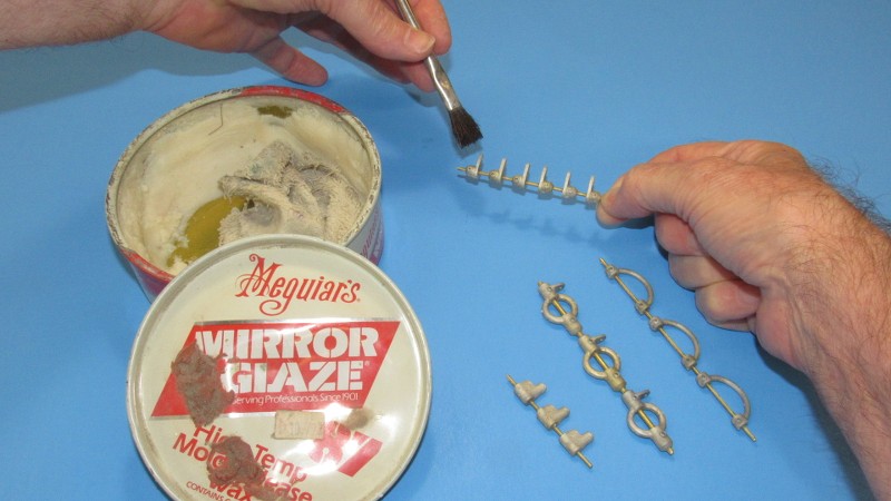
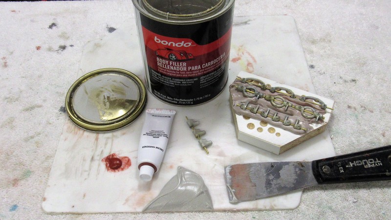
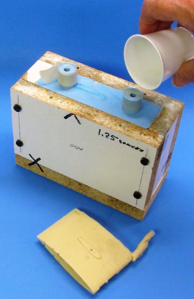
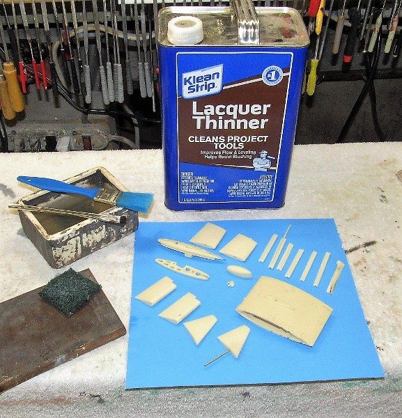
Once the parts were set in the first layer of catalyzed Bondo a second application of lacquer thinned Bondo was brushed on to completely cover the work -- this to insure that Bondo got into every crevasse missed during the initial embedding.
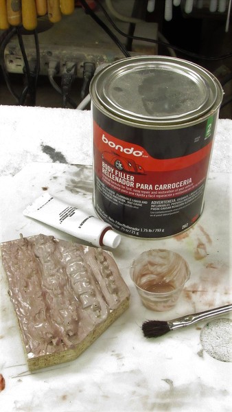
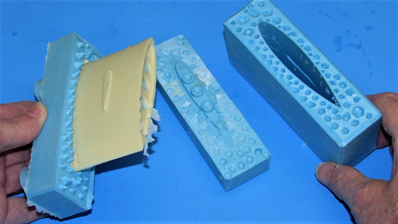
After a few hours under a heat-lamp, the Bondo was as hard as it was going to get. At that point I chipped away the hardened Bondo atop the parts.
This part of the job would have been a screaming nightmare had I not waxed all the parts first!
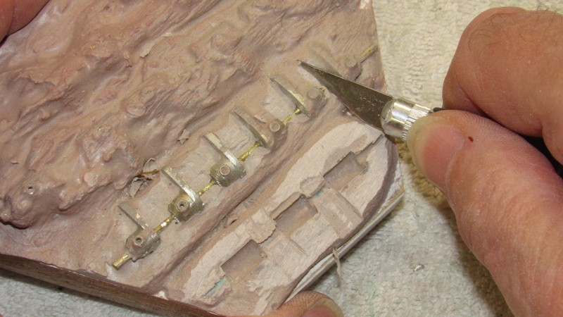
And, finally, after all that nonsense, the fixture put to work machining production kit parts.
 Who is John Galt?
Comment
-
I love this "Old School" stuff David!
If i were only 40 years younger and had the tools, space and the shop and most IMPORTONLY your talent and skills, I would really love to build submarines using your methods!
You are the MASTER!
Rob
"Firemen can stand the heat"Comment
-
Who is John Galt?Comment
-

Who is John Galt?Comment
-
This is my next boat.Of the approximately 40,000 men who served on U-boats in WWII, it is estimated that around 28,000 to 30,000 lost their lives.Comment
-
AN IMPROVED PUSHROD SEAL
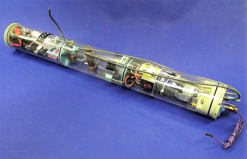
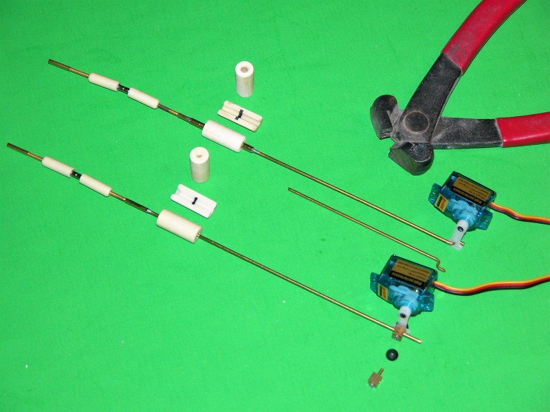
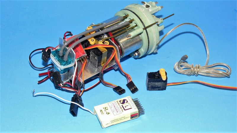
Two of my old watertight cylinders (WTC) were recently pulled out of long-term storage and readied for shipment to new homes. The 2.5" diameter unit was unique in that it had three motors and was used aboard my 1/72 FOXTROT class model. The smaller, 2" WTC, featured two motors and that unit used aboard my little 1/72 Type-7 r/c model submarine.
We've been producing WTC systems for over three decades, and in that time, they have seen much improvement and enhancements. Recently I improved the seals used to make watertight the servo pushrods that form part of the model submarines control surface linkages.
I'll chronicle here the installation of those new seals as well as a quick look at what it takes to re-certify a retired and upgraded WTC for use.
What makes r/c submarines unique from all other r/c vehicles is the need to 'keep the water out'. It's not enough to provide the watertight enclosure -- typically a length of transparent Lexan cylinder capped with cast resin bulkheads at each end -- the system also requires watertight seals to pass drive shaft(s) and pushrods. Internal bulkheads divide the system into three separate compartments: forward dry space, where the battery and mission switch reside; ballast tank; and after dry space, where most of the control and propulsion devices are located.
About twenty-five years ago I started mass producing pushrod seals through the expediency of casting an O-ring within a resin body.
Typically, this type of pushrod seal is secured within the after 'motor-bulkhead' of the system with RTV adhesive. The RTV around the seal body, and the O-ring within the bore of the seal effecting a water barrier between sea and WTC interior. The internal O-ring making an interference fit between itself and the pushrod. However, the use of only one O-ring, over time, results in a loosening of the fit between seal and pushrod and leaking results. Recently I resolved this pushrod seal design shortcoming by simply employing two, not one, O-ring within the seal body.
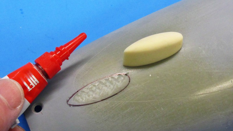
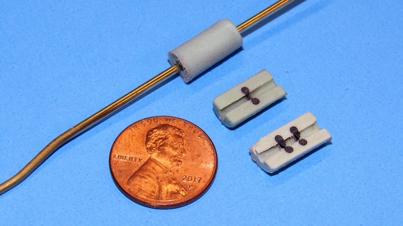
And here you see the difference between the two versions of the pushrod seal. No need to create new tooling for the upgrade. Just jam in two instead of one O-ring during tool preparation. Make the pour and extract a dual O-ring pushrod seal. Simple as that!
The single and dual O-ring pushrod seals share the same body geometry. Only difference is the number of encapsulated O-rings within.
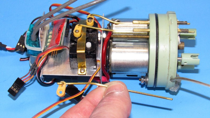
This particular motor-bulkhead featured three direct-drive 380 sized motors that drove my 1/72 FOXTROT model. A friend needed it for his recently completed FOXTROT model -- I had not operated my FOXTROT WTC for over ten-years, so I sent it somewhere where it would see further good use.
(I pulled the 75mHz receiver from that WTC and kept it for myself. Yeah! Oh? well... screw him, tough **** -- he can come up with his own receiver. 75mHz equipment is no longer in production and has to be husbanded... 'My Precious!!').
So. re-certification started with a function test of all the devices: servos, angle-keeper, battery monitor-fail safe, electronic speed controller, low pressure blower, and battery eliminator circuit. During those checks I found that the rudder servo was dead... tits-up... deceased... broke-****... kaput!... had assumed room temperature.
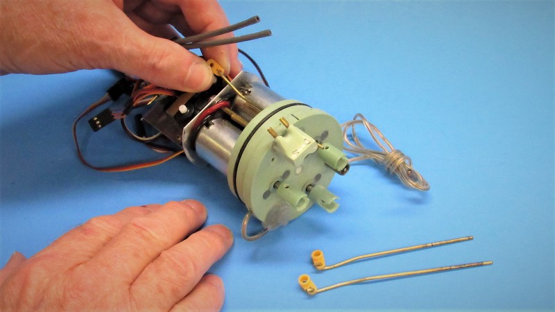
Here, just forward of the pulled receiver, you see the replacement servo ready to be installed.
Replacement of the bum servo started with removal of the control horn and pushing it and attached pushrod aft and out of the way. Then the brass retaining strap was removed. It was then a simple matter to yank the offending servo -- hurling it viciously against the shop wall -- and install the good servo. The strap was made up. Hobbies are great stress relievers!
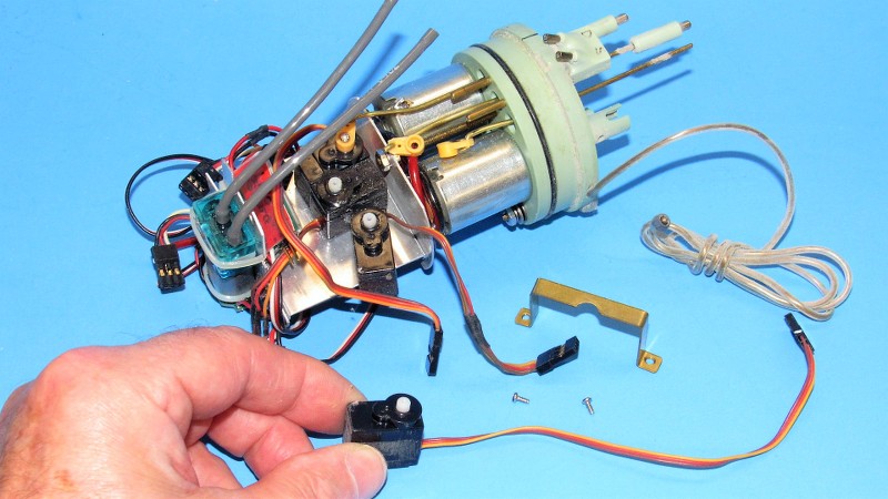
The newly installed servo is tested after being cinched down with the common brass strap used to hold all three servos down securely on the device tray.
Note that two of the pushrod horns have already been popped off their servos and those pushrods pushed well aft. The after ends of the pushrods are now well clear of the after face of the motor-bulkhead, this to permit application of a torch flame without damage to the motor-bulkhead itself.
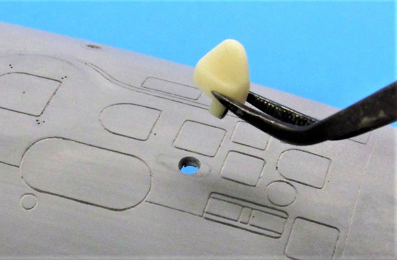
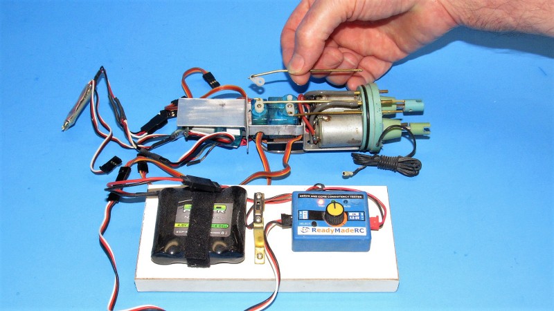
In order to pull the pushrods out of their respective seals I had to clear the magnetic couplers from the after, wet side of each pushrod. I applied heat to an extended pushrod with a torch till the CA holding the magnetic coupler failed. With a little care, by pulling the pushrod aft as far as possible, provides enough distance between torch flame and motor-bulkhead to prevent damage to both motor-bulkhead and magnetic coupler, as you see in this picture.
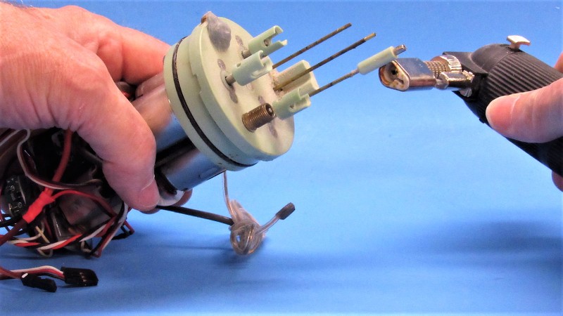
The bare pushrods were then pulled forward and clear of the seals and motor-bulkhead. If need be, to protect the after face of the motor-bulkhead from flame, a wet hunk of rag would be used as a heat-sink/flame barrier.
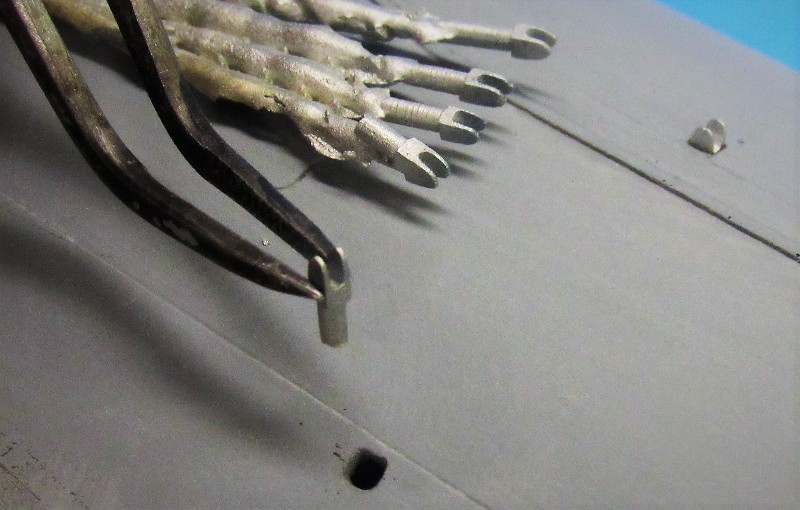
Popping out the old, single O-ring, pushrod seals was an easy mater as they are secured and made watertight within the motor-bulkhead by flexible, relatively weak gripping RTV silicon gasket-making 'glue'. You see me using a short length of brass .25" rod as a pushpin to force each seal aft and away from the motor-bulkhead. Easy-peasy.
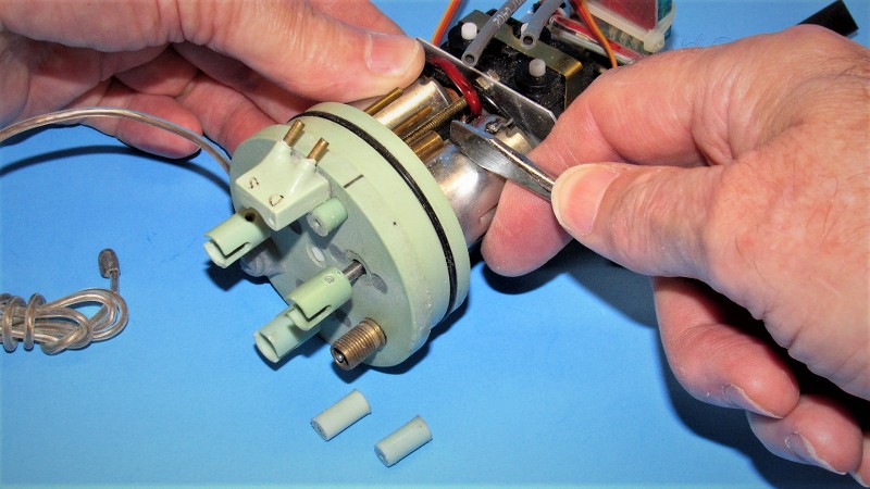
Swap out of the three pushrod seals was a straight-forward operation and only took a few minutes.
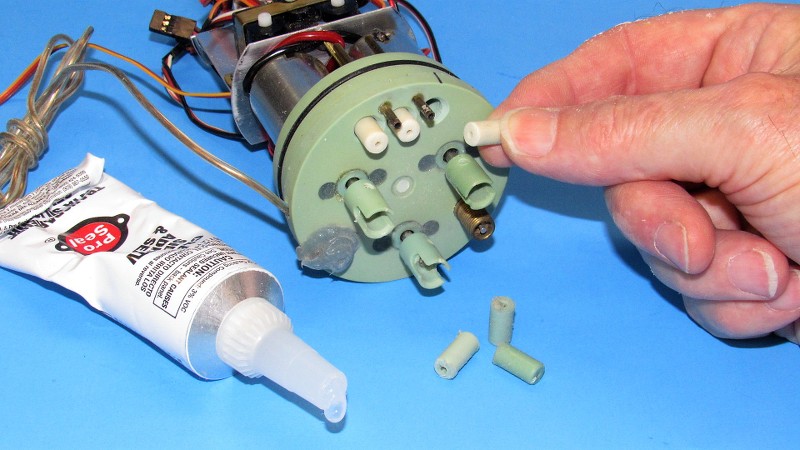
A length of .063" brass rod was used as an 'insertion tool'. I mounted a seal on it, slathered on some RTV, then jammed that sucker in there! Didn't even have to buy it dinner!

Before re-inserting the pushrods, I cleaned them up with a wad of '000' steel wool. Each was then coated with silicon grease.
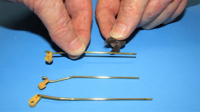
... and inserted.
The same operation done on 2" WTC's pushrods. As each pushrod was pushed through its respective seal, and the forward control horn made up to the servo, the servo was cycled back and forth with the aid of a 'servo setter'. Any binding between pushrod and seal was reduced by careful bending of the pushrod, up-down-left-right, at its forward end. An acquired skill, I can assure you.
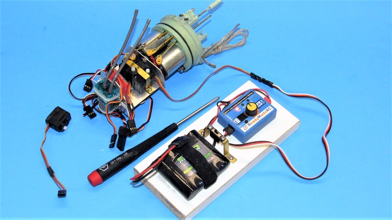
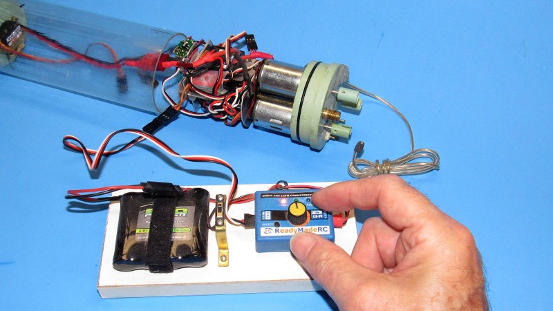
Re-certification included checking for proper motor and drive-train operation. The propulsion battery was hooked up to the ESC, and the servo setter made up to the ESC's lead that normally would make up to the receiver. In this usage the servo setter is used to command motor direction and speed, just as though you were using the transmitter throttle stick -- but without all the hassle of breaking out the transmitter and hooking in the (now removed) receiver.
Testing of the LPB was done the same way.
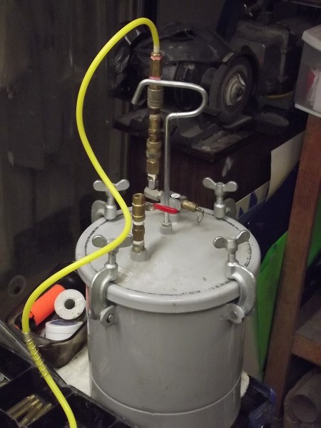
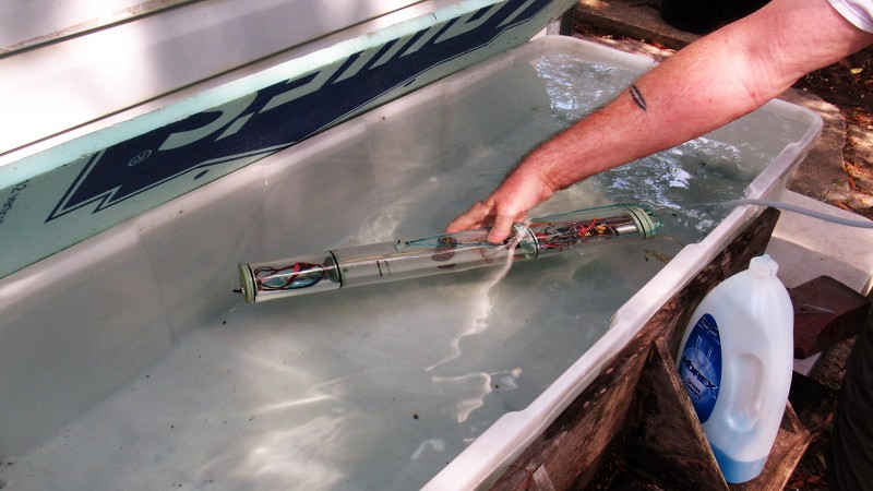
The WTC mechanics all in working order, the last step to re-certification is a leak test. The equalization valve (a common Schrader, tire-valve), projecting from the wet side of the motor-bulkhead, had its core removed and a flexible hose slipped over the valve body. This permitting me to blow air into the cylinder. The WTC was immersed completely in water as I blew into the hose and looked for air-bubbles escaping from the system. Most leaks result from gaps between a seal body and bulkhead -- these are fixed by dabbing a small amount of RTV sealant over the offending area and drawing a suction on the test hose to draw the sealant into the void. A few minutes later the water test is repeated to affirm a watertight system.
And I'm done.
 Who is John Galt?
Comment


Comment