today's work

Collapse
X
 
  • Time
  • Show
Clear All
new posts
  • He Who Shall Not Be Named
    Moderator
    • Aug 2008
    • 12255

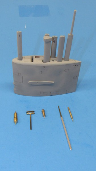
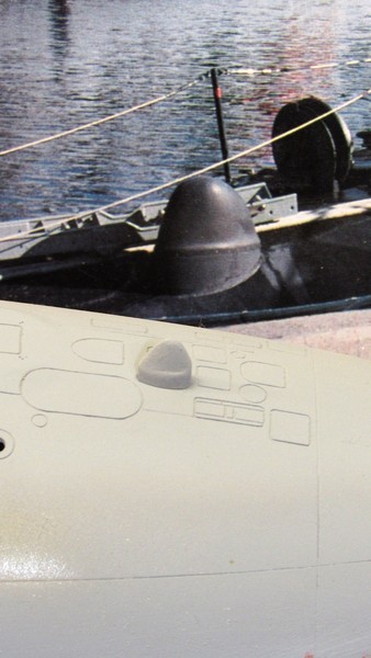
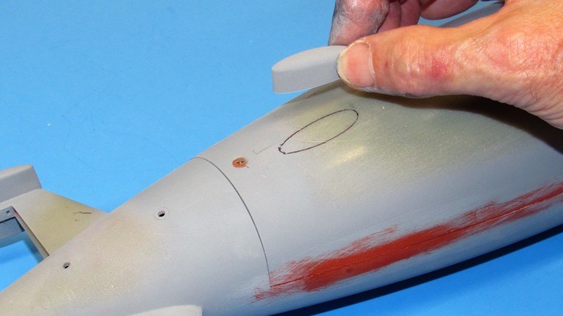
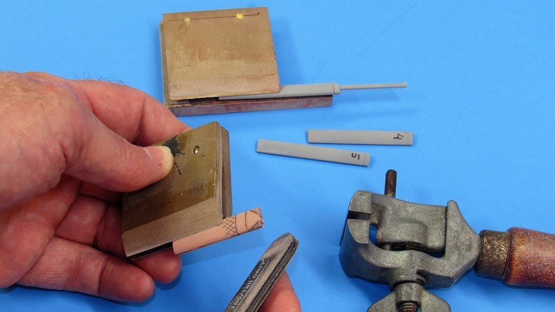
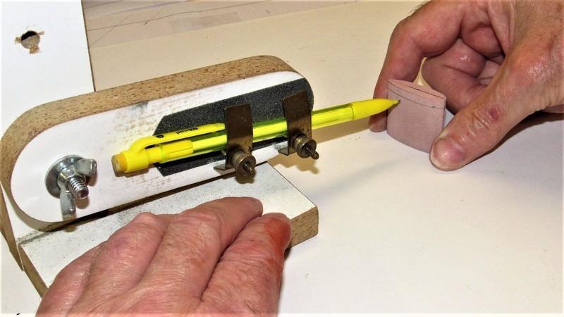
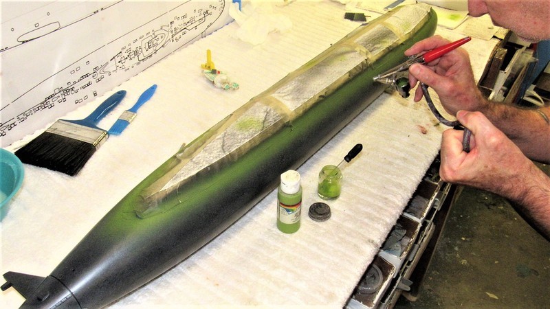
    One last test fit of sail parts to insure proper fit and alignment. From here things are taken apart and the tooling started.


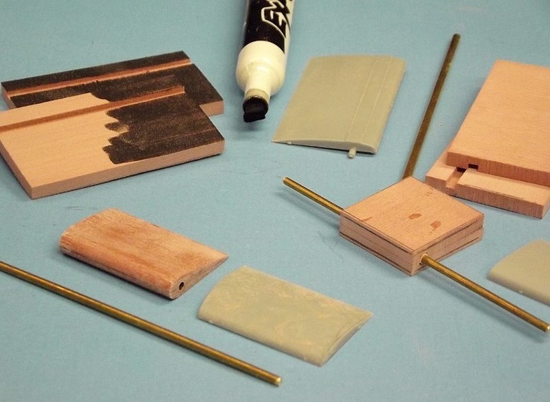
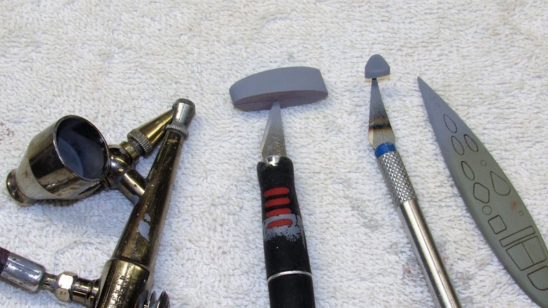
    These masters represent most of the items that will be employed to achieve the tooling from which production parts will be produced to achieve a reasonably detailed sail for the eventual kit.


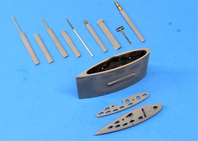
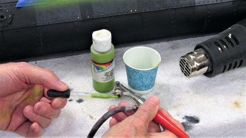
    The scope heads and antennas will be ganged with other small detail items in a disc type centrifugal tool that will be used to produce white-metal production parts for the kit. Those masters in foreground.


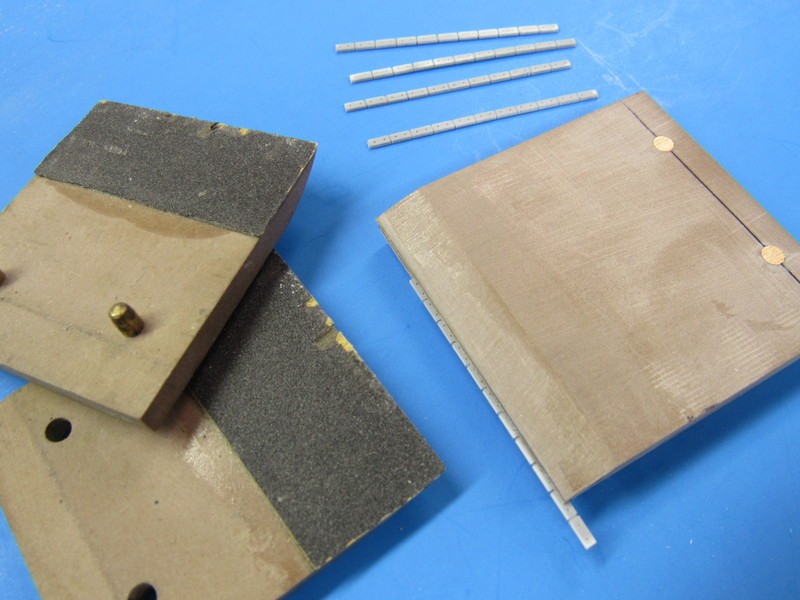
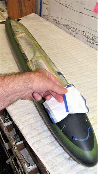
    Three separate rubber tools will be created to form the production parts that make up the STURGEON kits sail. The flask you're familiar with for the sail proper; a two-piece tool for the masts; and a two-piece tool for the sail top -- two version, one representing retracted fairings and one with opening for a display of extended masts; the two sail planes (fairwater planes, for you purists); and the mast internal platform.

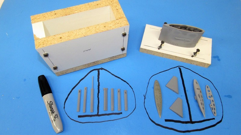
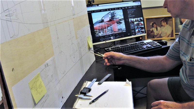
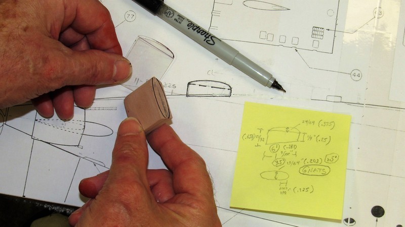
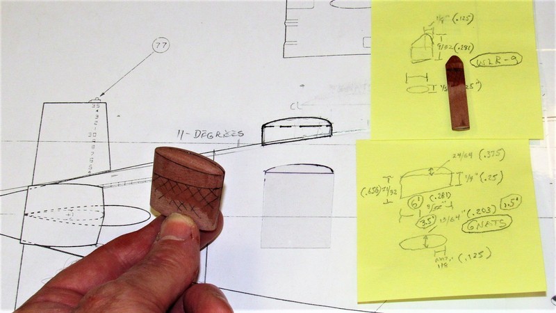
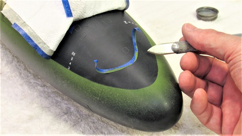
    The inked outline is a study of how to arrange the masters and internal sprue and gate channels. When happy with such an arrangement I cut a piece of shelving 'mold board' to that outline, clay it up and set the masters half-way into the masking clay in preparation for pour of the first half of the rubber tool.


    Who is John Galt?

    Comment

    • He Who Shall Not Be Named
      Moderator
      • Aug 2008
      • 12255


      My Navy buddy, Phil Kordich and I go back a bit. We were navy Divers back in the day. Though we never served together our paths did cross professionally. In the late 80's, shortly after my retirement from the Canoe-Club I introduced Phil (who was and is still into static kit assembly) to the hobby of r/c submarining with a gift of our first commercially available kit, the USS SKIPJACK. Phil was hooked in no-time; we would spend almost every weekend at Mount Trashmore Lake – the most beautiful model boating site this side of the Iron Curtain -- terrorizing the model surface targets driven by other members of our mob, the Elite Fleet.

      Those were the days! This is what it was like to go boating with these ruffian's on a nice summer weekend:


      In later years – soon after the City of Virginia Beach decided that Lake Trashmore was only for looking at, but not for its citizens to use – our club found a home in Norfolk, putting on model boating demonstrations at the Nauticus museum.

      That's Phil to the left driving a surface target as our mutual buddy, Al Lintz, gives chase with a submarine. Blood was let! As it shook out, the well maintained fresh water, cement lined, three-foot deep Koi ponds (the fish never worked out long-term there) are a much better venue for our runs than Lake Trashmore. Suck it, Virginia Beach City Council!

      Al's an interesting bird: As a Gunners Mate he was Coxswain on a Fast-Boat in Vietnam. And today he does duty as the right-seat ballast meat-bag/traveling certified engine-air frame mechanic – riding an honest to God, restored, and flight-worthy de Havilland Mosquito. Part of his day-job now that he's older and slowing down to a more leisurely pace, befitting the stature of an old grump. He's obviously brain-damaged!

      When not restoring classic war-birds at the Pungo hangars he's out there making the air-show rounds here in the States in the above mentioned very fast; high-G pulling; low-to-the-ground; scary airplane held together with pegs, screws, and epoxy glue. But there are perk's to that job: Ever seen and heard two Merlin's coming to life? On a par with the Vulcan 'growl' at run-up. One step removed from sex.

      Al Lintz. From pounding along narrow river paths in a GRP gun-boat to hanging on for dear life aboard a tightly packed plywood attack-pathfinder-spy insertion/retrieval-bomber aircraft. Mr. fast-lane! Oh, and I must mention, Al is a top-notch, old-school, model builder. What's not to hate about this guy?


      In the mid-90's Phil's wife commissioned me to assemble for him a birthday gift – an extensively modified SubTech 1/60 ALBACORE kit. As I had previously had a hand in development of that kit – having acquired a great deal of documentation on that experimental boat, I elected to represent Phil's model as the later variant of that submarine, the phase-4 – his submarine was outfitted with X-tail control surfaces and two concentric, counter-rotating propellers. Before delivering the model (this was over twenty-years ago) I trimmed and worked out the bugs in various outdoor fresh-water basins, and the local dive-center training pool. Note the two counter rotating, concentric propellers. This is the ALBACLORE before they shortened the distance between the two propellers.


      The actual ALBACORE was a commissioned, non-combatant naval submarine used to explore new hull forms, control surfaces, depth-excursion recovery methods and devices, ship control enhancement, speed, exotic battery types, drag reduction through polymer injection, and propulsors. During its career the ALBACORE underwent four significant configuration changes (sources vary as to the exact number), each described as a 'phase'. The model I assembled for Phil represents the most sexy, the phase-4 with the enlarged dorsal anti-roll rudder; X-tail control surfaces, and well distanced coaxial, counter-rotating propellers.


      Note that what I represented was the submarines near to the final propulsor configuration, before the researchers significantly shortened the distance between the two propellers.

      This type propulsor found practical application on the USS JACK, of the THRESHER class. However, they never did work out a reliable shaft-seal system and the boat had to live with a constant flow of leaking water around the shafts. The Navy never revisited the concentric, counter-rotating propulsor again (other than paper studies – hello, ConForm!).

      During the work-up to qualify the model I found it to be frighteningly fast, and scary maneuverable. I loved it! It broke my heart to turn this magnificent beast over to Phil. But he did make good use of it.


      But. Time moves relentlessly by, and friends move away. Such is the case with Phil and his family. They are moving out of Virginia and will homestead in Tennessee. In support of that move Phil asked to borrow my shipping-storage box I built for my 1/60 ALBACORE, phase-2 kit. So -- temporarily taking my model out and placing it in a safe corner -- we transferred his 1/60 ALBACORE, phase-4 kit into it for its journey to Phil's new digs. As his move multiple trips I'll be getting my shipping-storage box in a few weeks time. Nice to know, I have the Groton run coming up the first part of September.

      Just for fun I took these shots of the two models to illustrate the changes the Navy made to the ALBACORE from it's phase-2 to phase-4 configurations. Point of interest: these models were assembled twenty-some years apart. As you can see, Phil is not a practitioner of 'obstacle avoidance'.


      Who is John Galt?

      Comment

      • biggsgolf
        Captain
        • Jan 2020
        • 720

        Thanks for sharing this with us, as we age, so many friends relocate.

        Comment

        • SteveNeill
          Commander
          • Apr 2020
          • 315

          Thanks David! Glad to see you here.

          Comment

          • He Who Shall Not Be Named
            Moderator
            • Aug 2008
            • 12255

            There were two rather distinctive sonar transducer fairings that sat atop some, but not all, STURGEON class boats. For that reason I produce these items as discrete parts, the production parts to be added to the display at the kit-assemblers discretion – depending on what boat of the class, and moment in time, the display represents.

            Unfortunately, the excellent orthographic drawings of the STUGEON I used (I usually mount such working drawings on a bill-board to ease the process of handling and lofting) did not indicate these two fairing in question: the WLR-9 (torpedo detection) forward of the bow marker-buoy; and the GNATS (sonar jammer) well aft, forward of the upper rudder.

            So, I was compelled to post to the various submarine forums I know and requested assistance from anyone in Web-Land. And sure enough, an old buddy popped up, who had access to the real thing, and he supplied me with GNATS and WLR-9 fairing dimensions! An excellent start.

            Then, to further define the shape and location on the hull of these fairings I dragged my drawing into the study, started a search for STURGEON's and found enough photos to fine-tune the shape and location of these items. It was then an easy matter to represent them orthographically onto my working drawings.


            Jumping ahead a little to show you the objective: the nearly completed sonar fairing masters. The forward mounted WLR-9, temporarily mounted on my proof-models bow – in background is a file photo of a real boat outfitted with an actual WLR-9 fairing; and the much larger GNATS fairing back aft.

            (Incidentally, most sailors referred to the WLR-9 as the, 'shark-tooth' for obvious reasons... to the deck-gang it was just another God-damned thing to trip over during the maneuvering watch as you wrestled with retractable cleats, tried to step over open line-lockers, as you and your fellow sweat-hogs wrangled heavy mooring lines).

            The WLR-9 and GNATS masters are in the ruff at this stage but will be refined before they are employed to produce production tooling.


            The GNATS fairing master presented a bit of a problem: its vertical reference plane needing to be parallel with that of the boats, but the fairing is slightly off-set to the starboard side of deck center-line. Careful work with Dremel sanding drum, files, and conformal sanding paper finally got the base of the fairing to make a good fit to the hull, that location denoted by the inked in outline atop the hull.


            As the shark-tooth and GNATS fairings were symmetrical of section I constructed the RenShape blanks as two-piece assemblies – by darkening the face of each half before gluing together I produced an easily observed center-line plane that would never be obliterated no matter how much I cut, filed, and sanded the work to shape.

            I was remiss with my picture taking, I failed to record that process on the masters under discussion here. But, not to fear, the below photo demonstrates the process as applied to a 1/35 Type-23 set of control surface masters. Though not germane to the STURGEON work, but of interest to some, is that by making the master blanks from halves like this you are given the opportunity to mill out, with great precision, channels that later fit control surface operating shafts.

            Note the use of a magic-marker to blacken the inboard face of each blank half. You can also just make out the dark lines that denote the center-line plane of a blank, either in the raw or worked to the desired section – that reference plane NEVER goes away (well... until you hit the work with gray primer, duh!).


            Plan and profile template for the top portion of the GNATS faring. From my photo analysis I determined that the curved upper part of the fairing was the top half of a body-of-revolution, so only one template was required to guide me as I cut the curved portion of the master in plan and profile. Making templates from clear plastic permits you to trace the shape from the drawing onto the template blank without need of lofting measurements with drafting tools, which would be necessary if the template blank was made from an opaque material.


            Once the two sonar fairings were worked to section I then cut them to correct profile with razor saw, sanding block, files and stiff little pieces of #240 sandpaper. Note the selection of hand-vices I employed for this and other STURGEON work.

            Sanding blocks come in many sizes and flavors. This nail-sanding stick for example. You can get these by the bag full at your local beauty supply store. I dare you!


            The hand-made hand-vices are most useful for holding small parts tightly and keep them from flexing as you work with, saw, knife, file and sandpaper.


            Just some of the abrasives on hand for work like this.


            Using Mom's old Jeweler's hand-vice to secure the WLR-9 master as I work it to shape.


            Using a waterline marking tool I denote the base of the upper half of the body-of-revolution.


            First coat of primer to find errors. Those were corrected with sanding/filler and the work primed again. This process repeated till the masters were presentable.


            Who is John Galt?

            Comment

            • Das Boot
              Rear Admiral
              • Dec 2019
              • 1149

              That is going to be nice.
              Of the 40,000 men who served on German submarines, 30,000 never returned.”

              Comment

              • SteveNeill
                Commander
                • Apr 2020
                • 315

                Life makes sense again. Welcome back!

                Comment

                • He Who Shall Not Be Named
                  Moderator
                  • Aug 2008
                  • 12255

                  Originally posted by SteveNeill
                  Life makes sense again. Welcome back!
                  Still here.

                  David
                  Who is John Galt?

                  Comment

                  • CC Clarke
                    Lieutenant Commander
                    • Aug 2020
                    • 239

                    If your reference mat'l doesn't show it, for maximum realism, take it to the next level and add the WLR-9 high freq hydrophone fairing on the top of the sail. It's the little brother, (less than a foot high and maybe 3" wide) of the low-freq 'phone on the bow. There's a second HF fairing on the keel, up forward. (I've yet to see an UW log ever placed on a boat, so an xtra hydrophone on the keel is probably more of a liability than anything else.)

                    Both HF hydrophones offered coverage to detect incoming torpedoes, so it was a good idea to have one covering the top and bottom of the boat. An excellent system built by Norden (the makers of the famous bombsight in WW II.)
                    Last edited by CC Clarke; 08-03-2021, 08:34 PM.

                    Comment

                    • He Who Shall Not Be Named
                      Moderator
                      • Aug 2008
                      • 12255

                      Earlier here I chronicled the repair work I did on my friends 1/72 THRESHER model. The longitudinal edges between the upper and lower hull halves were chipping; and we managed to break off one of the models horizontal stabilizers (I blame the other drivers!).

                      Now, finally, after all the intervening work, I'm completing work on Fred's model. The remaining tasks including a frequency band change, from 75 to 72mHz – to get this model off the more common frequencies used at submarine regattas (not a single model aircraft in attendance. Besides, today's aviator's operate on the 2.4gHz band); and to re-weather the hull to its original look.

                      Here's a shot of Fred's boat before the damage. This is the state of the display we're shooting for after my work. I should have it all wrapped up by the weekend. Done in plenty of time for the next Groton submarine-base all r/c submarine regatta next month.


                      Polk's Seeker-2, 8-channel receiver is physically bigger than more modern receivers, but that's it's only liability. The receiver features a 'synthetic crystal' that can be set – what you see me doing here – to any frequency the transmitter poops out on the assigned band. Once set, the receiver 'remembers' the setting in a non-volatile memory. Big, clunky, old thing!


                      Though an old system, the Polk's Tracker-3 transmitter and companion Seeker-2 receiver were – and are today, if you ask me – the finest r/c system ever devised for the r/c submariners. The transmitter can load and retain settings for 99 models; it has an installed receiver that does a frequency check before transmitting, this to guard against inadvertent frequency conflict between operators; is programmable for every conceivable thing; and above all the transmitter features a 'synthetic' crystal which permits the operator to select any frequency on the band for which the transmitter is intended, be it the 75mHz or 72mHz band.

                      The only requirement for a frequency change being, regardless of system brand, is that the receiver and transmitter are tuned to operate on the same band (a broad selection of discrete frequencies assigned by the FCC – in America the approved bands for r/c vehicles are the 72, 75, 27, 40mHz, and 2.4gHz bands). Most non-2.5gHz systems on these bands require a physical crystal change, and those crystals today are very, very hard to find!


                      In its plastic case the Seeker-2, 8-channel receiver was just a tad too big to fit within the SubDriver. Which compelled me to remove the PCB from its protective case and sheath it within a length of heat-shrink tubing. This reduced the receivers foot-print enough to fit the receiver within the tight confines of the 3.5” diameter SD.


                      It's good practice to insure that the receiver is still alive and well after being heated to tighten up the protective, clear heat-shrink cover. You don't want to install the receiver and only then discover you fried something, necessitating a tear-out and replacement. Just power up the transmitter, receiver, then cycle the testing servo through all eight channel ports as the appropriate transmitter stick, switch, or knob are twiddled.


                      I laid down a strip of masking tape over the top of the receiver, next to the servo pins so I could ink onto the receiver which channel port was what. On the sides of that tape I also indicated polarity of the pins. It's amazing how quickly you forget what goes where, hence my care to make it all painfully obvious when looking at the receiver itself. Once happy that all is right with the world the receiver is connected to the other devices within the SD's motor-bulkhead, and the receiver secured in place with a high-stick servo-tape.


                      You can make out the big size difference between the more modern Wfly 8-channel receiver and the older Polk's Seeker-2 8-channel receiver. Fortunately, when I designed the 3.5” SubDriver device tray I sized the device mounting bulkheads and trays for the largest items then (in the late 90's) on the market. Today, things are much smaller, so are easier to mount. But, with this step back in time I had the available room to fit the old receiver. But only after removing the receiver from its bulky case and wrapping it in heat-shrink.


                      After transferring all the device leads from the Wfly to the Polk's receiver, and before sticking the new receiver into position on its aluminum tray, I did a final systems check to insure I got the right assignments and that there were no problems with the servos, ESC, and low pressure blower motor.

                      Note the use of a zip-cord-and-switch test-cable between battery and motor-bulkhead. This permits off-cylinder test and adjustment. Use of the test-cable permits unobstructed access to all devices mounted onto the motor-bulkhead. It's in this configuration that I set-up the ESC, angle-keeper, and battery-link-monitor (fancy fail-safe). Attempting such steps with the motor-bulkhead half-out of the cylinder, still made up to its power cable and ballast servo, is a nightmare.


                      The only electrical unions between the motor-bulkhead and SD cylinder is the lead between the BLM and ballast tank servo; and the heavy power cable running from the forward battery dry space, forward, through the ballast tank conduit, and finally (me holding it in this shot) made up to the SD devices that require battery power. Good old Dean's connectors made for quick, positive, and high load carrying between battery and SD devices.

                      With only two connectors to deal with, it takes only moments to install/remove the motor-bulkhead and its attached devices from the cylinder. I design and build for simplicity, ease of access, and reliability.

                      See: even that big honking Polk's receiver fits the device tray!


                      Some people make a big deal about charging Lithium-polymer batteries. Which I understand if your a racer and want to get every Erg of energy jammed into the pack. But me, I keep it simple and just jam the current in there through the output wires. Been doing it this way for over a decade and have yet to burn the house down. That said, note the use of a metal plate and fire-brick to keep any conflagration from burning through the table. Never charge when you're out of the room, and have a smoke alarm nearby, tested, and audible. And, to drive home the point, just out of camera frame is a dry-chemical fire extinguisher, with the pin already pulled!

                      I only use the balancing leads to monitor battery voltage when I'm done charging; or mission-checks at the lake to insure I don't run the battery down past the critical voltage. Run town this type battery past the critical low-voltage and it will go all puffy on you. And, yes, I still use puffy batteries! I'm powering up toy submarines not high performance drones!


                      Once I had the THRESHER's SD up and running and talking on the 72mHz band, I prepared the below waterline portions of the hull for weathering, this done with a light wet-sanding with 3000 polishing paper and equivalent sanding sticks.


                      The broad surfaces were easily abraded with a hand held wad of polishing paper. However, in those areas of tight corners and raised items – specifically the tail-cone with its horizontal stabilizers, operating shaft bearing foundations, and zincs – were best worked with very low-grit sanding sticks.

                      Who is John Galt?

                      Comment

                      • He Who Shall Not Be Named
                        Moderator
                        • Aug 2008
                        • 12255

                        Originally posted by rwtdiver
                        I paid close attention to blog entry David! In particular your battery charging station, and the safety precautions that you have taken! Very good sir!! :-))

                        Rob
                        "Firemen can stand the heat"
                        We had to deal with a white-phosphorous fire on the RECOVERY'S fantail following a salvage job -- what a trick-**** element that funky stuff is. We had just hoisted the bird off the bottom, plunked it on the deck and we all broke for mid-rates. Before we could get a mouth-full, off went the GQ alarm, and what do you know, some of the still dripping helicopters on-board flairs caught fire the moment they dried out. Long day. And I've been in a few below-deck firefighting teams, once as Nozzleman. Fire is NOT my friend.

                        Those FORESTALL fire-fighting films and lectures were life savers! And those so trained leave the Navy forever respectful of fire.

                        David
                        Who is John Galt?

                        Comment

                        • Michael McCourt
                          Ensign
                          • Sep 2020
                          • 7

                          what are the fins and conning tower made of in these pictures? is it foam blocks that you cute to shape?

                          Comment

                          • He Who Shall Not Be Named
                            Moderator
                            • Aug 2008
                            • 12255

                            Originally posted by Michael McCourt
                            what are the fins and conning tower made of in these pictures? is it foam blocks that you cute to shape?
                            The fins (control surfaces) are cast resin.

                            Click image for larger version

Name:	IMG_0230.JPG
Views:	220
Size:	41.4 KB
ID:	152125Click image for larger version

Name:	IMG_0227.JPG
Views:	212
Size:	29.6 KB
ID:	152126

                            The conning tower (sail) is GRP and resin.

                            Click image for larger version

Name:	001.JPG
Views:	232
Size:	48.4 KB
ID:	152123Click image for larger version

Name:	006.JPG
Views:	220
Size:	55.9 KB
ID:	152124
                            Who is John Galt?

                            Comment

                            • He Who Shall Not Be Named
                              Moderator
                              • Aug 2008
                              • 12255

                              OK! All the prep-work done on Fred's 1/72 THRESHER. Time to lay down the hull weathering. Which will have to match that of the original finish on the upper rudder and two stern planes. As it was well over ten years ago I did the original weathering on this model submarine, but now compelled to match it in 'color' and density. All representing the random bleached out 'patchiness' of a structure that has been in salt water for an extended period of time. Since memory fades with time, I thought it prudent to practice the nearly forgotten the subtle points of that process on a test article.

                              And here it is, the next project on my to-do list! But not just yet. First, it has to do some dirty work for me: I'm temporarily turning a failed HUNLEY r/c submarine model hull into a painting and weathering test article.

                              ...Hope the client isn't reading this!

                              As I would be experimenting with variations to the weathering (type of liquid mask, density of over-coat, and type tool used to apply the liquid mask and other weathering mediums), I used masking tape to section off several portions of the test article. Each test section labeled and process notes taken so when I stumbled upon the techniques that produced the best match to the THRESHER's original weathering (the stern planes and rudders) I could go to those notes, replicate consumables and techniques, and jump straight to the THRESHER hull weathering job without fear of screwing it up.

                              Measure twice. Cut once!


                              First I experimented with polyvinyl alcohol (PVC), then tooth-paste. The tooth-paste won the contest. The liquid mask application is with a semi-stiff brush, delivering the liquid mask by a stippling motion of the brush; stabs, not sweeps.

                              The way I achieve a 'splotchy' look to a surface is to apply over the base color random splotches (is that a word?) of a water-soluble liquid masking that, when dry, will prevent over-coat(s) from discoloring the underlying color. The overcoat is a tan that is well cut with clear acrylic, and further reduced with a good helping of water. I don't want an opaque over-coat, I want a semi-opaque over-coat.


                              After the overcoat dries on the work (a heat-gun speeds things up considerably) a wet rag dissolves and pulls away the mask, revealing the splotchy black, not-so-black look. It took several different tries on the test article, but I eventually replicated the original look of below waterline weathering. My gauge, or reference item, was the old lower rudder still in its original weathered state.


                              Getting the desired weathering result on the test article I shifted work to the THRESHER model itself. I used a small stippling brush. As I did a section of masking I would stop and dry it out with the hot-air gun and move onto the next patch. Doing so kept me from smearing the masking agent as I handled the model.

                              The liquid mask is nothing more than gummy tooth-paste thinned with water and transferred to the work with a brush. Stippling is a stabbing action with the brush, not the usual back-and-forth sweeps over the work. This produces the varied pattern of masked, and unmasked portions of the hull.


                              However, that cheesy little brush was taking all day to lay down the tooth-paste liquid masks, so I shifted to the big-gun: a nasty four-inch, warn-out Walmart house-painting brush I dug out of the shed. NOW WE'RE TALK'N! Some times the gnarly tools are the right tools!


                              All the masking dry I sprayed on a heavy 'mist coating' of a tan color cut heavily with an acrylic clear-coat. You just can't water down the pigment -- you still need the adhesive binders of the resin (which incidentally classifies the paints chemistry) to make the paint stick well. Too low the binder content, the lower the paints adhesion to the work, the easier it is to scratch and rub the dried paint off the model through handling and later masking operation. You just can't thin (in this case water) the paint to get a semi-opaque coat, you have to achieve that objective by adding a clear resin binder; a clear-coat.


                              Several coats of this light colored, semi-opaque paint went down, using the heat-gun between coats to insure things are dry before applying more paint. Fail to do this and you get beading, orange-peel, and possibly even the dreaded 'fish-eye' spots in the paint. Water soluble paints are intolerant of heavy wet build-ups. The heat-gun makes the work go as fast as you can swing the air-brush and gun. I hate waiting for paint to dry!


                              And, finally, the green colored 'marine growth' you typically see just below the submarines waterline. In drydock this quickly dies and bleaches out to a light tan and/or gray. And STINKS!!!!!

                              The above waterline portions of the hull had been masked off for months, so I could jump right in with the green loaded air-brush.

                              Hobby-shop acrylic paints are stupid-expensive. You can buy the same crap at Walmart for a fraction of the price! Besides, quality here is wasted as the entire hull will later be over-coated with an industrial quality flattened clear-coat to protect and even out all the applied paint and weathering mediums.

                              (Hobby-shops used to be fun places. Not any more. What few that still stand are franchised big-boy-toy-stores with RTR crap in big, fancy boxes. Most counter-people are face pierced and tattooed, slobbering idiots. I long for the old mom-and-pop shop where you could actually buy building supplies and get useful advice from the guys behind the counter.)


                              Starting to remove the masking so I could get on with the next operation: blending in some white Artist oil paint just below the waterline to represent the dead and bleached marine growth that accumulates at the waters edge when the boat is floating in the water pier-side. The scum-line.


                              After laying down the scum-line I'll reinstate the bow draft numbers below the waterline, do a little touch-up work, paint the cathodic protection zincs back aft a light gray and then, finally, blast the model with a near bullet-proof, well flattened DuPont ChromaClear protective coat, and the display will be finished (again).


                              I laid-down the feathered green marine growth on the test article. Note that for small volume air-brush paint jobs you can dispense with both the paint bottle and paint-cup and just put a few drops (which is all that was needed for this job) into the air-brushes needle directly. Makes later clean-up of the air-brush a much easier, quicker job.


                              Since Artist's oil paints can be smeared to blend in with the other work, that was the choice of paint selected to represent the scum-line. A small chisel-brush was the weapon of choice here. A small amount of paint was deposited on a paper palette and the brush lightly loaded, then carefully run along the edge were the green meets the black. A paper towel is then used to smudge the white paint downward, feathering it slightly into the green paint.


                              Using the original weathering of the upper rudder to check likeness of results between it and the test article. Good enough! Time to take the work to the model.


                              And here you go.


                              Who is John Galt?

                              Comment

                              • SteveNeill
                                Commander
                                • Apr 2020
                                • 315

                                Masterful!

                                Comment

                                Working...