-
Who is John Galt? -
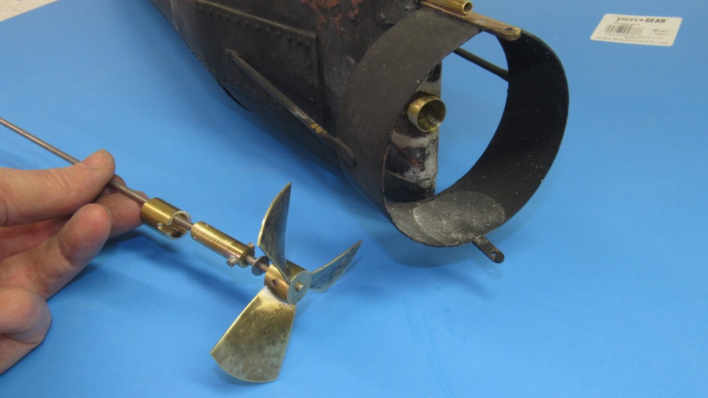
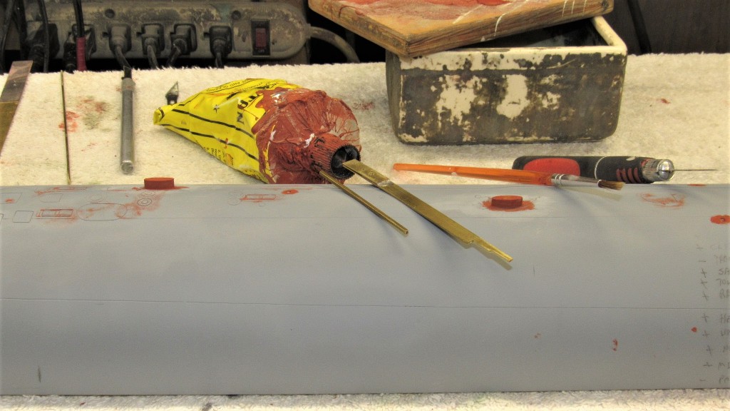
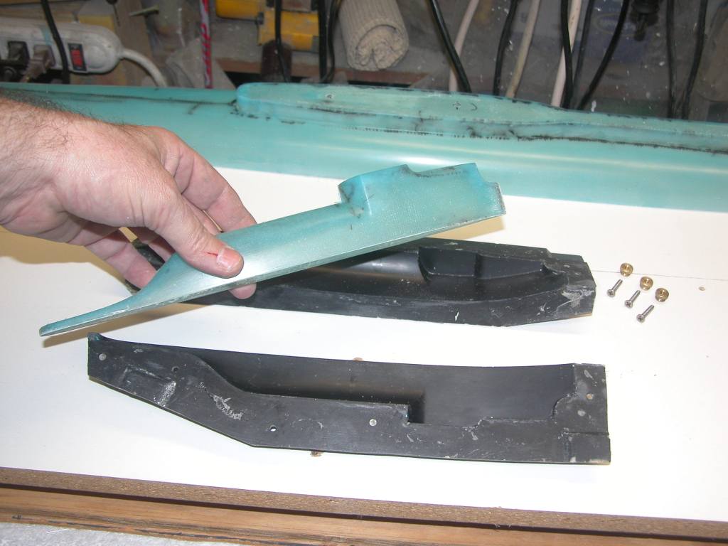
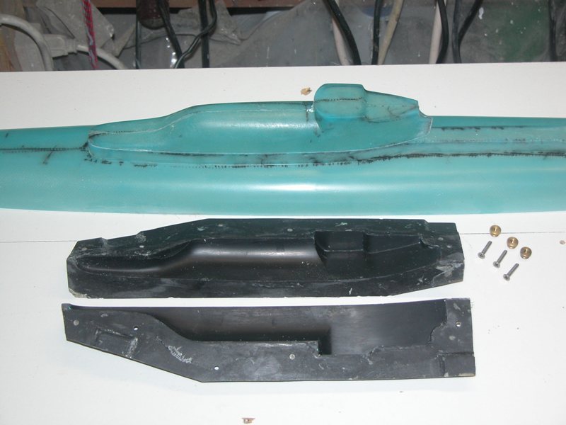
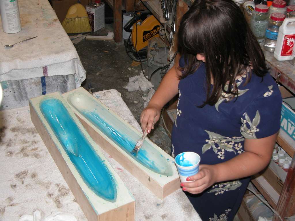
Got the propeller done and started to back-fit the proper torque-rod type rudder actuator -- got ride of the two pushrod-bell crank arrangement (an artifact from bum documentation that originated with one of the boats builders well after the event.
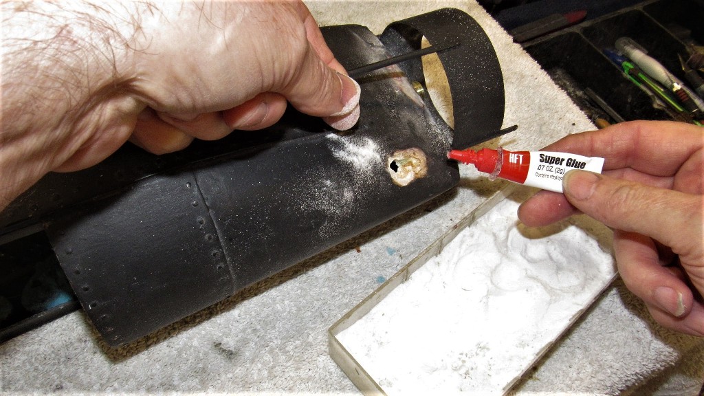
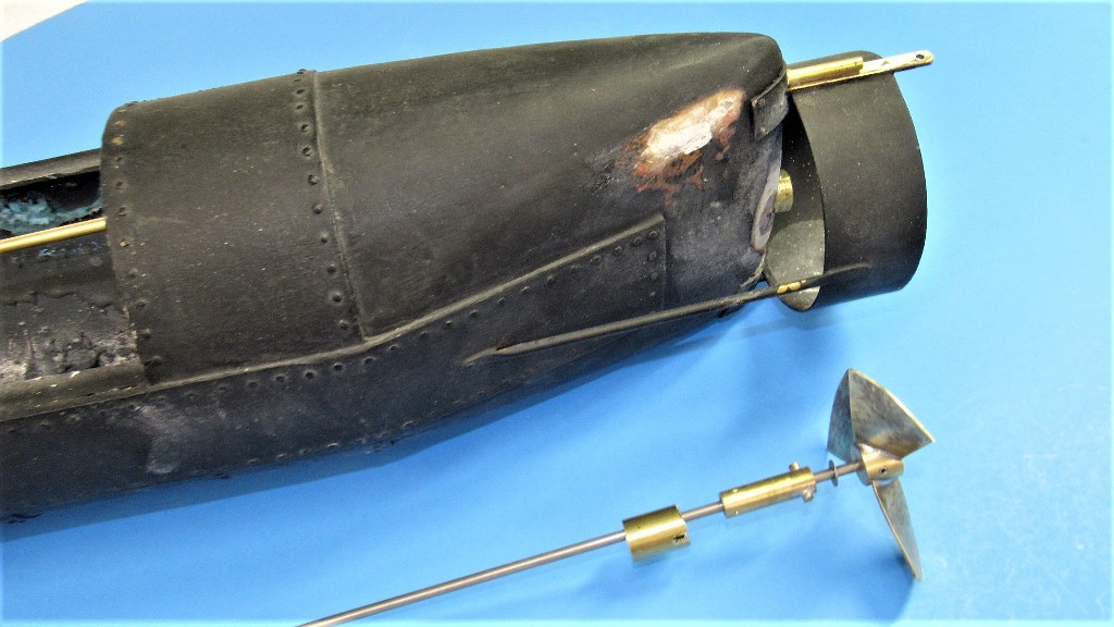
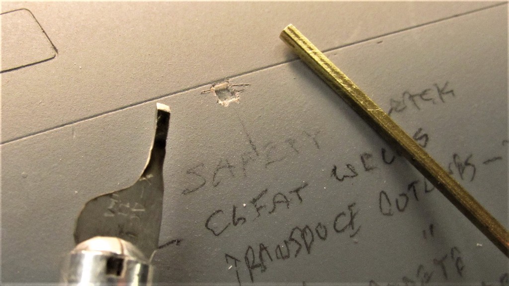
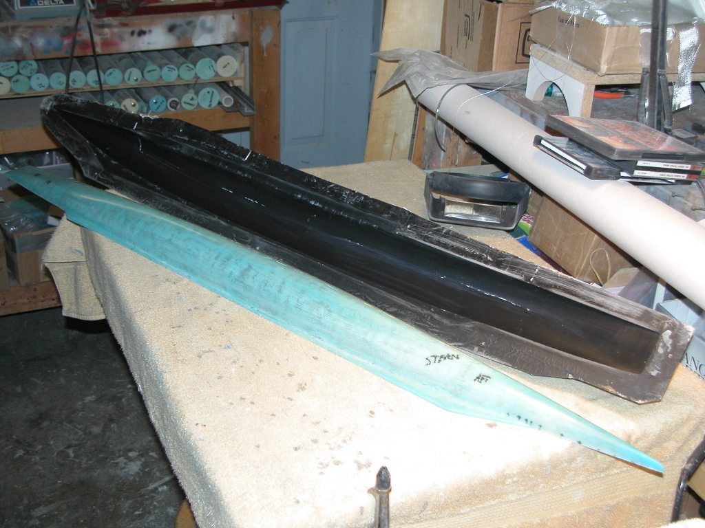
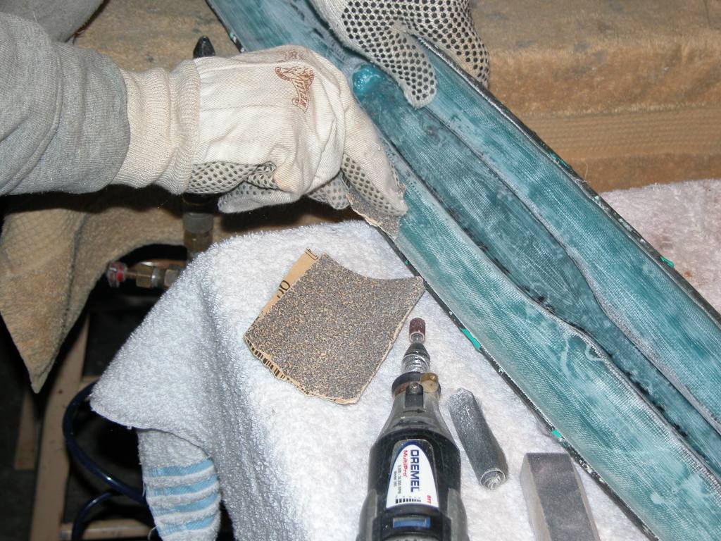
The rip-out of the two pushrods produced holes at the upper stern. These had to be filled, and most of that work was done with CA and baking soda.
The operation starts with a back-up of the hole from the inside -- wax paper if you want to be neat. A paper towel if you don't give a damn. While holding the back-up tight to block the hole from the inside, some baking soda is sprinkled on and thin formula CA applied, which instantly hardens. Repeat till the mass is higher than the surrounding structure. At that point the back-up is pulled out.
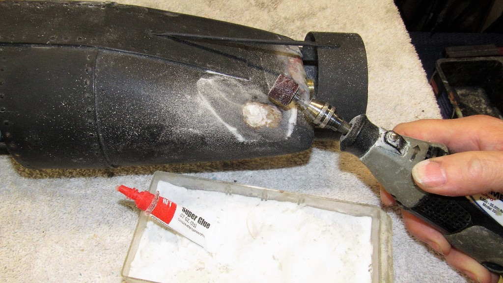
The mass is then ground down with a sanding drum followed by a course file, then sandpaper.
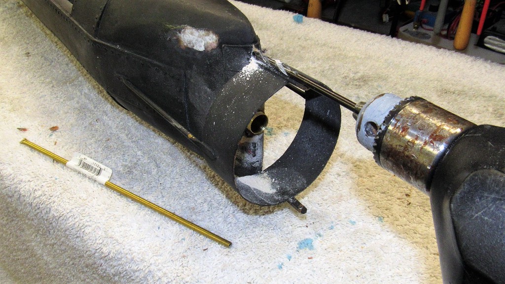
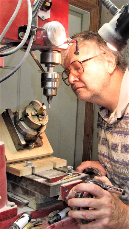
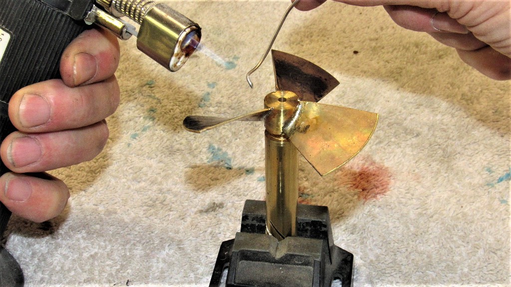
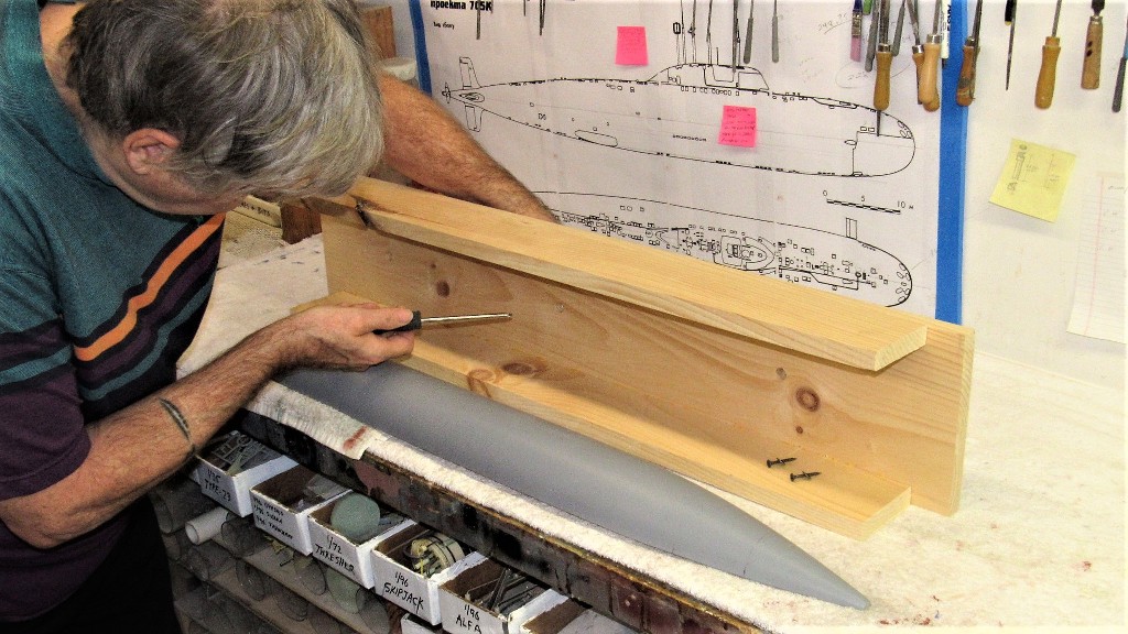
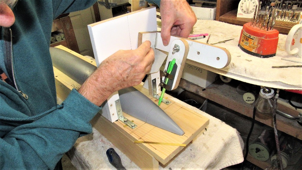
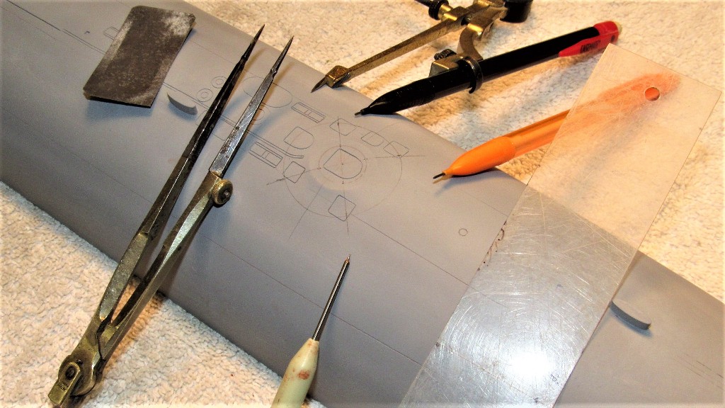
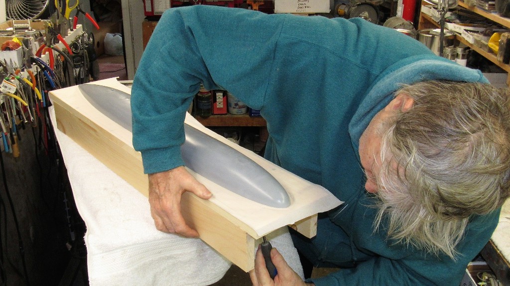
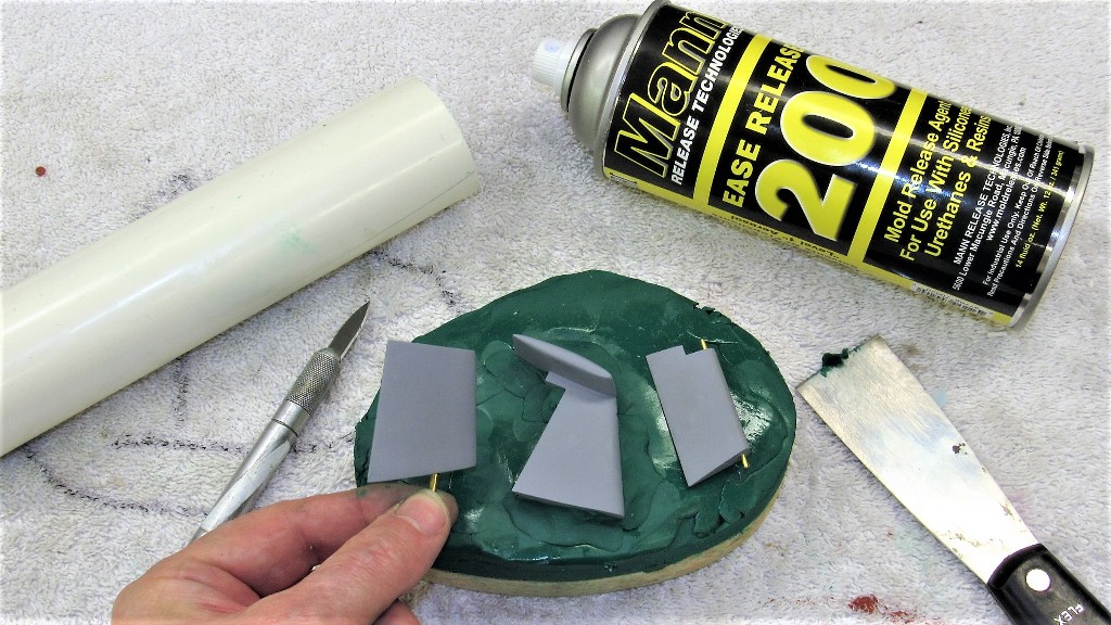
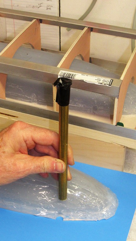
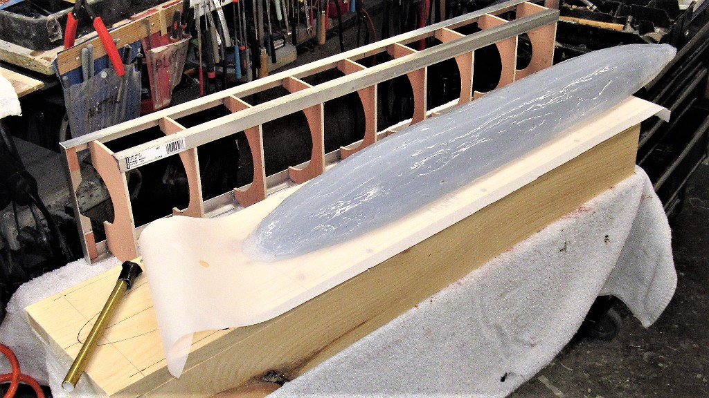
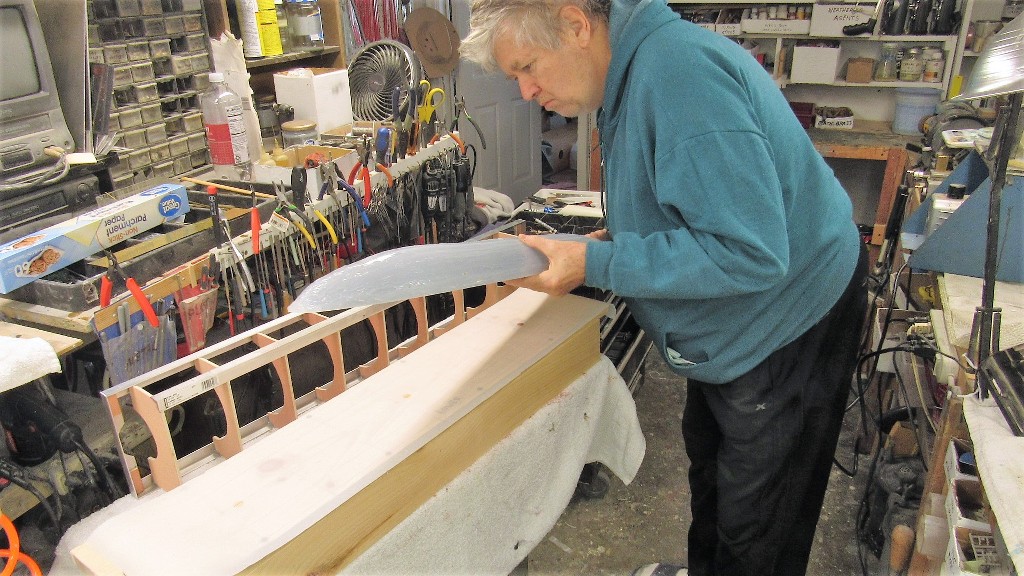
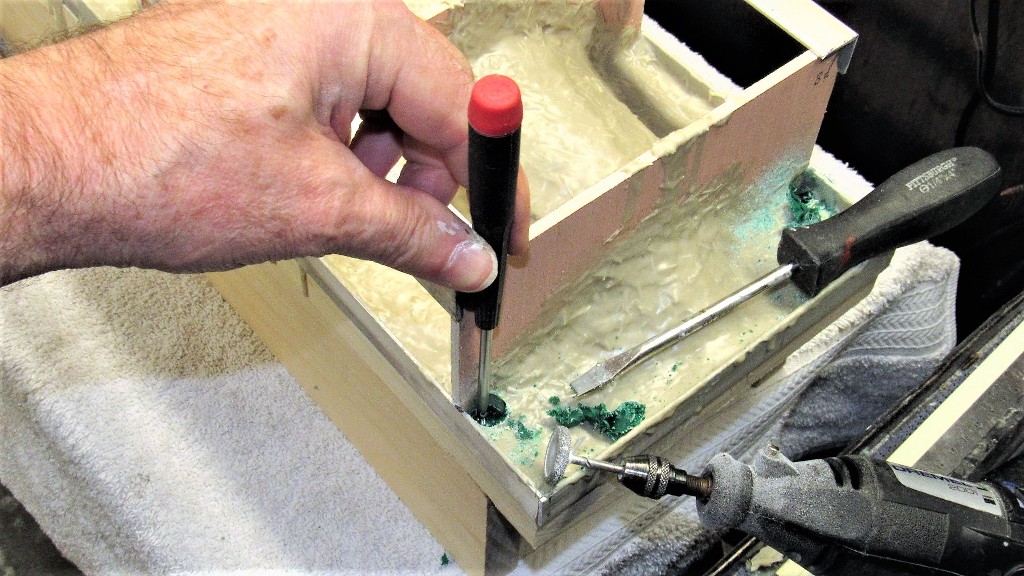
Drilling a hole to accept the rudder torque rod tube.
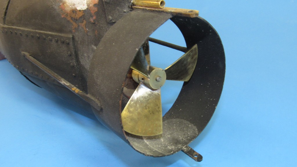
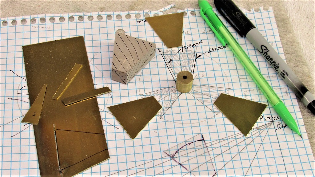
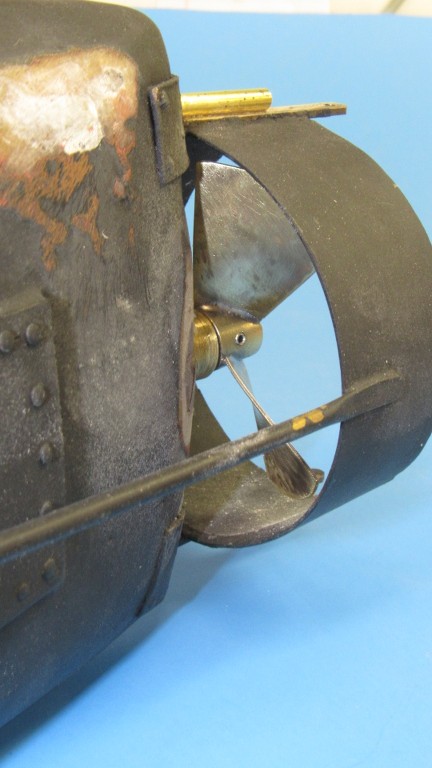
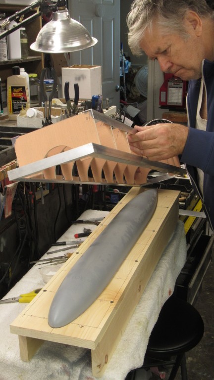
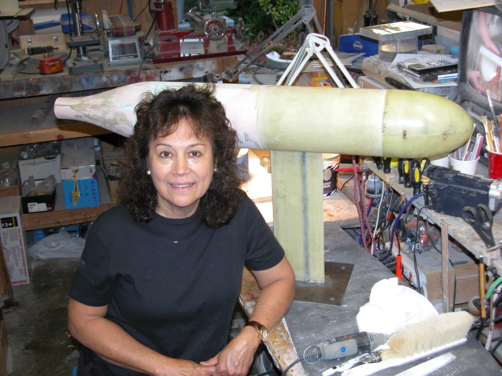
I'm jumping ahead a bit to show you the end-game: the completed propeller and pitch gimbal, all installed. The objective is to achieve positive control of the boats pitch-angle while submerged through the use of active thrust vectoring -- tilting the propeller up and down will produce the torque needed to keep the boat on a near zero bubble angle.
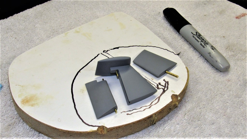
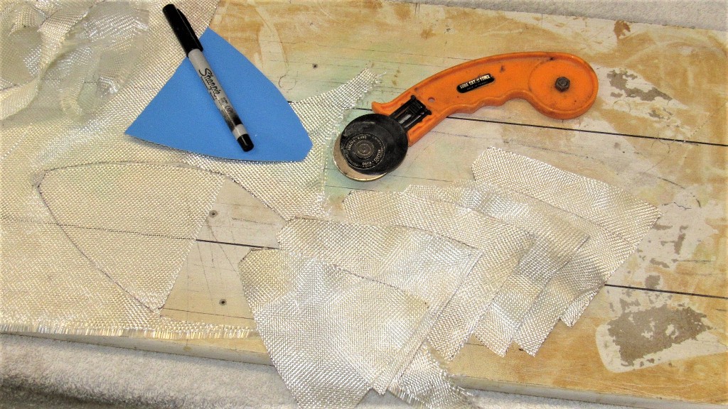
From .030" thick sheet brass I cut out three propeller blade blanks. Then, from dense RenShape, I carved out a blade pitch mandrel that would be used to form the annealed blades to the correct helical twist demanded by the blade-chart.
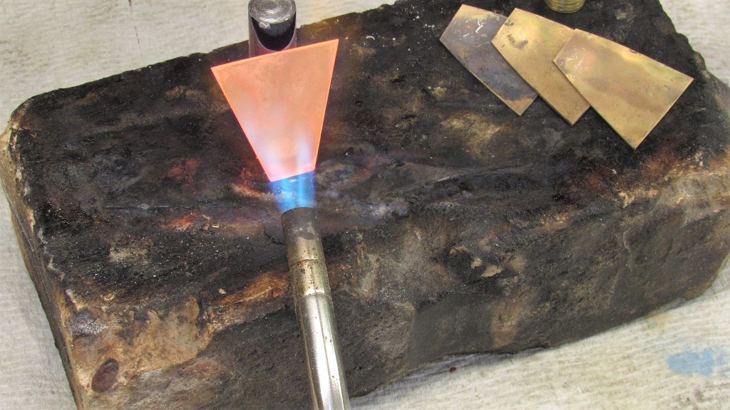
The cartridge brass is much too stiff to bend easily, so it it taken to a red heat and allowed to cool back to room temperature without quenching. The softened propeller blades are now malleable enough to be easily bent to the required twist by hand and light hammering over the mandrel. (if you look carefully you can just make out Exeter's image on the view screen as it cools... joking!).
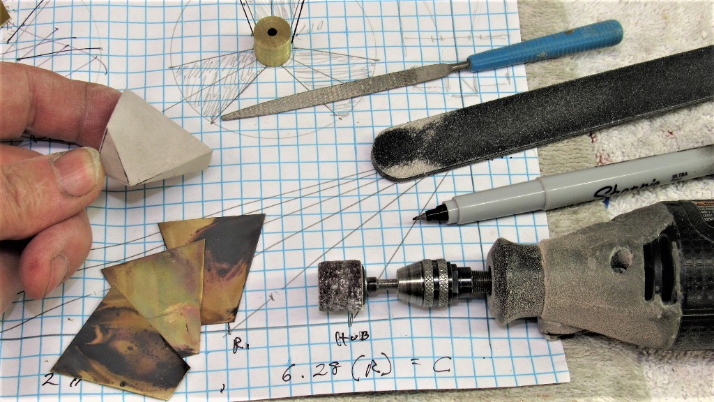
Here I've ground, filed, and sanded the helical twist into the blade forming mandrel. The oxidation on the blade blanks is a consequence of the heat treatment and is later abraded away after the blades are formed, and soldered to their solid brass hub.
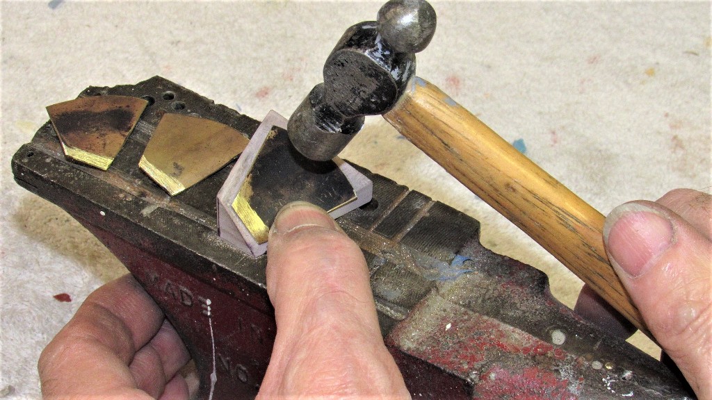
Most twisting of the blades was done between thumbs and forefingers. The final work was done with repeated light hammer blows with the work sitting on the face of the mandrel. The mandrel was temporarily glued atop an anvil. The constant hammering 'work hardened' the blades, making them stiff enough to handle and assemble without fear of accidently bending them out of shape.
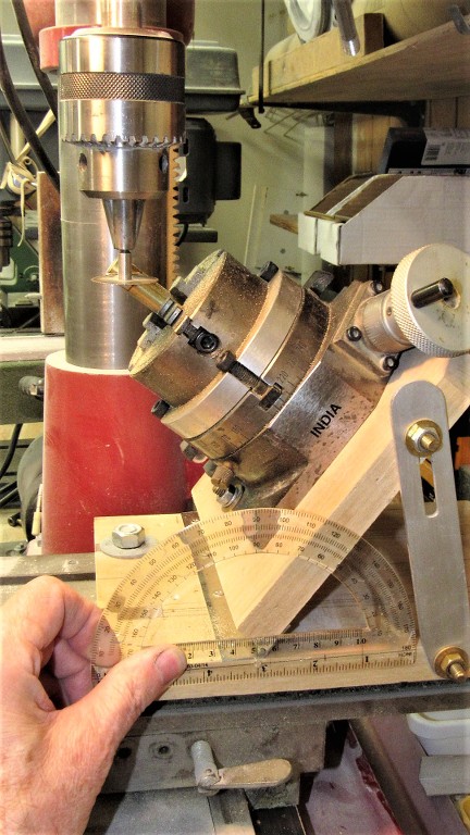
Three slits were cut into the solid brass hub to receive the propeller blades. A rotary table, angled to the saw to produce the correct blade-hub interface slits. As the rotary table is indexed it was an easy matter to dial in the three equally spaced slits.
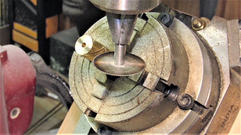
I love my cheap-ass Chinese milling machine, but sometimes (like here) I wish I had sprung for a proper Bridgeport machine with the ability to tilt the spindle-head instead of having to jury-rig this Rube Goldberg fixture to angle the rotary table to the saw. Oh, well.
From the blade-chart I was informed that the angle at the hub where the root of the blades fit is 55-degrees. So be it -- I hear and obey!
The blade roots were a tight fit to the hub slits so there was no need for a holding fixture as the blades were soldered in place. Friction is our friend! Here I'm slathering on some acid flux to insure a nice clean, strong wetting of the metal as the molten solder is applied.
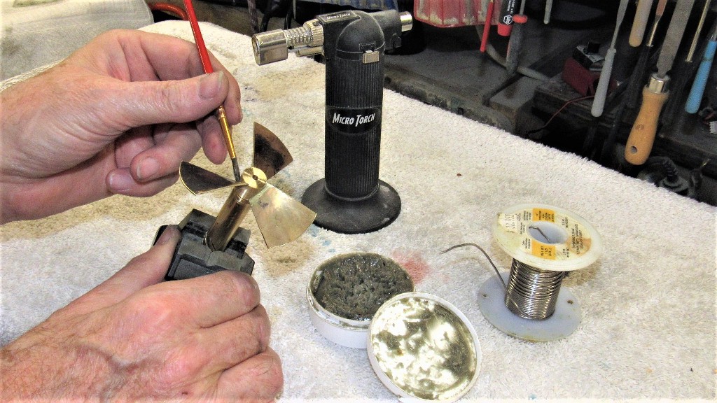
60-40 solder is fine for this kind of work -- plenty of adhesive area, buttressed with heavy fillets. The soldering operation only took seconds to perform. Soldering is adhesion, not welding; it's glue, boy's and girls.
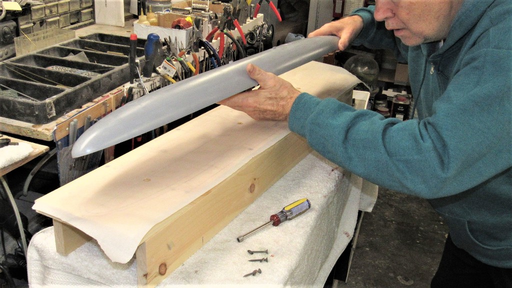
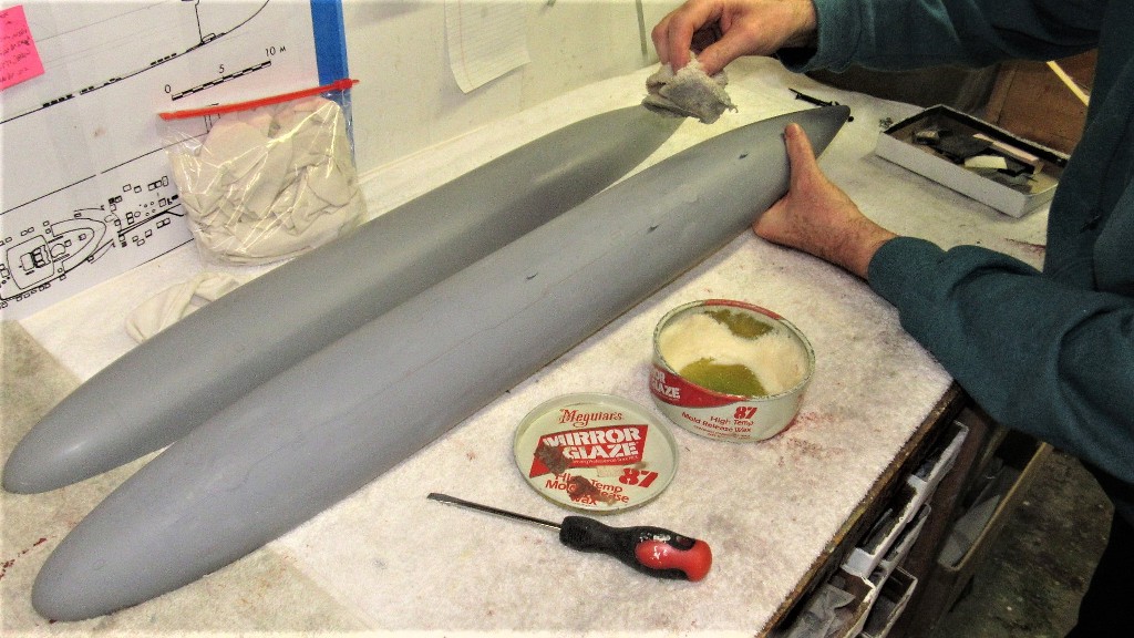
Files, sandpaper, and a rotary wire brush cleaned up the assembled propeller.
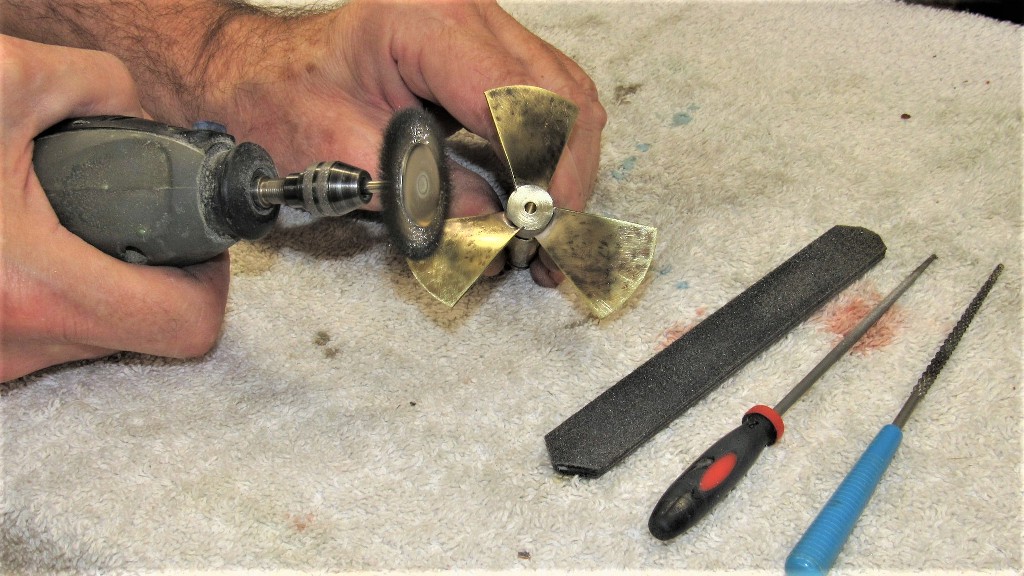
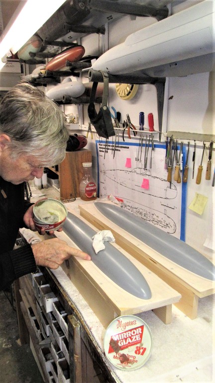
And the completed propeller assembly.
Who is John Galt?Comment
-
David,
Didn't you have a dedicated thread on propeller making?Make it simple, make strong, make it work!Comment
-
Redundant? No.
I'm sure some of the newcomers would like to know how to fabricate their own prop from scratch. As you said some of the good stuffs tend to get buried under. Hope Bob can find it and place it in a dedicated archive.
Redundant? No....Make it simple, make strong, make it work!Comment
-
That prop is BEAUTIFUL...absolutely spot-onA man of true Frankenstinean proportions!!Comment
-
Fantastic work on the new Hunley propeller and gimbal!
Here’s a link to more of your propeller work from the older type XXIII build.
Not sure if this is what you guys are referring to, but a great informative build thread nonetheless.
NickComment
-
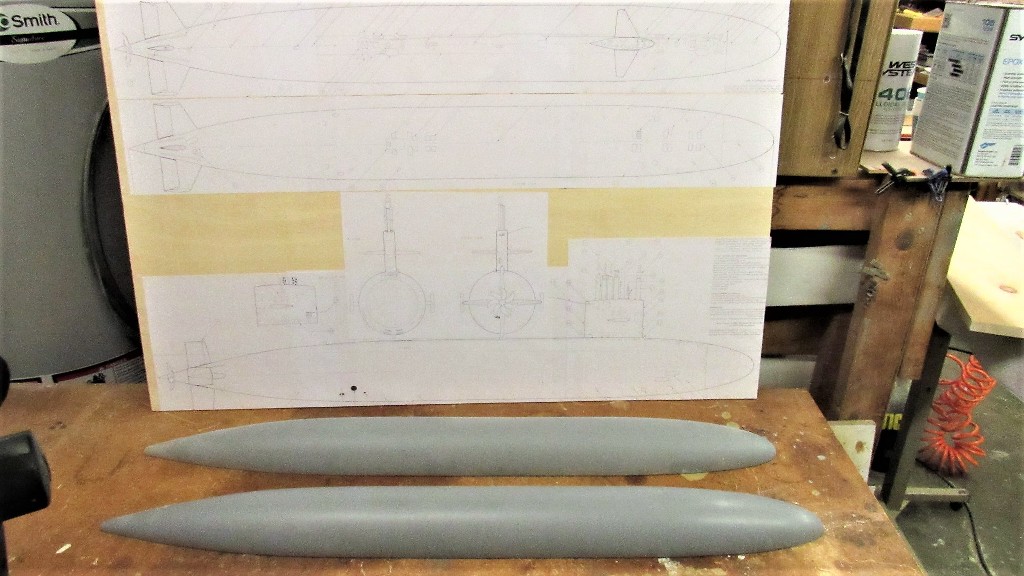
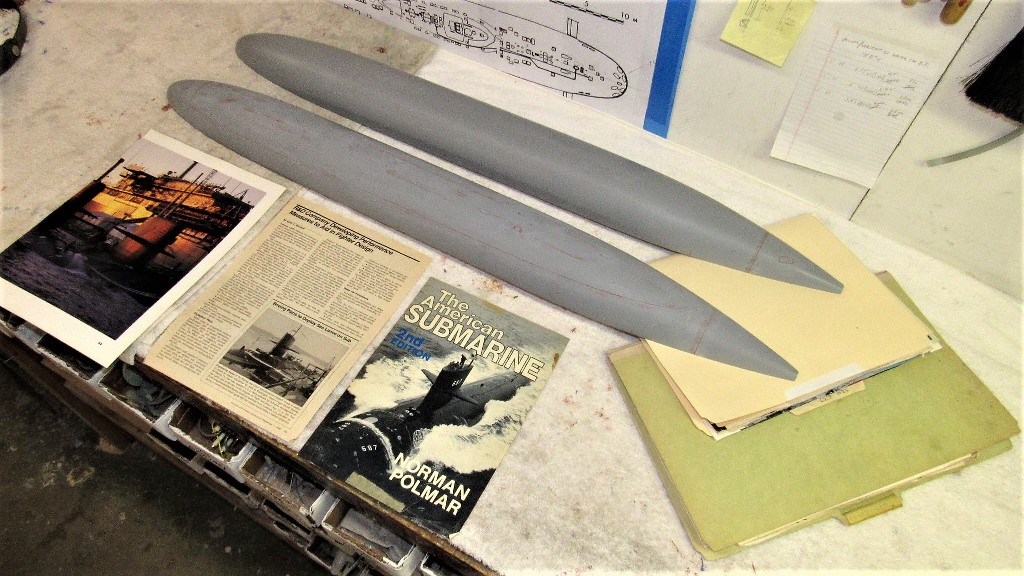
I'm currently engaged in creation of tooling that will be used to produce GRP (fiberglass) hull and resin and metal parts of a 1/96 scale kit of the American STURGEON class attack submarine. Most of the masters I'm handling here were created by Matthew Thor who sold them to Nautilus Drydocks, an outfit I've been affiliated with for a number of years now.
Details concerning the STURGEON and the other thirty-six boats of the class can be found here: Sturgeon-class submarine - Wikipedia
The quality of the masters I received were, for the most part, exceptional in regards to their scale fidelity and craftsmanship; very, very good work.
However, there were a few problem areas that had to be addressed before using them to produce the tooling. As research is everything when dealing with scale models, I took pains to study my files and external sources – the objective was to create masters that would depict the first 'short hull' boats of the class. I leave it to future customers of the kit to make the appropriate modifications needed to configure their model to suit the characteristics of a specific boat they wish to represent in miniature. I only supply the canvas, not the paint.
The principle document I used to further detail the STURGEON masters was a 1/96 scale, five-view orthographic drawing produced by the famed Canadian r/c submariner, Greg Sharpe. His work lofted off official documents. I consider them source material. Someone correct me... I dare you!
Buttressing the drawings were hundreds of photos and other documents I've been collecting the last forty years.
There are two schools of thought as to how tooling intended for GRP production should be made.
One is the 'hard-shell' type mold – typically a stiff GRP lay-up over the master. This type has the virtue of being simple and cheap to produce. The drawback to this type tool is the need to avoid deep draft items; the master has to be compromised as to depth of engraved lines in order to prevent entrapment of the master (and later the GRP part produced) within the tool that gave it form.
Any significant depth of engravings invariably leads to tool damage during the extraction process. You just can't get the level of engraved and/or high relief detailing into a hard-shell tool than you can with a rubber tool. Also, the hard-shell tool is most unforgiving if you fail to correctly apply the correct type mold-release system between lay-up cycles – get it wrong and you trash the tool!
The resulting GRP hull part produced in the hard-shell tool will capture engraved lines, yes, but by necessity the depth of those engraved lines must be shallow and unreasonably wide. The result is engraved detail that is not deep or narrow enough to throw significantly stark shadows, greatly reducing the visual impact of the engravings.
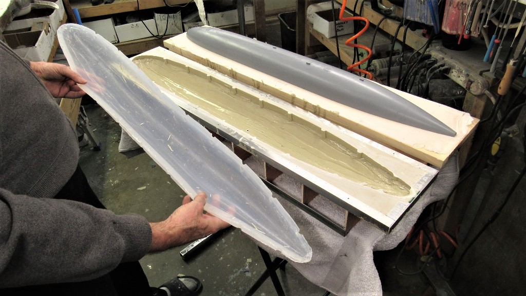
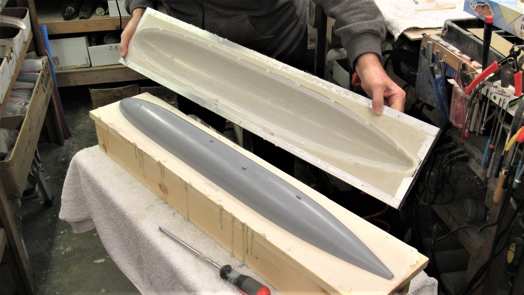
The preferred tool is of the compound type, made up of two elements: a flexible rubber glove-mold, backed by a stiff mother-mold. This type, owing to the flexible nature of the rubber glove has no problem separating from the master and later production parts regardless of draft depth or angle – this type tool will easily pull away from parts of negative draft without damage or wear. Such as this 1/96 THRESHER hull tool.
Once the GRP has been laid up in the rubber glove, the glove is pulled away from its backing mother-mold and peeled – like a glove – away from the GRP part. No matter the engraved or high-relief items unique to the subject, the glove nor the part is damaged during the de-molding process. Pretty damned slick!
All that needs to be done is to re-seat the glove into the mother-mold, spray on a few coats of poly vinyl alcohol, and you're ready to start another GRP lay-up. No waxing, no buffing, no bull-****.
The result of the mother-glove type tool are deep, crisp, narrow engravings. The bow of this completed 1/96 THRESHER class model, formed in such a tool, so demonstrates. Compare the engravings on this model to those on the hull produced in a hard-shell type tool. A world of difference.
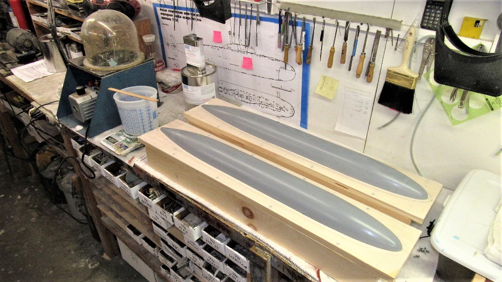
The two STURGEON hull masters – an upper half, and a lower half – were mounted on a mold-board. The flat face of the mold-board would later form the parting flange shared by the hard and rubber faces of the compound tool. One tool for the upper hull, one tool for the lower hull.
Each hull master was secured to its mold-board with the aid of three deck-screws passed up through the bottom of the mold-board.
Most of the STURGEON hull tooling work involves building the support structure for the eventual mother-mold element of the tool. These structures, called 'egg-crating', provide a stable support for and convenient table upon which the inverted tools cavity is accessed for part glass lay-up. The egg-crating only goes onto the mold board after the rubber glove has been built up over the hull master and over that the first layers of mother-mold tooling resin applied. Eventually the tooling resin will bond to the ribs of the egg-crate forming the ridgid and easy to handle assembly.
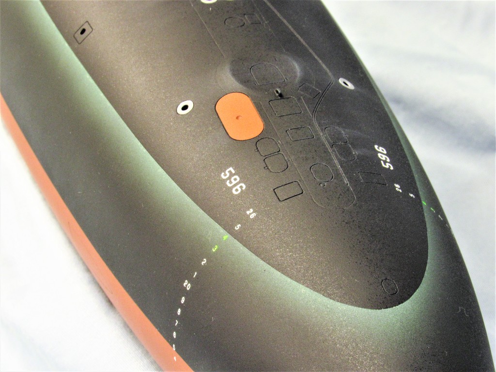
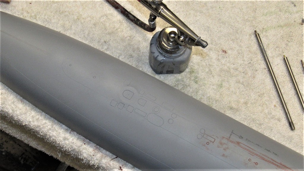
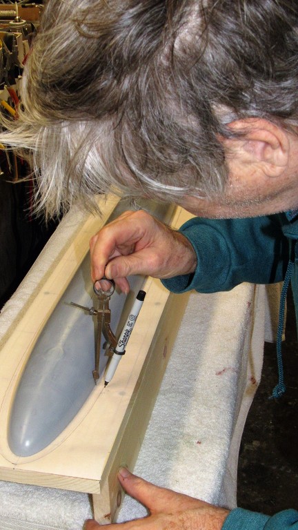
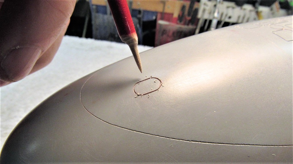
Enhancement of the hull masters included inclusion of a radial engraved line near the stern. This will denote, on the GRP hull parts, where to cut away the end of the assembled hull to make way for a hollow cast resin stern cone that will come complete with attached horizontal stabilizers, stern tube and bearing, and rudder and stern plane interconnecting yokes. Good kit engineering strives to produce a product any mouth-breathing idiot can assemble with the minimum of fuss.
A vertical fence was temporarily screwed in place over the mold board to permit use of a waterline marking tool to lay off a radial pencil line onto the stern of a master. I would later remove the master from the mold-board and with careful use of a razor saw I would engrave a very shallow, narrow cheat-line.
The one major fault with the Thor STURGEON hull master we received (I suspect there are more than one set of 'masters' out there) was the height of the two escape trunk hatch 'flats'. Instead of the plane of the flat being flush with the top of the hull the flats stood .040” over deck level. That had to be fixed. Fortunately this portion of the master was a cylinder of easily ground, scribed and filed plastic rod. After that work the deck hatch outline was re-scribed
Once the two escape trunk flats had been taken to deck level I ran a length of pencil 'lead' over the hull – the fragile lead strengthened by gluing it to a scrap piece of plastic sheet that also served as a handle. Resting a portion of the lead on the circular rim of a flat I circled it around to that the outboard portion of lead contacted the hull, denoting where the eventual fairing between flat and hull took place.
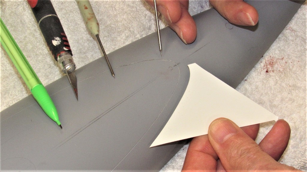
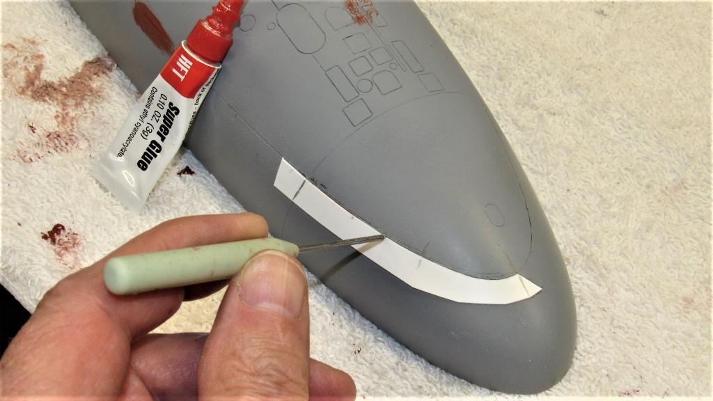
I set about the work of fairing the outboard areas between circular flat and gentile compound curve of the hull. I'm showing the work at the bow, but the same job had to be performed as I worked the engine room escape trunk hatch flat as well.
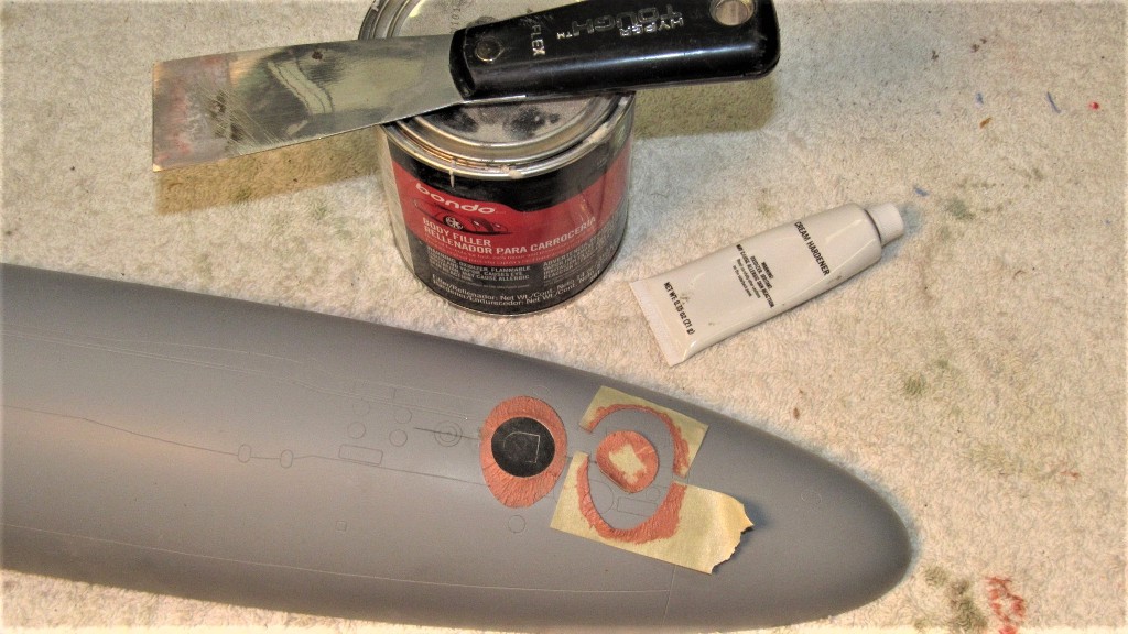
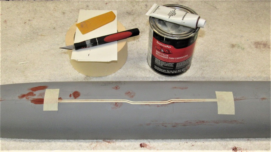
A mask was prepared to confine the Bondo to only those ares on the hull where there would be a fairing. Those masks went a long way in reducing the work involved in filing and sanding the Bondo to shape.
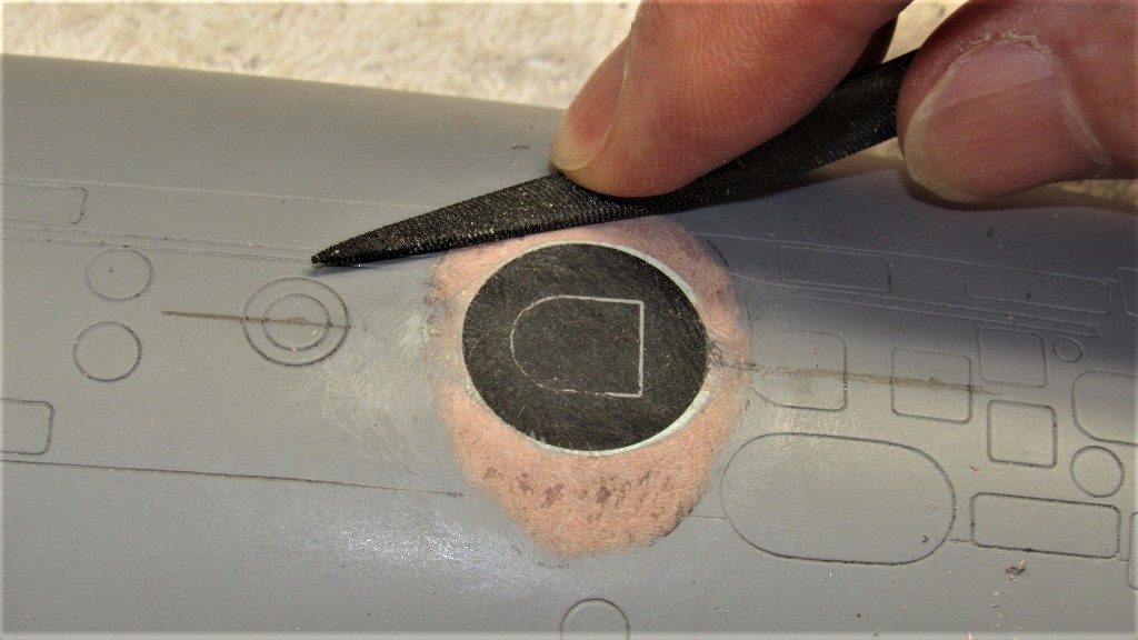
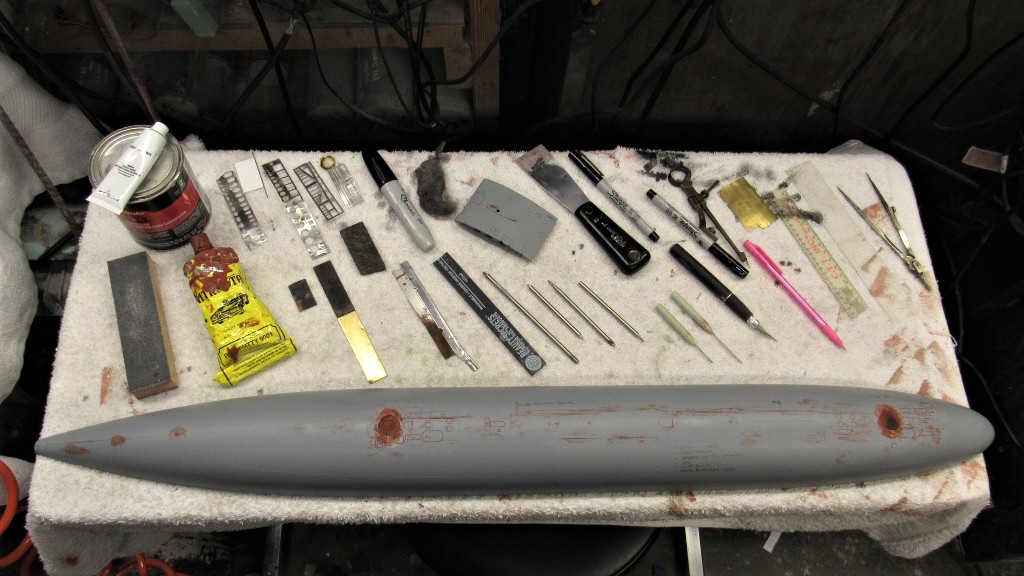
The second major chore was to deepen – and in only a few instances, correct – engraved lines that denoted access hatches, line lockers, capstans, main ballast tank vents, salvage plates, buoy markers, reversible cleats, bull-nose, torpedo tube shutters, ballast tank flood-drains, anchor, main and auxiliary sea water penetrations; and portions of safety-track.
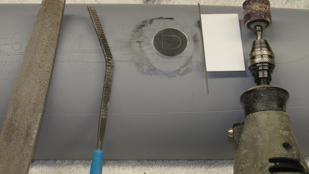
What a job the engraving enhancement turned out to be! You see here just some of the stencils, engraving scratch-awls, abrasives, fillers and putties, files, and measuring tools required for the work.
These masters, apparently, were intended for creation of hard-shell type tools. But, as I was going to produce a proper set of glove-mother molds intended to capture deeper engravings and significantly raised details (not present on the masters as delivered), I was compelled to deepen the existing engraved lines and add those appendages.
When I took on the job I assumed that that hull master halves were wood, but was delighted to find that it was a GRP copy. Not the original pattern. So. Are there more than one set of Thor 'masters' out there we don't know about?? Not my problem … I'm only the idiot model-builder with a job to do. The proprietary aspects of this property are not my concern.
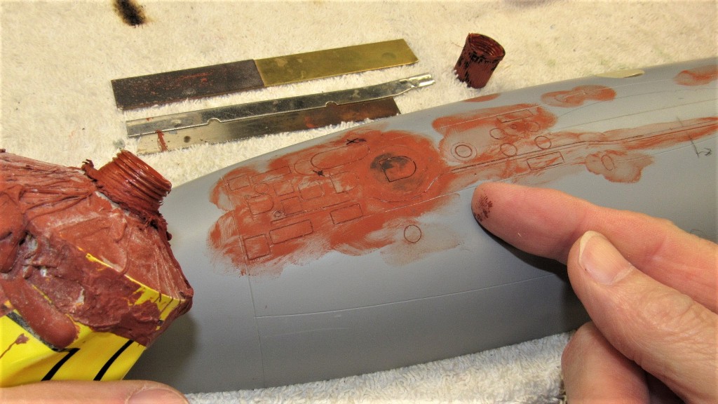
Any way, it was a relatively easy matter to deepen the engraved lines in a GRP substrate than it would have been had the underlying material been wood. I was grateful for that. Inevitably, as I worked the engraving with scratch-awl and razor saw I invariably buggered up some of the work with over-strikes and miss-directed passes. I would work a section then lay down some air-dry putty, chasing out the properly engraved lines before the putty could dry thoroughly. After sanding, what was left were deepened, narrow of width engraved lines.
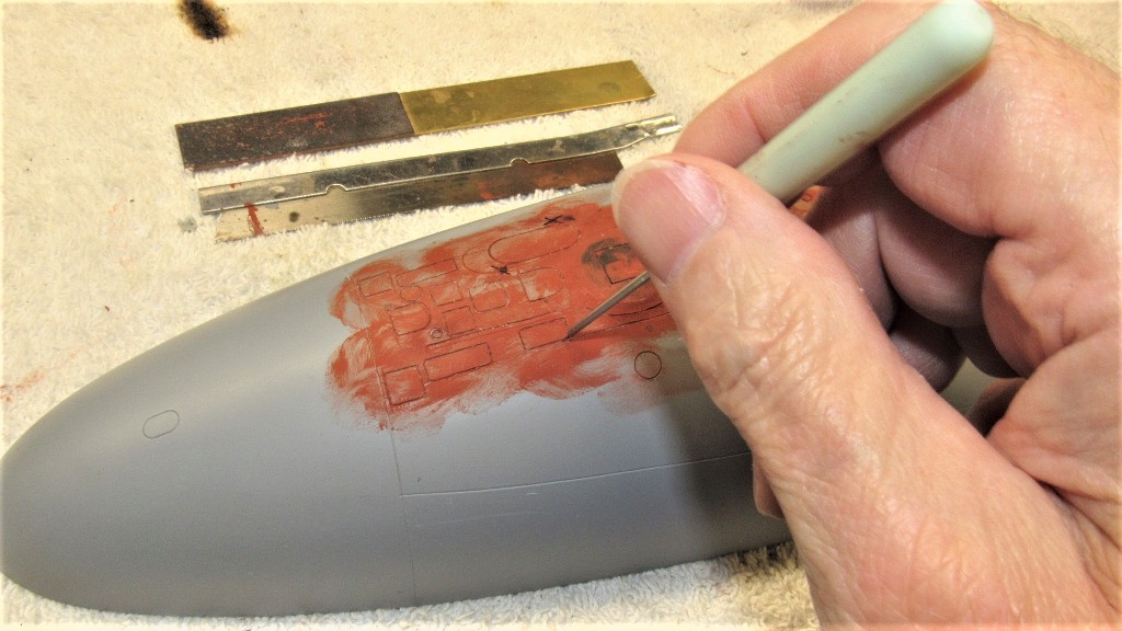
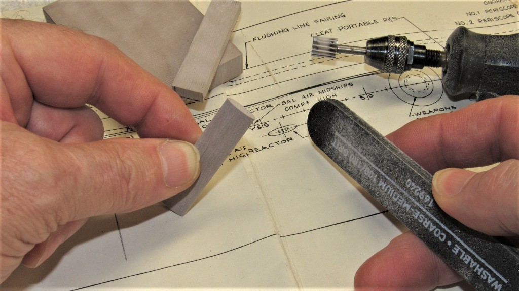
Special sanding tools were employed -- specifically brass strips with #400 glued to one face and #600 to the other – to insure only the puttied areas were knocked down as I wet sanded the dried putty. Particular care was taken on the escape trunk flats and surrounding fairing.
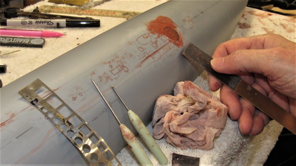
Once happy with a section of the hull, I applied a light coat of gray primer. Repeating the examination-putty-sanding-priming steps as many times as required.
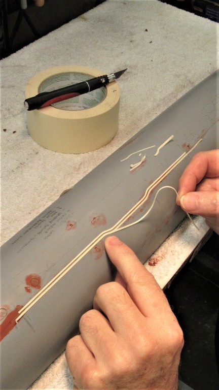
Additional scribing included enhancement of a cheat line for the anti-foul boarder on the deck, as well as the designed waterline had to be completed forward of the sonar dome radial line – that radial line can't be seen in any photos of the real boats, so I softened it with putty.
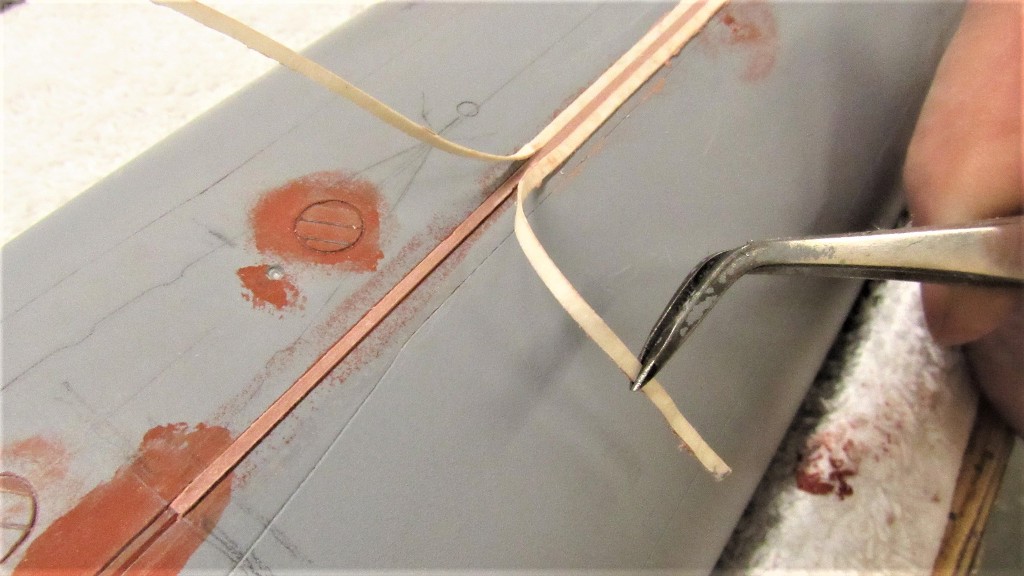
The master did not represent the raised portion of safety-track welded atop the pressure hull portions of the submarine. I built the raised portions of track from Bondo between three plys of masking tape. Making the masking strips narrow gave them the flexibility to negotiate the tight radius jogs you see here:
A small amount of Bondo was catalyzed and screed between the two parallel masks.
Before removing the masking the top of the Bondo safety-track was coated with thin formula CA to strengthen the porous Bondo. The masking was removed and a little work with file and sandpaper, and the safety-track was done.
Three hydrophones are prominently displayed sitting atop the hull on most units of the STURGEON class submarine. These items would be impractical protuberances on a master used to create a hard-shell type tool, but are a welcome enhancement when captured faithfully and without fear of entrapment when giving form to a glove type mold. These items were formed from 40 lbs. RenShape pattern making medium and glued to the deck of the hull master.
Along the deck of a STURGEON class submarine are situated brackets that stand slightly proud of the hull, these foundations accept and make fast to the hull 'portable cleats' used to secure mooring lines between ship and pier – these heavy, hard to hold toe-crushers had to be shipped up and down the escape trunk ladders every maneuvering watch. Total nightmares for the deck gang I heard.
Square indentations in the hull master would impart the same to the eventual model parts. Cast metal brackets would fit those hulls during model assembly.
I first drilled then gouged out rough square holes, then back filled these depressions with Bondo and before that hardened I placed a square tube in the depression to refine its square shape. The form removed once the filler had hardened. Saliva, as it turns out, is a fine part-release!
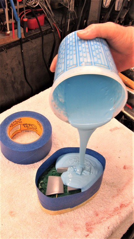
The hull masters are just about done. Now to rub down a few layers of mold-release wax, mount the masters to their respective mold-boards, and to start laying down repeated layers of brushable RTV mold making rubber to form the glove-mold.
Who is John Galt?Comment
-
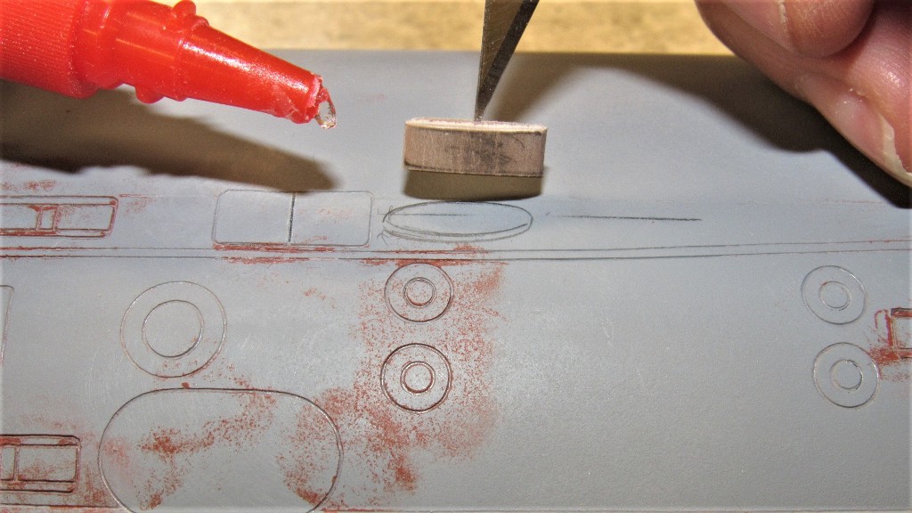
One last detail item I put to the upper hull master was little indentations around the two escape trunk hatches -- these cheat-marks denote were little holes will be drilled into the eventual GRP hull to accept padeyes. These representing hard-points used by the McCain Rescue Bell hold down turnbuckles during a crew rescue operation.
Incidentally, the STURGEON class boats were the last American combatants configured with marker buoys and hold-down padeyes. From LOS ANGELES on all American submarines would rely on the DSRV system to rescue a crew on a stranded boat. Guess, what, sports-fans?... We don't have DSRV's anymore. WTF?!
Before mounting the two hull half masters to their mold-boards I first laid shown a sheet of parchment paper between the base of each master and the face of the mold-board -- this to keep the very sticky glove making rubber from sticking too tightly to the mold board.
I used a pen loaded compass to mark off a stand-off between base of a hull master and where I wanted the eventual build up of RTV glove rubber to stop.
I waxed the masters to insure a clean, easy parting of the eventual RTV glove mold when the time came. I've made gloves without the wax without any stick problems, but I'm getting ever more conservative and careful with old age.
After rubbing the wax into the work I used a sharpened dowel to chase out wax from all the engravings.
And finally starting to lay down the, what will be many, layers of 'brushable' RTV mold making rubber.
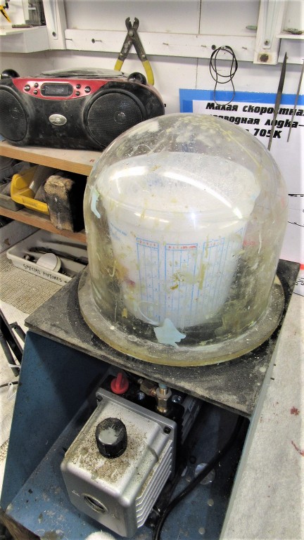
The catalyzed rubber has to be mixed thoroughly, which folds in a lot of big air-bubbles. These have to be eliminated before application by subjecting the mix to a hard vacuum.
Who is John Galt?Comment
-
Something I failed to mention was my use of two heat-lamps to accelerate the cure of the glove-mold rubber. As Winter is on us and the shop is correspondingly cooler I found it necessary to keep heat on the work if I was to get all the work done in a reasonable amount of time.
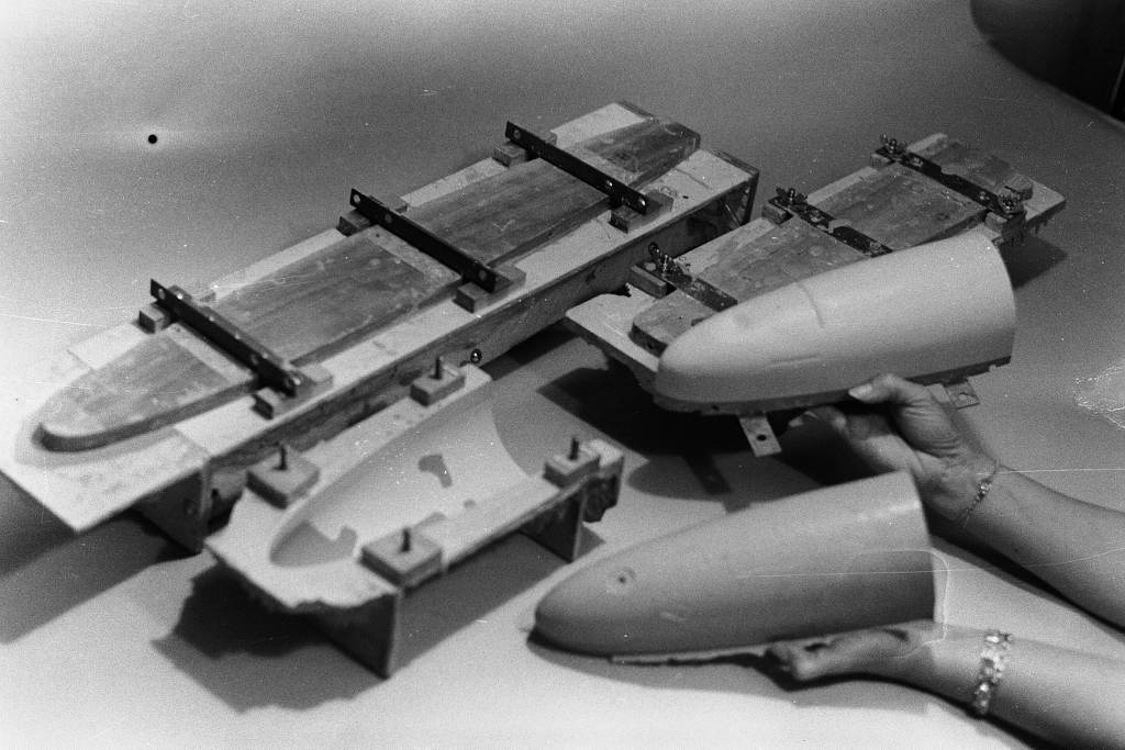
Duplicate items on the submarine -- fairwater planes, stern planes, and horizontal-vertical stabilizers -- were not provided, only one each. No problem as each item is a mirror of its eventual doppelganger. So, I made a rubber tool off the three provided masters and would, later, cast two production masters of each item.
A mold-board for this quick and dirty resin casting tool was cut out from an old strong-back. This would be a platform over which I would lay down a thick mask of oil based clay.
The mask permits only one-half of a master to be covered by the RTV rubber that forms the first half of a two-piece tool.
A masking tape dam was wrapped around the clay and catalyzed RTV rubber poured in to cover the masters. Note that I've indexed the face of the clay -- which forms the interface flange between the two eventual tool halves -- with dimples. These keys would insure correct registration of the two tool halves later.
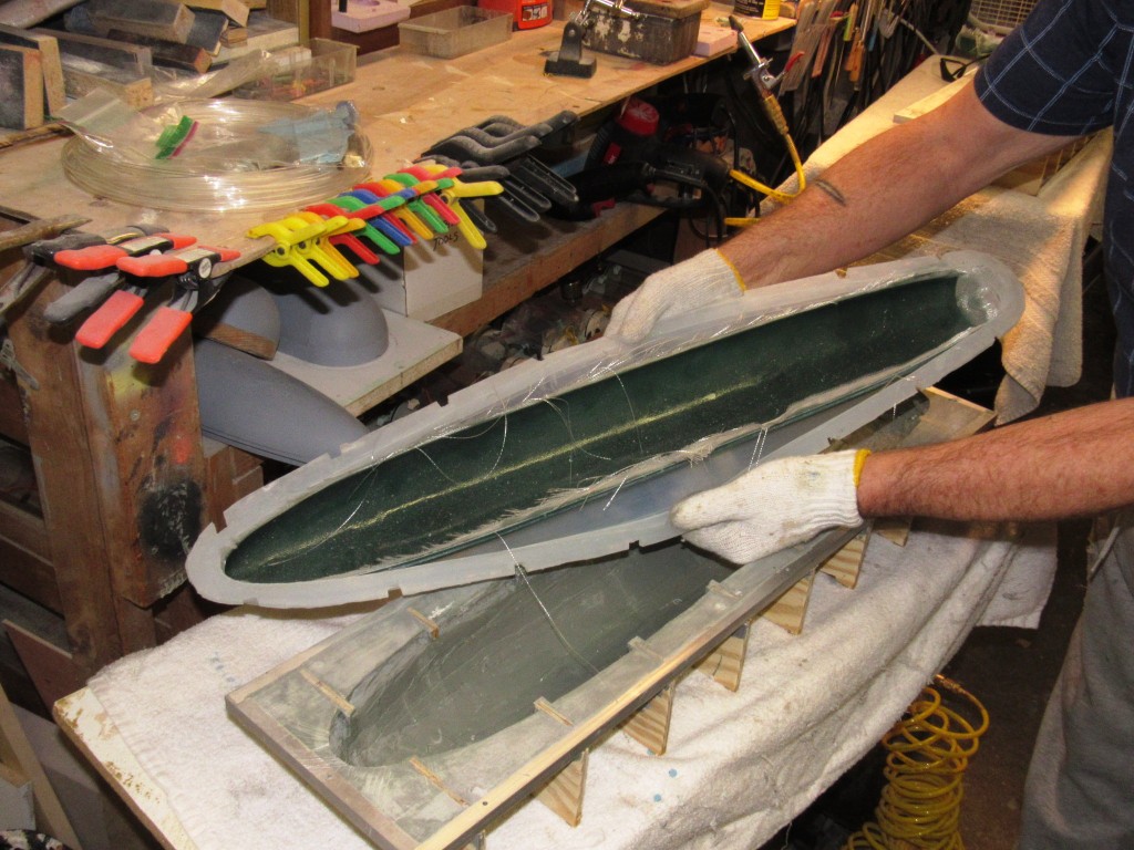
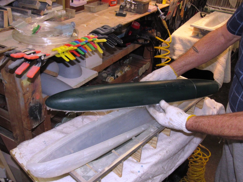
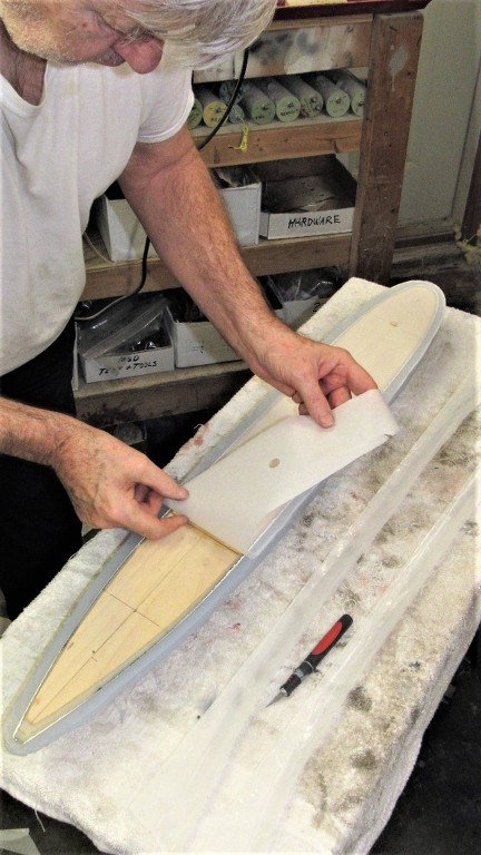
I used an entire one-gallon kit of TC-5040 RTV mold making rubber to form the glove. This resulted in the desired nominal wall thickness of about 1/2". Next move was to pop the two half-hull masters, now coated with thick gloves, off the mold-boards, trim away excess rubber from the flanges, and to prepare things for creation of the hard-shell mother-molds that would interface with the glove and provide the floppy rubber with a firm foundation.
Each hull master was unscrewed from its mold-board and removed. Inverting the masters with the Parchment paper facing me -- which had been previously inked as to the desired thickness of the glove to guide me as I knifed away excessive rubber from the base of the glove. The glove remains attached to the master. The parchment paper was stripped away, and the mold-board readied for re-attachment of the masters with attached gloves.
To assure that the eventual interface between glove and mother was firm I punched out vertical groves to the sides of the glove flange.
I laid down a fresh parchment, secured the masters to the mold-boards, waxed the gloves and parchment paper, made up the egg-crate support structures, and I was ready to mix up and brush on the tool making resin that would give form to the hard-shell mother-mold.
Who is John Galt?Comment
-
This should DEFINITELY BE in the book.Make it simple, make strong, make it work!Comment
-
No 3D Printed boat will ever come close to the type work you do David!
Rob
"Firemen can stand the heat"
"Perfection Is Our Goal. Excellence Will Be Tolerated."Comment
-
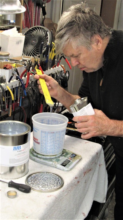
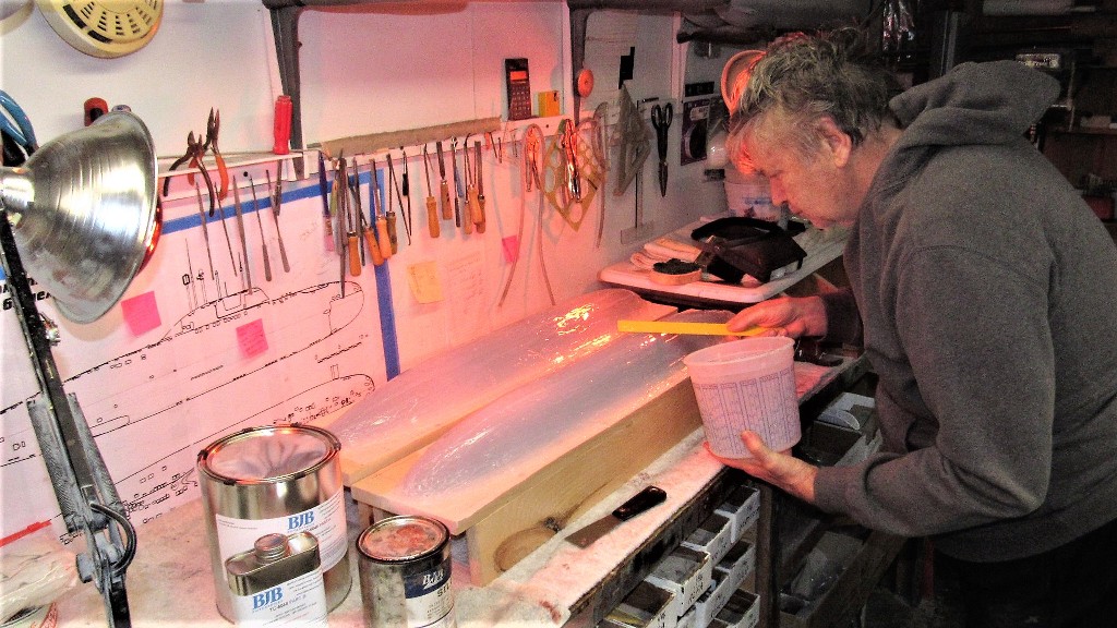
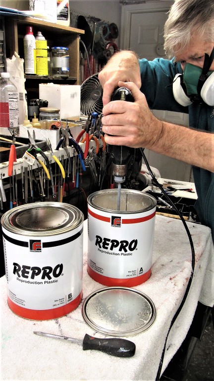
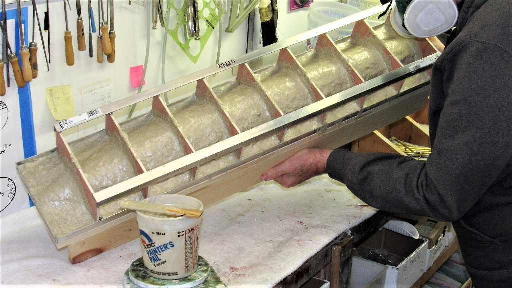
The mother-mold was manufactured by brushing a special polyurethane 'tool making' resin, available from Freeman Pattern Supply Company. I use the Repro brand. This quick-cure, two-part resin is brushed over both the just completed rubber glove-mold and also saturates the bed of the egg-crate support structure as well as all the transverse re-enforcing frames of the structure. The shell formed becomes a rigid, perfect fit to the rubber glove under it.
As it turned out, the most labor intensive part of the mother-mold fabrication was mixing the A and B sides of the goo that would harden into the shell. Thank god for jiffy-mixers and drill motor!
After screwing down the egg-crate down tight onto the mold-board I took the precaution of covering the screw heads with clay. This would later permit me to easily access these screws when it came time to lift the mother mold off the glove-mold. Here I'm brushing on one of the five thick coats of tooling resin
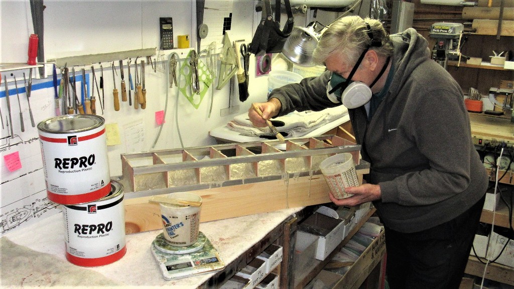
The first coat went on neat. All subsequent coats were mixed with fiberglass shards for strength an to prevent sagging of the still liquid resin. The work went very quickly as the pot life was about ten minutes and the stuff would harden enough to permit another coat in only twenty-minutes. Great stuff, and it eventually cures to rock hard.
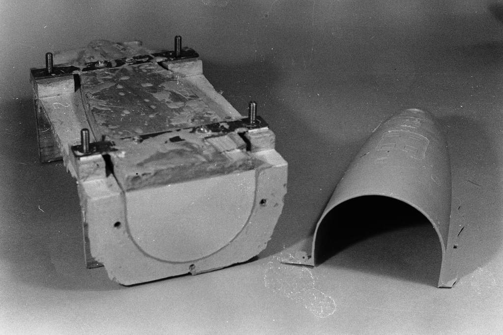
Digging away some of the mother-mold shell to access the six screws that secured the mother-mold assemble to the face of the mold-board.
To pop the completed mother-mold assembly away from the underlying rubber glove I used air pressure. I ground away a hole through the mother-mold, stopping when I hit rubber. A quick blast of air and the mother mold jumped off the rubber glove it had been lightly adhered to.
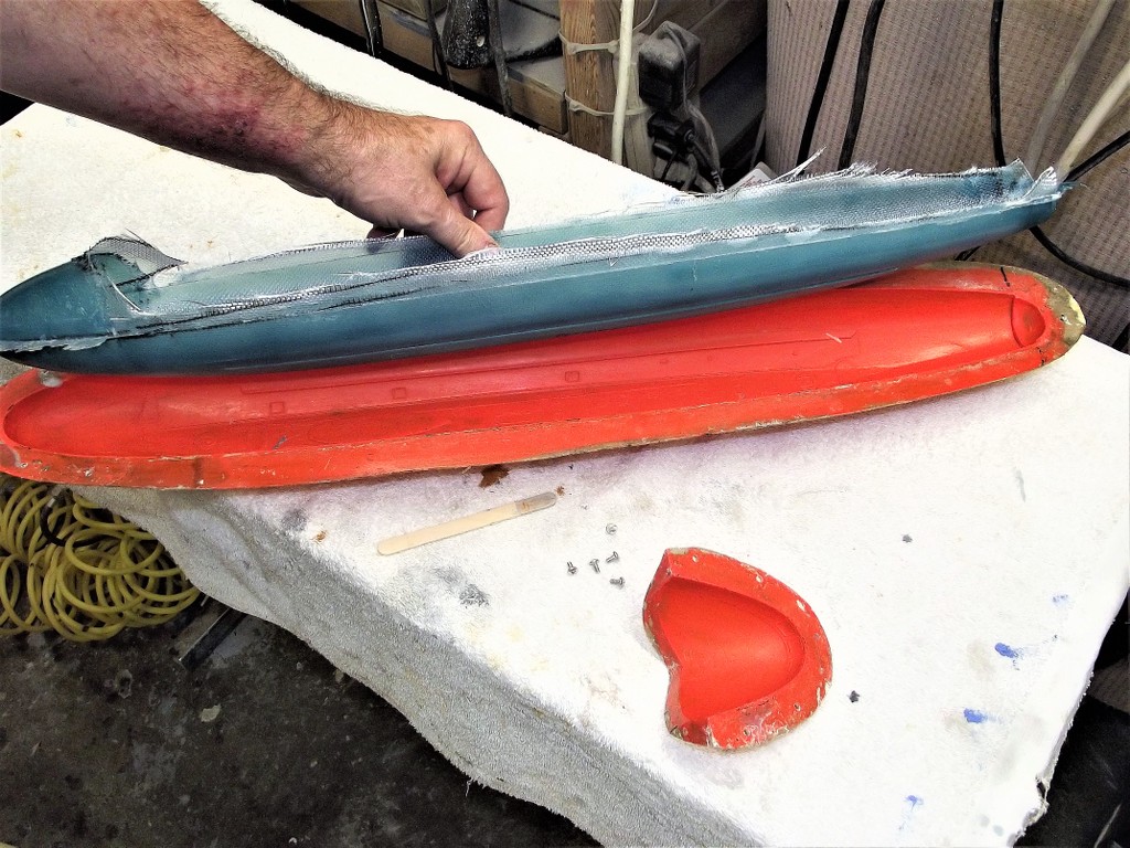
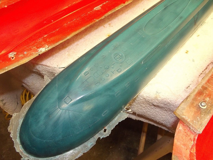
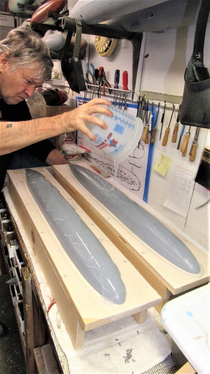
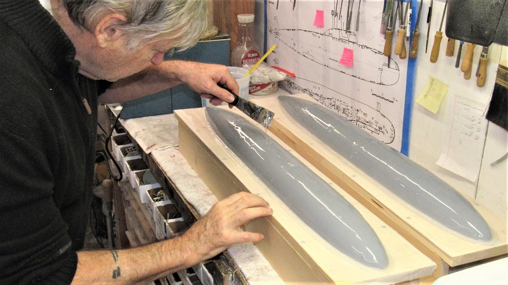
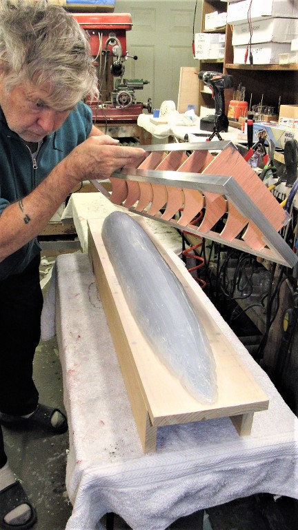
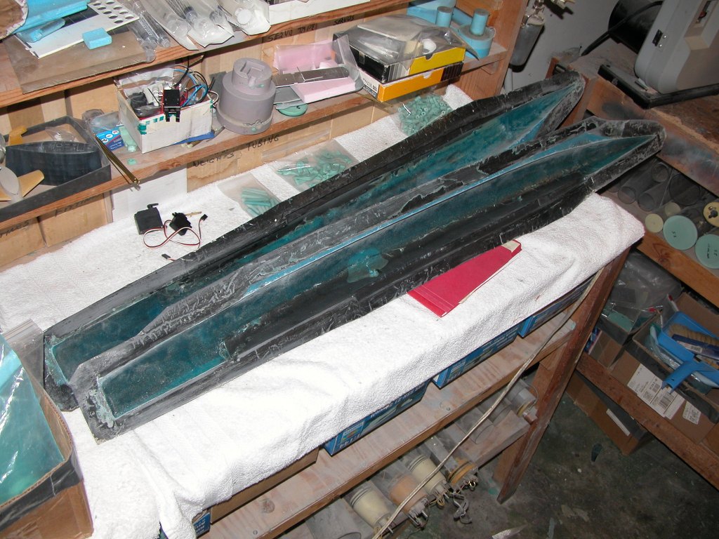
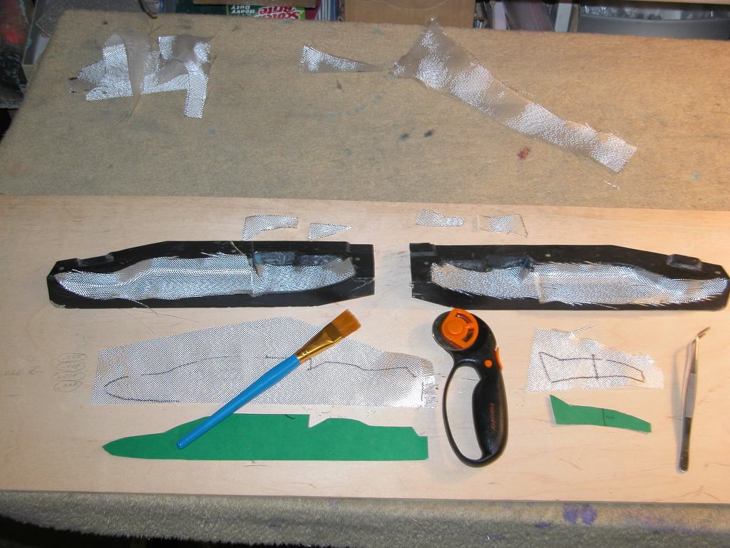
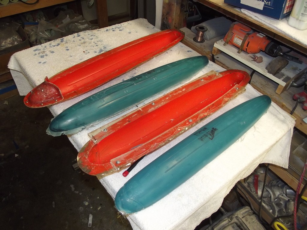
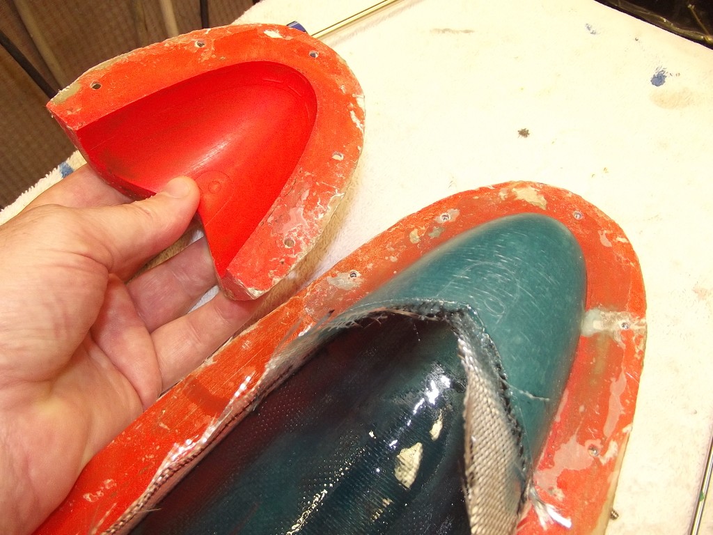
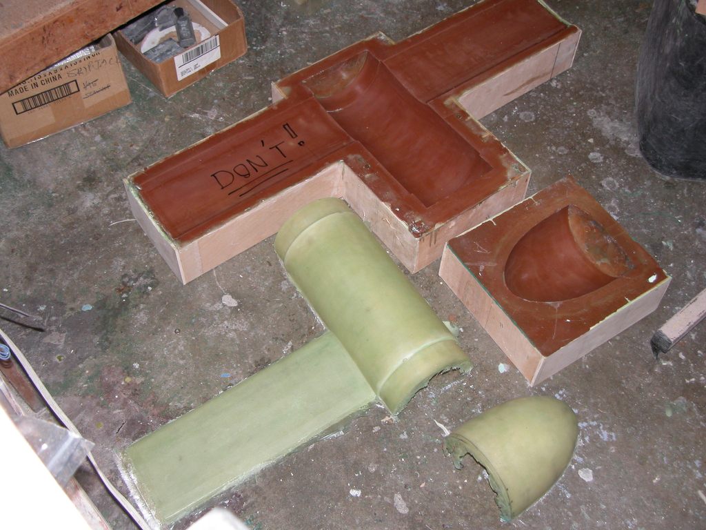
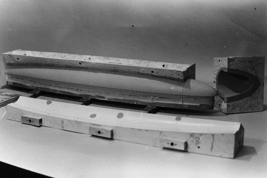
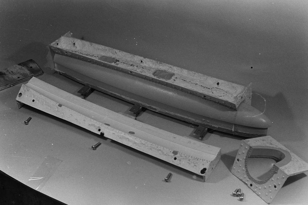
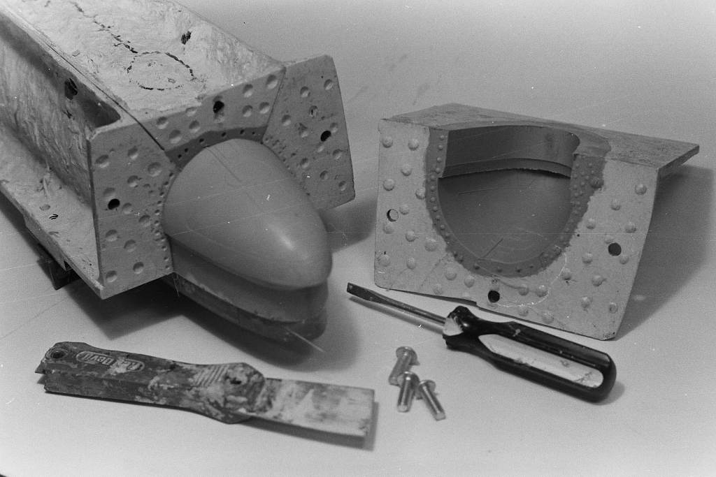
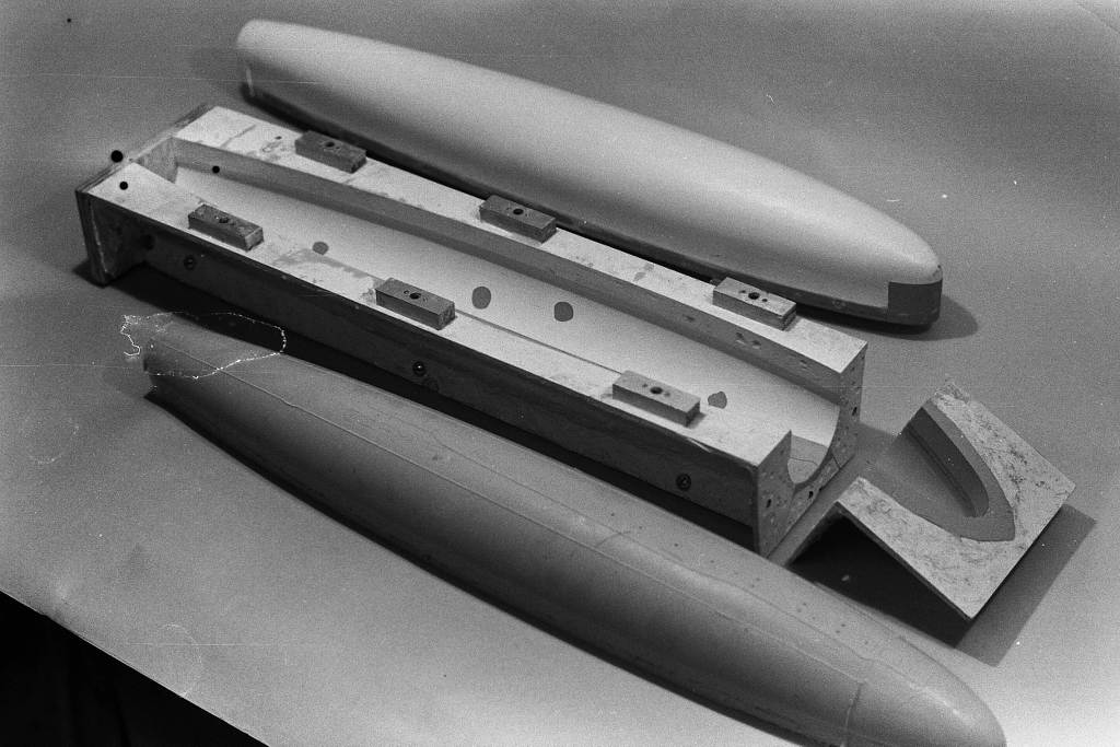
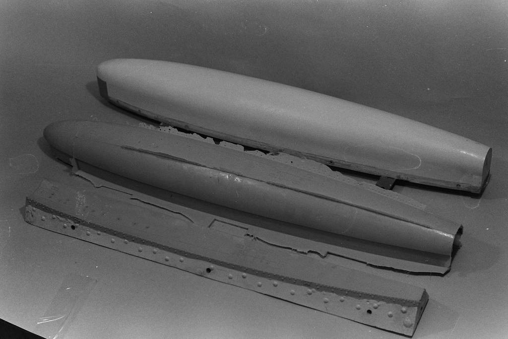
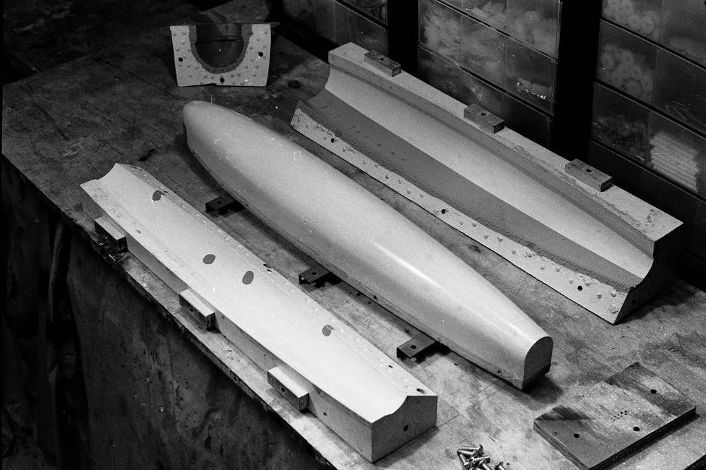
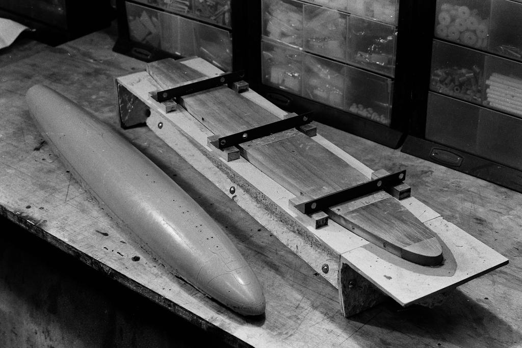
I assembled the tools and set about laying up what would become the master of a complete tail-cone assembly complete with horizontal and vertical stabilizers, stern tube and forward radial flange. That master started life as a fiberglass layup as illustrated here.

Who is John Galt?Comment
-
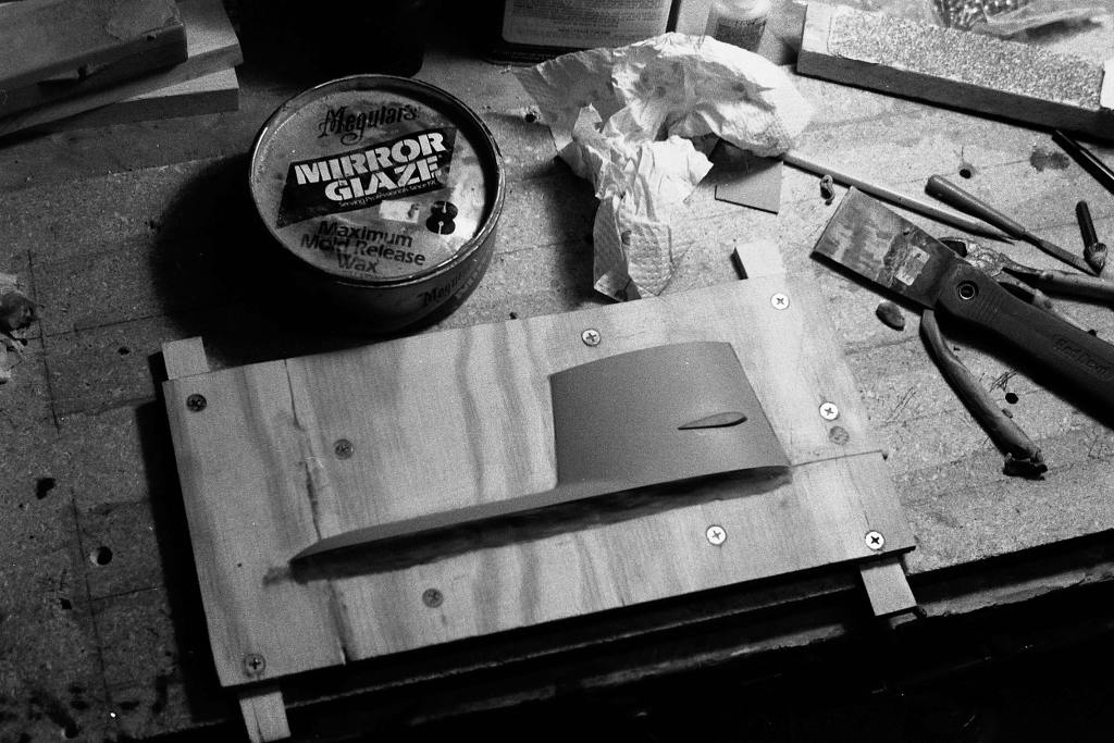
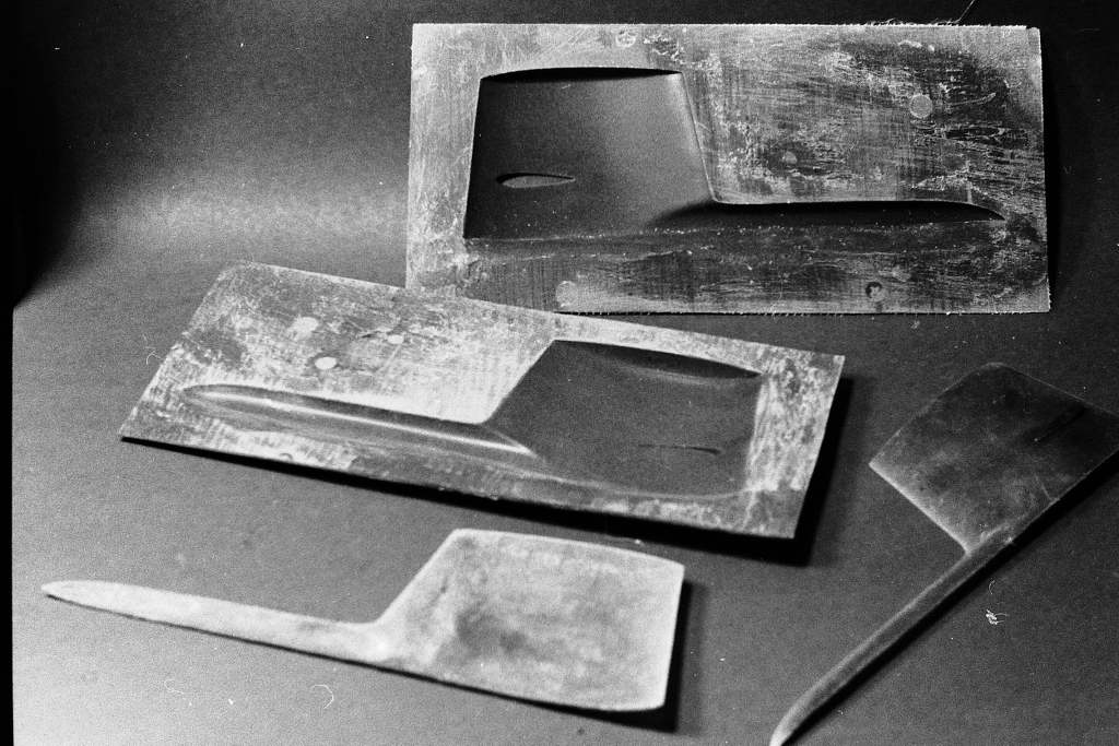
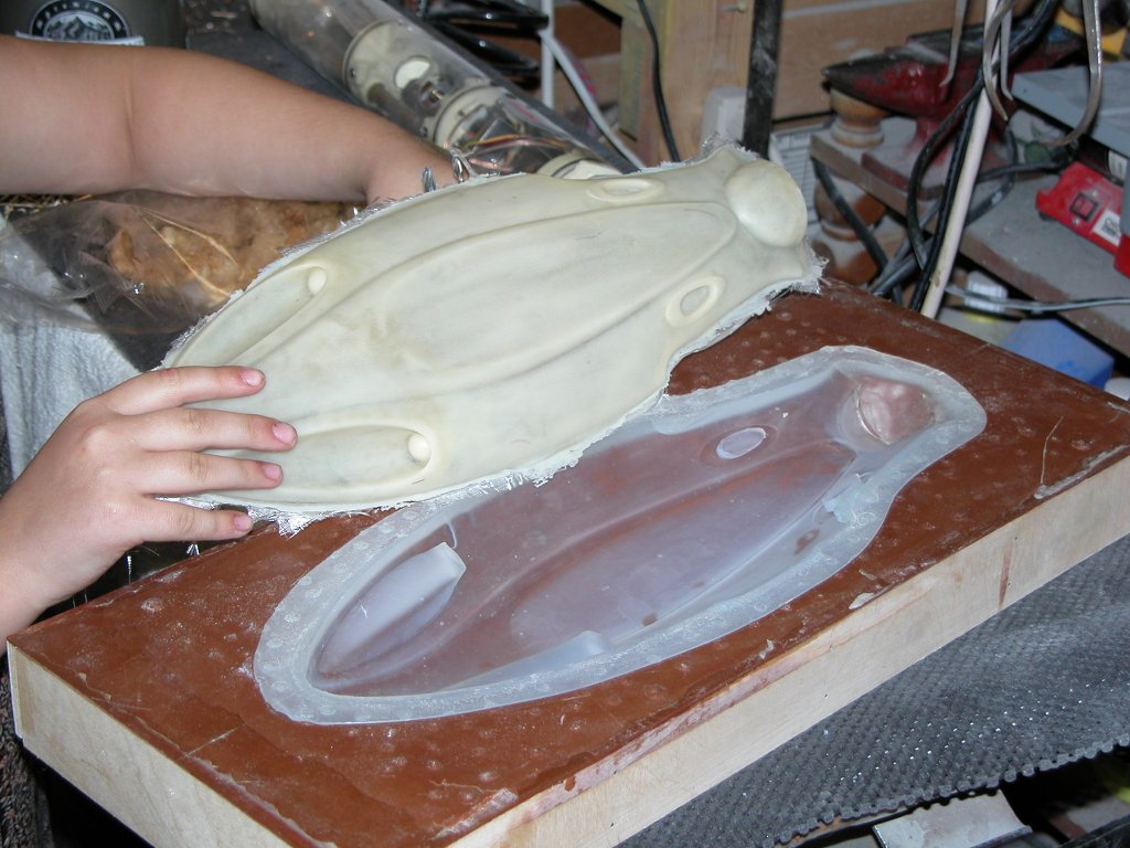
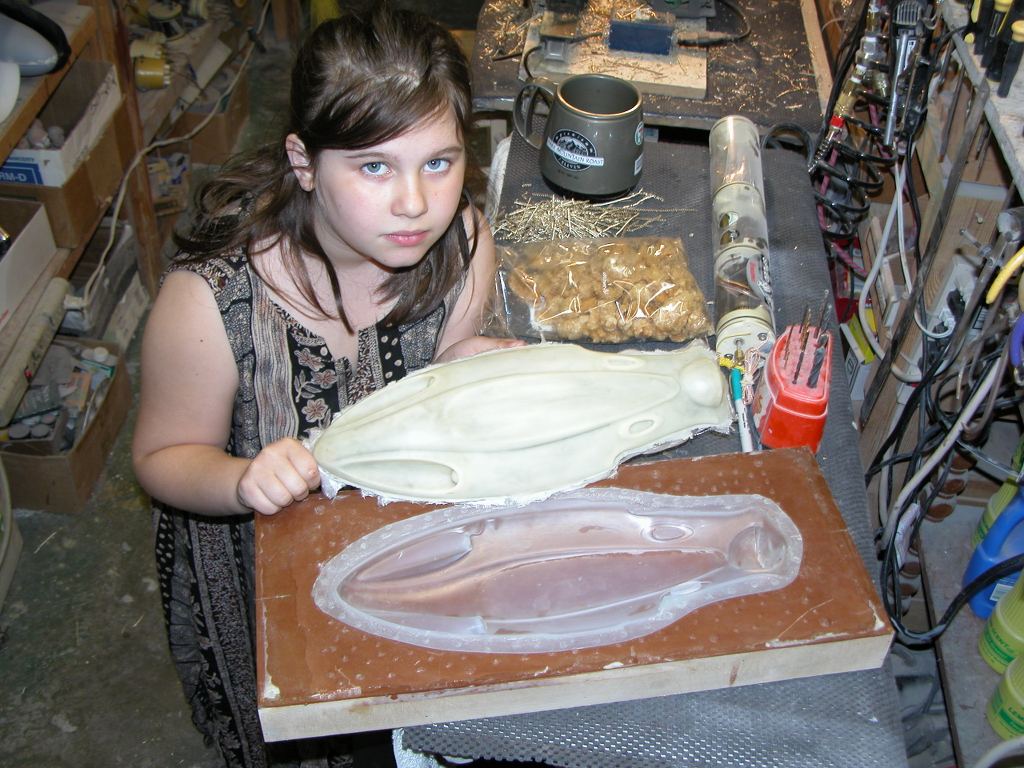
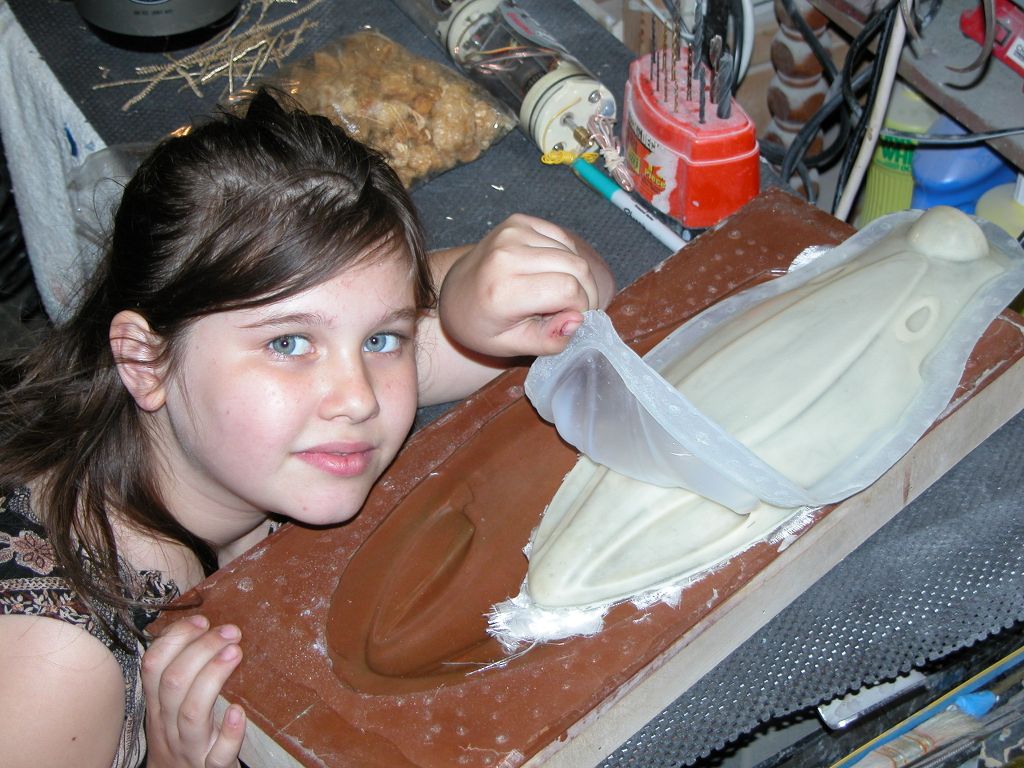
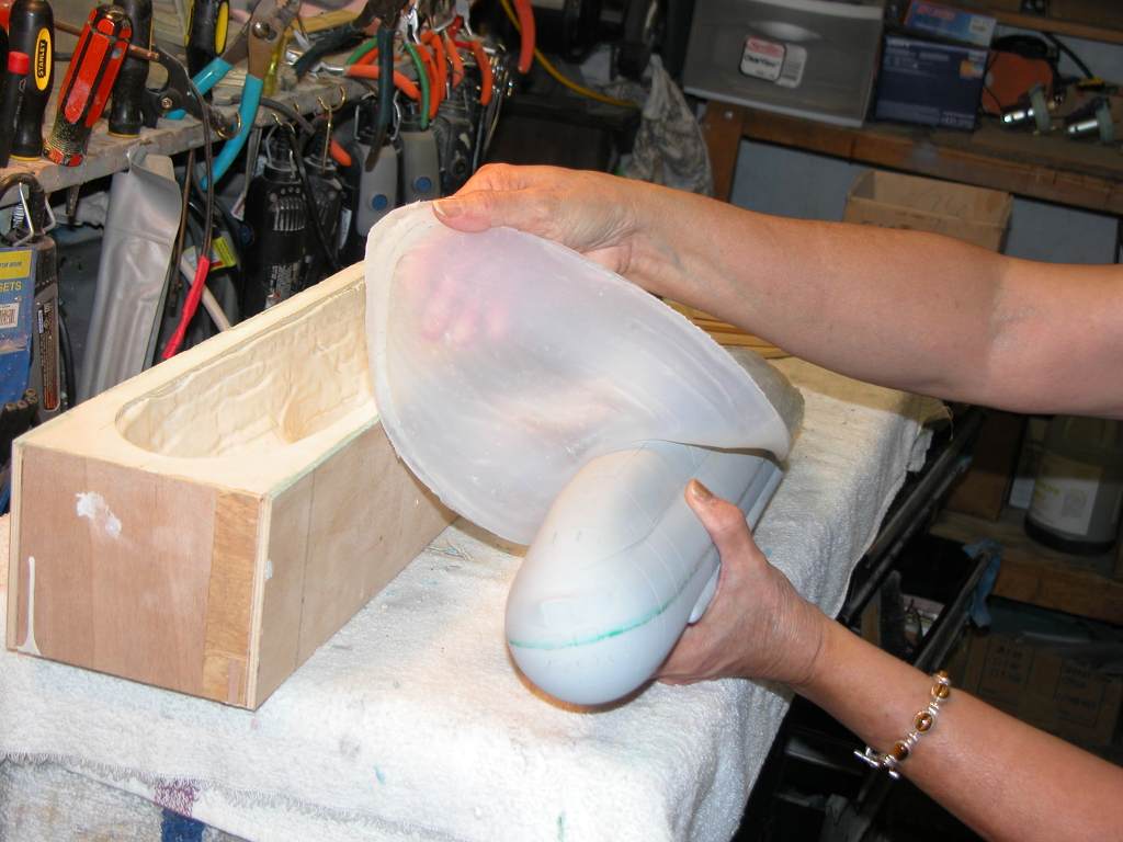
I still make use of other peoples hard-shell tools to produce product.
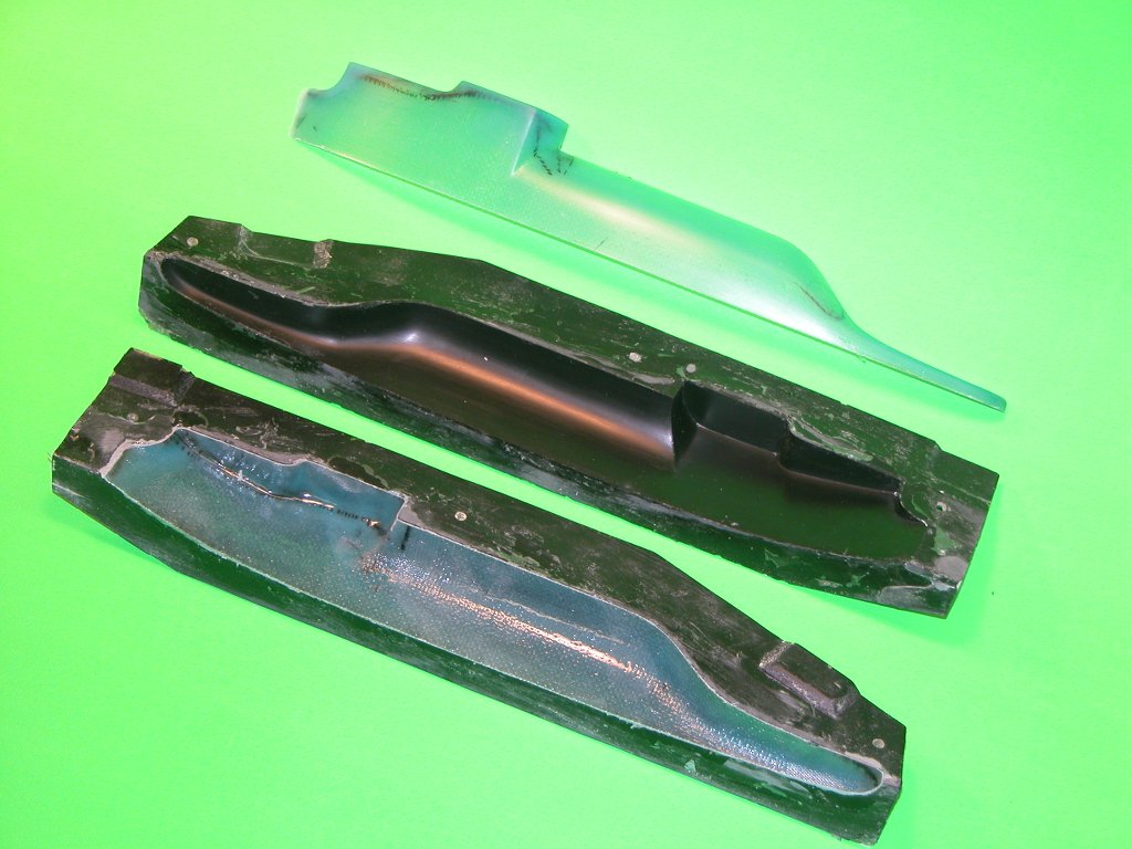
I believe the last hard-shell GRP production tool I produced was back in the mid-90's: an early effort at some production tooling for our SKIPJACK kit, specifically, the sail. Here you see the master on its mold board about to be built up upon by layers of glass cloth and resin to form the hard-shell tool. And the completed tool used to produce production GRP sail parts. I have since converted to a rubber tool from which resin sails are produced.
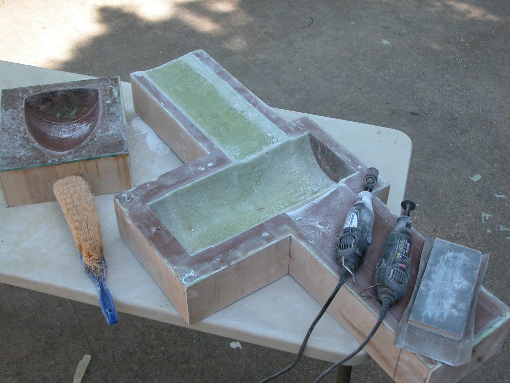
Oh, wait a minute... just found these shots that make me a liar: Ellie and I did a job for MIT in the early 2000's that made use of quick and dirty hard-shell tools:
Ever since then all tools designed for GRP part production have been of the glove-mother mold type, with variations on the theme. My first one was a hybrid that was a traditional hard-shell with rubber inserts that captured all the high draft and engraved details. A tool that embodies the virtues of both hard-shell and rubber contact surfaces.

In addition to the use of rubber elements in the tool to capture detail that a hard-shell element can't, I also developed the 'displacing plug' version. This addition to the tool insured a uniform inside form to the GRP part as well as affording the opportunity to incorporate detail and structures you might want on the model hulls interior.
In my current version (the more traditional form of the tool) the rubber element (the 'glove') is removable from the hard-shell resin (the 'mother'). That is vital as away from the mother-mold, the rubber can be peeled back -- like a glove... duh! -- away from the GRP part which it gave form.

Who is John Galt?Comment


Comment