German Type 212A 3D Print Build

Collapse
X
 
  • Time
  • Show
Clear All
new posts
  • rwtdiver
    Vice Admiral
    • Feb 2019
    • 1796

    #46
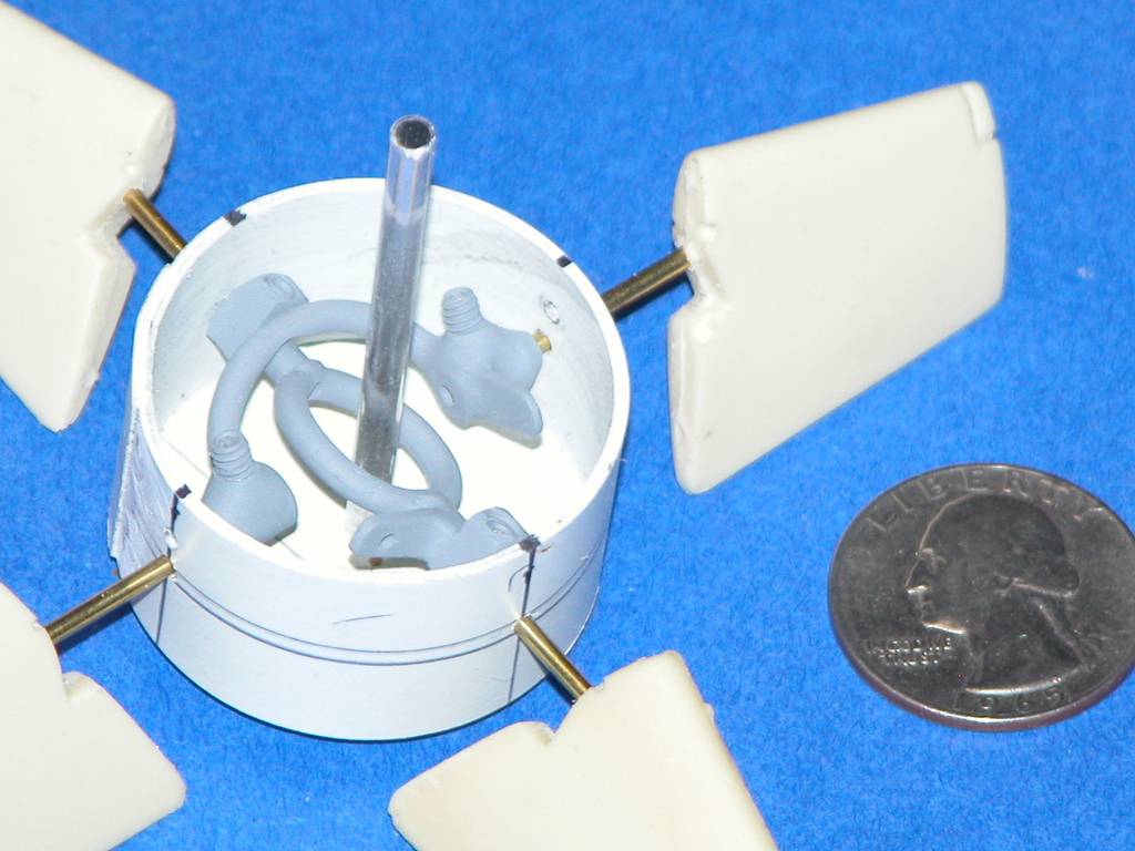
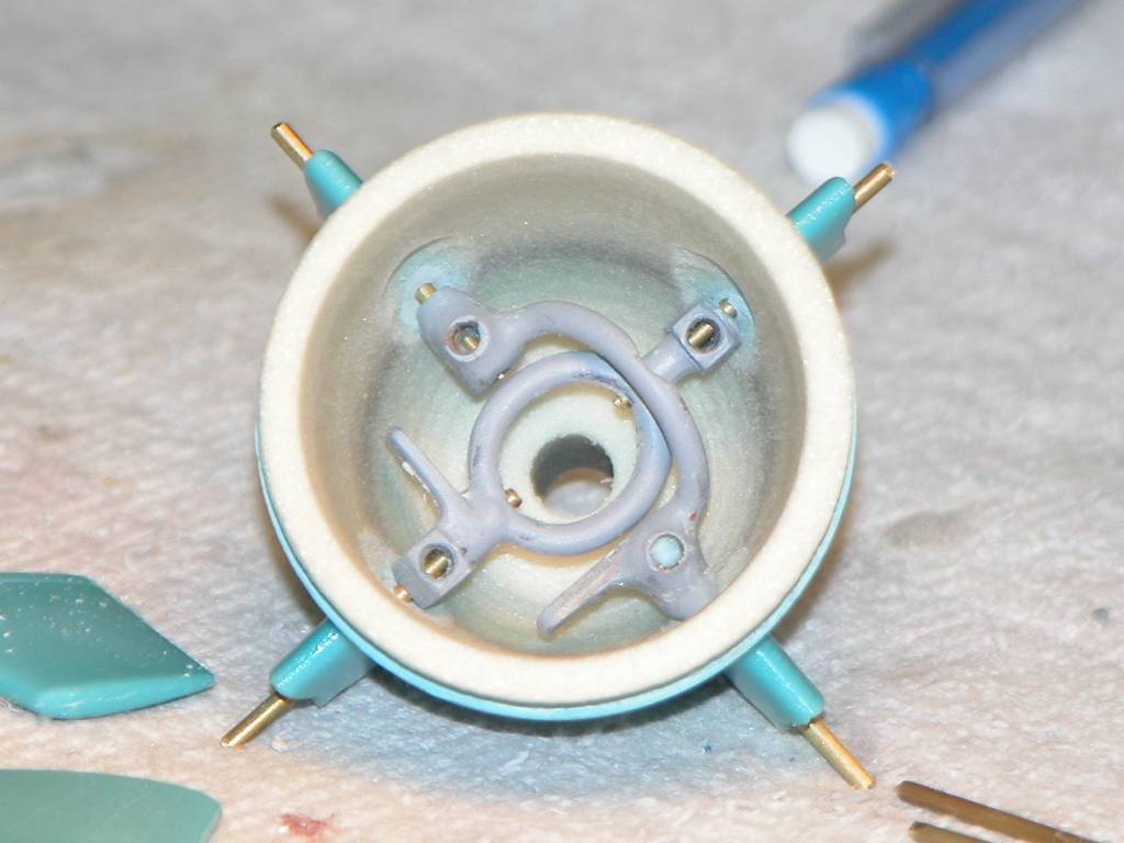
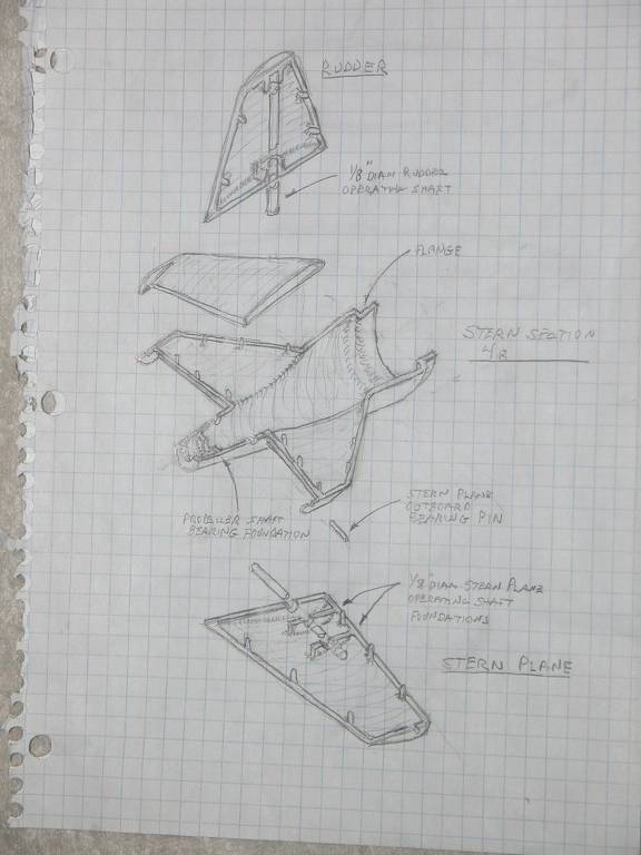
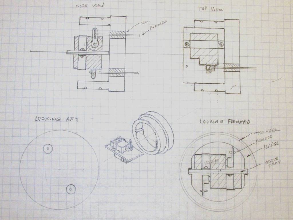
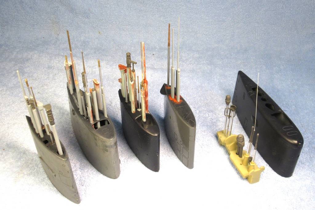
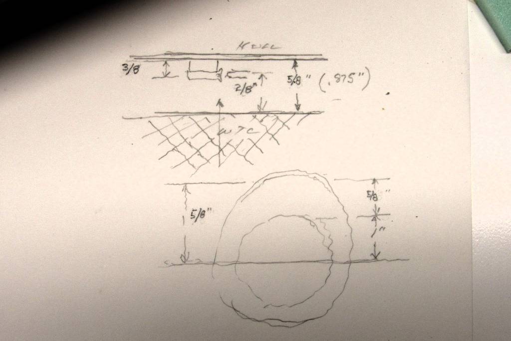
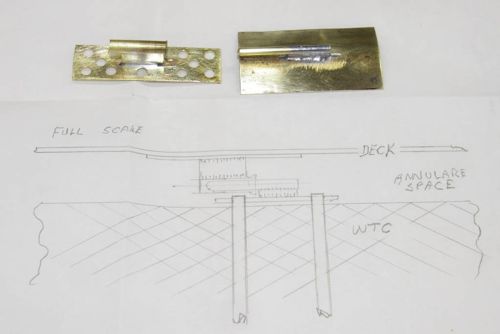
    After looking at the different types of stern linkage systems, I have decided to go with the one that Bob Martin uses on his 212 A Kits.

    Click image for larger version

Name:	GERMAN 212 A 46.jpg
Views:	136
Size:	59.9 KB
ID:	178928

    Click image for larger version

Name:	GERMAN 212 A 47.jpg
Views:	124
Size:	45.4 KB
ID:	178929

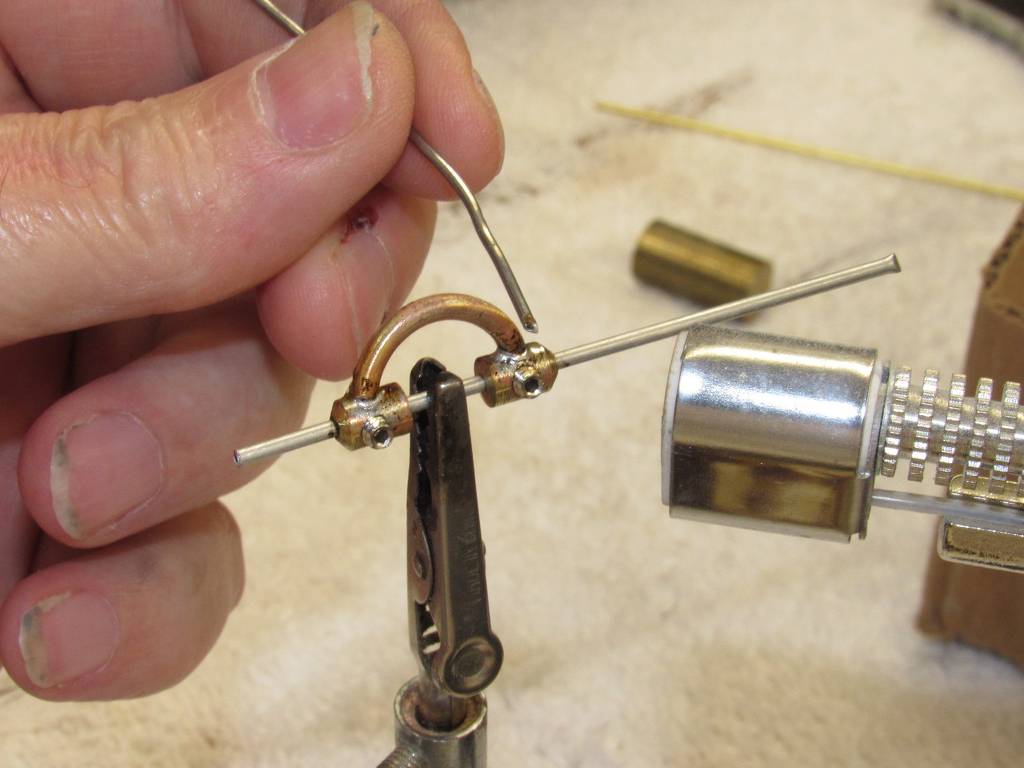
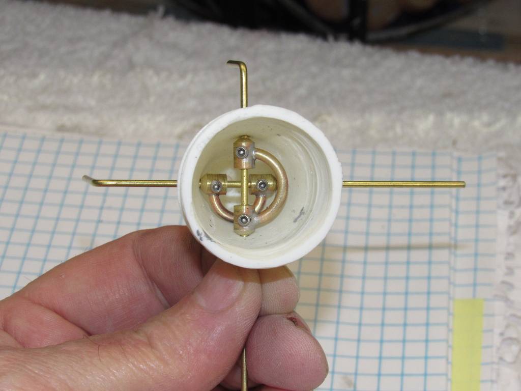
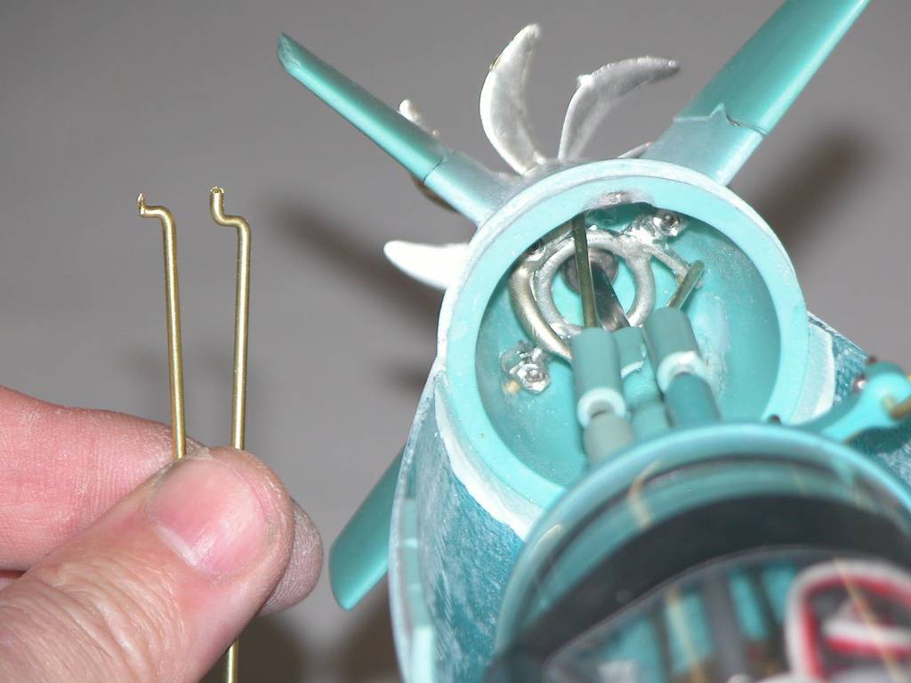
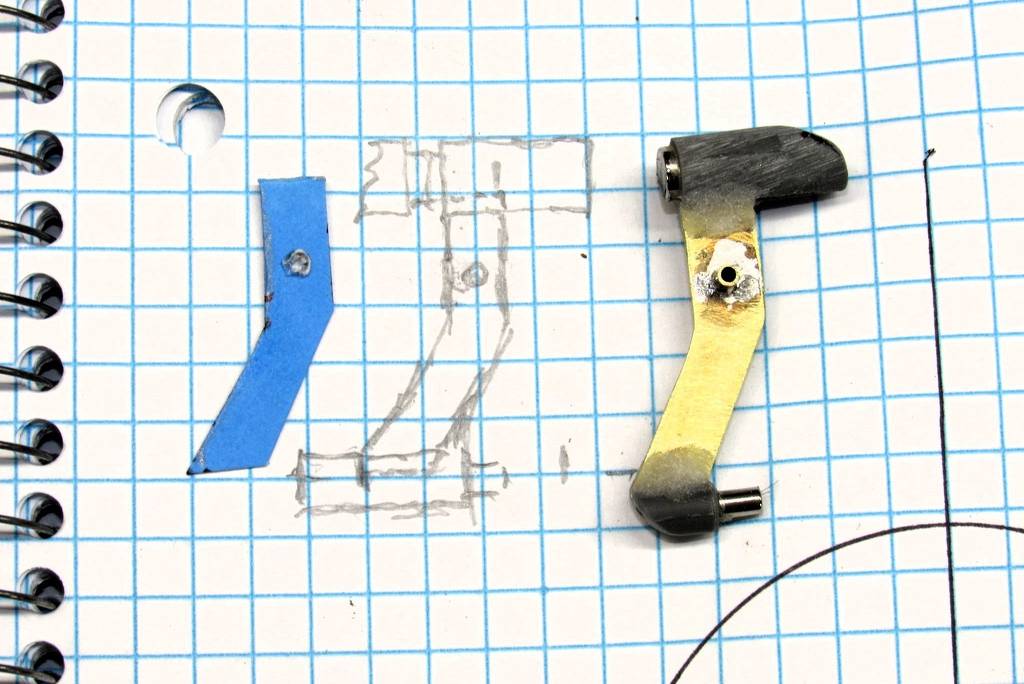
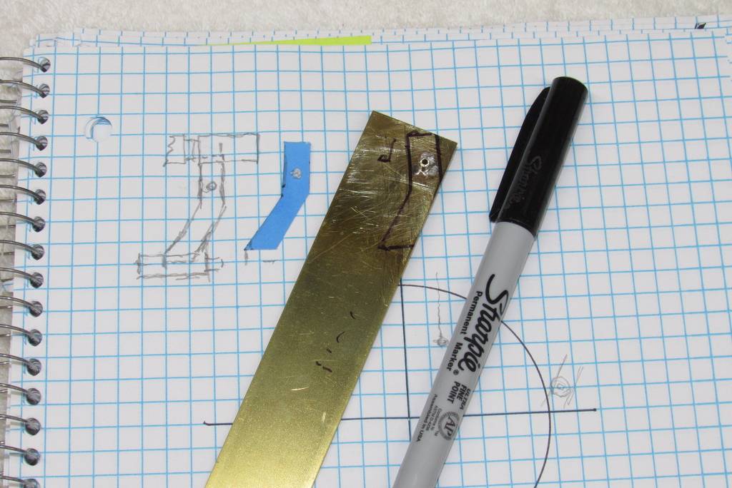
    With the stern section being open as it is it should be relatively simple to put together. I soldered up the brass horns about 3 weeks ago, so I might as well use them.

    Rob
    "Firemen can stand the heat."

    Comment

    • rwtdiver
      Vice Admiral
      • Feb 2019
      • 1796

      #47
      I have the linkages all tied in (I THINK)

      Click image for larger version

Name:	GERMAN 212 A 48.jpg
Views:	133
Size:	50.7 KB
ID:	178931

      Not my most favorite way to link up the stern control surfaces. I may have to go back to the old traditional methods. We will give it a try and see what happens!

      Rob
      "Firemen can stand the heat."

      Comment

      • Albacore 569
        Commander
        • Sep 2020
        • 331

        #48
        Originally posted by rwtdiver

        Steven,

        Our two boats (Dolphin & 212 A) are very similar, especially with the X tail stern.

        Click image for larger version  Name:	DOLPHIN 2 A.jpg Views:	14 Size:	59.0 KB ID:	178921

        I am very impressed with the brass linkage system that you built. Really excellent work Steven! If it is OK with you, I may try and duplicate what you have done here for my 212!? It is a really clean and effective.looking system.

        I can see where your cylinder hold downs would be different because of your PVC hull section.

        Rob
        "Firemen can stand the heat."


        Sure, you can make a duplicate of your own. I am flattered, but I did post here so others could learn from me (or my mistakes...lol) . I am just following others designs too after all. Importantly I would change the overall size and sizes of the same parts to fit into your smaller 212A or there will be clearances issues in a area cramped already.

        The first thing in your model is determine (as what I followed first) what is the largest reasonable diameter solid brass rod for the rudder posts possible that slides into the rudders. Smaller will fit but largest you can use will be the more robust. That will determine the Dubro locking collars sizes (the diameters).

        If you run out of brass solid rod stock, buy more or if have to wait again ordering online delivery, if you have similar sized brass hollow tubing, then slide in concentric tubes inside the larger and solder together. Just as strong, hell same principle worked well for the Supermarine Spitfire's wing spars.

        It took me several tries of making the components to get the soldering down after practice. I used a normal soldering flux, and then silver solder and a small hand torch and a vice, with aluminum tubing acting as fixtures to maintain alignment (critical). I then used rubber wheels in a hand piece to clean up the parts after soldered and smooth out the silver solder. 'Merriman and Martin' have illustrations and you tube videos in various places to help guide you.

        Years ago, a suitable anti flux while soldering (creating a barrier where you don't want the solder to flow) could be used with Pencil lead (graphite). Scribble over the area with a pencil. But I noticed that didn't work this time, so I think the pencils graphite must have changed or I have...lol.

        Du-Bro nickel plated shaft wheel collars sizes. In my Dolphin 2, I used 1/8". That was the maximum diameter possible in my case on the Dolphin 2. For your 212A, you have to step size down, so they fit the appropriate size rudder posts.
        • 1/16" (1.5 mm)
        • 3/23" (2.3 mm)
        • 1/8" (3 mm)
        • 5/32" (4 mm)
        • 3/16" (4.7 mm)
        • 7/32" (5.5 mm)
        • 1/4" (6.3 mm)

        Ideally, since you have a 3 d printer, could you follow the public source design and just design and print your own out of suitable strength material? Doesn't Bob provide a suitable linkage for his 212 kits? I see in his videos Bob seems to crank out plenty of his beautiful 212A's for clients too. Just some thoughts.

        My eyes aren't the best either. I just went to the optometrist and getting new up close and far distance glasses. I've been diabetic type 1 for 50 years as of March 19th, 2024. A personal milestone for me that I made up in my mind t keep me going. My eyes seem to have the effects of diabetes over time, but fortunately seem well enough to not need injections or lasers. I hope I pass the DMV drivers test soon. The new Rx glasses should be a huge assist. I got to be able to drive to the ponds to be with you guys' 'Simmerly afflicted' lol. Not afflicted with diabetes, though I have run into a lot in our local group a number of f diabetics' the same age and time but afflicted with model submarines...lol.
        Last edited by Albacore 569; 03-21-2024, 12:29 PM.

        Comment

        • rwtdiver
          Vice Admiral
          • Feb 2019
          • 1796

          #49
          Hi Steven,

          Thank you very much for taking the time to list out what you have done for your Dolphin stern section. I have fabricated a similar type brass yoke for most of my standard + tail designed boats.

          Your right the inside area to try and work with on my 212 is an issue for me. The system that Bob is using on his 212 A kits is the one I have fabricated, but the 1/16" brass rods have way to much flex and are not working for my 3D printed 212. I took "SUB Eds" advice and ordered up some of the 1/16" S.S. welding rod, and I will give that a try. I am sure it will have less flex and be a more stable system. I also have a couple more ideas to help compensate for the tight quarters.

          Thank you again Steven! Your help and ideas are GREATLY appreciated! :-)) As we do in this hobby! Keep working till we get it!

          Rob
          "Firemen can stand the heat."

          Comment

          • biggsgolf
            Captain
            • Jan 2020
            • 733

            #50
            Rob, are you printing this at 1:72 scale approximately 31"? What is the distance from the forward bulkhead cap to the edge of the nose opening? Hope this makes sense! I may build it with Subdriver that has a ballast tank. Need to determine scale I would need for it to fit.
            Click image for larger version

Name:	Image.jpg
Views:	117
Size:	95.2 KB
ID:	178947

            Comment

            • rwtdiver
              Vice Admiral
              • Feb 2019
              • 1796

              #51
              Bruce,

              Here are the dimensions of my hull, and at this point about where the cylinder will be located as well.

              Click image for larger version

Name:	GERMAN 212 A 52.jpg
Views:	116
Size:	68.9 KB
ID:	178949

              The overall length is 31"
              Measuring from the front of end cap to the bow opening is 6"

              Hope this helps you.

              Rob
              "Firemen can stand the heat."

              Comment

              • rwtdiver
                Vice Admiral
                • Feb 2019
                • 1796

                #52
                This is what I think will be my solution to solve the stern section interior!

                Click image for larger version

Name:	GERMAN 212 A 49.jpg
Views:	118
Size:	65.2 KB
ID:	178951 Click image for larger version

Name:	GERMAN 212 A 50.jpg
Views:	107
Size:	51.4 KB
ID:	178952

                I used Simplify 3D slicer to cut the stern section into two separate pieces. This will give me much better access to the control linkage installation. As stated above, I am going with 1/16" stainless steel rod in place of the brass.

                Click image for larger version

Name:	GERMAN 212 A 51.jpg
Views:	105
Size:	58.7 KB
ID:	178954

                Rob
                "Firemen can stand the heat."
                Attached Files

                Comment

                • biggsgolf
                  Captain
                  • Jan 2020
                  • 733

                  #53
                  Originally posted by rwtdiver
                  Bruce,

                  Here are the dimensions of my hull, and at this point about where the cylinder will be located as well.

                  Click image for larger version

Name:	GERMAN 212 A 52.jpg
Views:	116
Size:	68.9 KB
ID:	178949

                  The overall length is 31"
                  Measuring from the front of end cap to the bow opening is 6"

                  Hope this helps you.

                  Rob
                  "Firemen can stand the heat."
                  Thanks Rob

                  Comment

                  • He Who Shall Not Be Named
                    Moderator
                    • Aug 2008
                    • 12318

                    #54


                    Who is John Galt?

                    Comment

                    • rwtdiver
                      Vice Admiral
                      • Feb 2019
                      • 1796

                      #55
                      David,

                      Thank you very much for the great photos and the illustrations. I will be using your brass yoke designs and especially your layout work before your fabrication. I am really starting to appreciate a scale drawing prior to fabrication.

                      Thank you for your time and expertise ounce again David.

                      Rob
                      "Firemen can stand the heat."

                      Comment

                      • He Who Shall Not Be Named
                        Moderator
                        • Aug 2008
                        • 12318

                        #56
                        Originally posted by rwtdiver
                        David,

                        Thank you very much for the great photos and the illustrations. I will be using your brass yoke designs and especially your layout work before your fabrication. I am really starting to appreciate a scale drawing prior to fabrication.

                        Thank you for your time and expertise ounce again David.

                        Rob
                        "Firemen can stand the heat."
                        My pleasure, Rob. The layout process, so unappreciated by so many. Hard to pick the correct road without a road-map.


                        David
                        Last edited by He Who Shall Not Be Named; 03-21-2024, 06:51 PM.
                        Who is John Galt?

                        Comment

                        • Ken_NJ
                          Captain
                          • Sep 2014
                          • 774

                          #57
                          Some of your artwork David looks good enough to frame and hang on the model submarine builder nerd's office or shop! Love the artwork!

                          Here's one I have in my office that a friend did.

                          Click image for larger version

Name:	IMG_3646.jpg
Views:	77
Size:	44.7 KB
ID:	178970

                          Comment

                          • He Who Shall Not Be Named
                            Moderator
                            • Aug 2008
                            • 12318

                            #58
                            Originally posted by Ken_NJ
                            Some of your artwork David looks good enough to frame and hang on the model submarine builder nerd's office or shop! Love the artwork!

                            Here's one I have in my office that a friend did.

                            Click image for larger version  Name:	IMG_3646.jpg Views:	0 Size:	44.7 KB ID:	178970
                            That illustrator provides so much direct and indirect information; all done in two projections of the same item: the plan orthographic permits direct measurements to be lofted to the work (pure layout gold). The bottom perspective projection conveys rough dimensions not suitable for lofting but highlights the three-axis relationship between all items presented. Add a profile orthographic projection to this work and you have everything needed to array the devices presented. Yeah -- I would frame and hang that illustration as well, Ken. Excellent work.

                            Some of my refined illustrative work has appeared in books, one book jacket, instruction pamphlets, industrial house organs, catalogs, box-art, and numerous magazine articles.

                            One book, without permission, mistakenly published one of my three-views as source material -- when in fact it was nothing more authoritative than 'fan art'.

                            David
                            Last edited by He Who Shall Not Be Named; 03-22-2024, 11:10 AM.
                            Who is John Galt?

                            Comment

                            • trout
                              Admiral
                              • Jul 2011
                              • 3547

                              #59
                              I was just amazed at the information dump in your post. David you hit everything from search for lost sub to electronic schematics. Amazing work. I will be downloading these images.
                              If you can cut, drill, saw, hit things and swear a lot, you're well on the way to building a working model sub.

                              Comment

                              • He Who Shall Not Be Named
                                Moderator
                                • Aug 2008
                                • 12318

                                #60
                                Originally posted by trout
                                I was just amazed at the information dump in your post. David you hit everything from search for lost sub to electronic schematics. Amazing work. I will be downloading these images.
                                Crazy idea while sleeping or on the ****ter; discussion with peers; paper-napkin doodles; cardboard study model; detailed shop drawing(s); prototype construction and evaluation; Identify ****-ups; repeat.
                                Who is John Galt?

                                Comment

                                Working...