
I just keep learning and learning. It never ends. Keeps it all alive and fasinating.
-
-
Darrin is on here lurking and learning too. Hope to be posting a build soon. Old gang back together.
DHComment
-
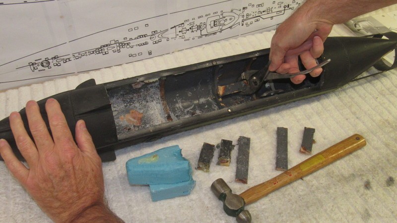
I took a brief break from working out the rudder mechanism linkage... it was making me crazy... and engaged in some emergency aggression therapy. How? By going Mid-Evil with pliers, torch, and a crazed look on my face. That's how!
Some internal hull structures needed removal to make room for the eventual 2.5” diameter water tight cylinder that would contain the propulsion, control, and ballast sub-systems.
The epoxied-in-place wooden foundations were easily pulled out with pliers, as were the two brass pieces of fixed ballast. But the two massive bow plane bushings refused to budge!
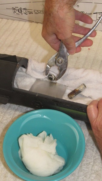
At room-temperature those bushings resisted my twisting and pulling with pliers; they just refused to budge.
(Sorry, Zed, time for a little torch action. Pucker up, pal!).
But, heated...
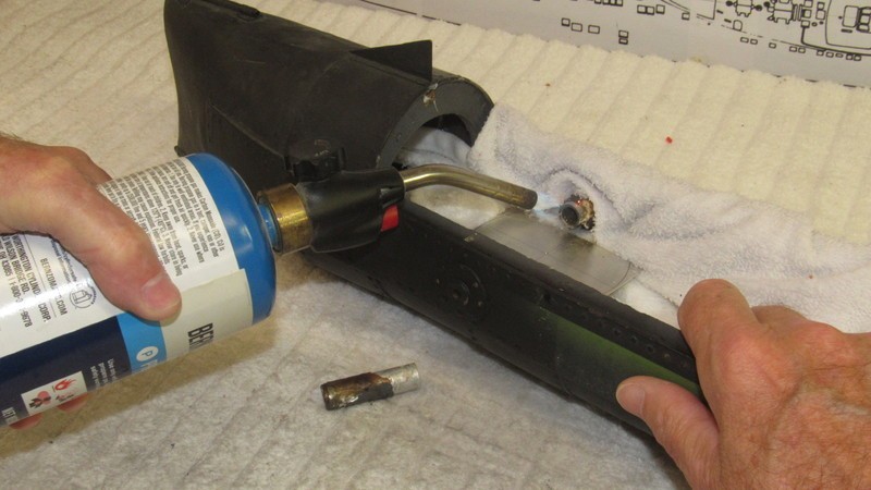
… out they came!
The heat weakened the glue. But before all that I had to protect the surrounding structures from the heat by placing water soaked wash-cloths around the base of a bushing as I applied the heat. In no time at all the glue failed and it was an easy matter to yank the bushings from from the hull. Finally, I had all the room I needed for the 2.5” WTC.
With obstructions removed from the hull I returned to the rudder mechanism.
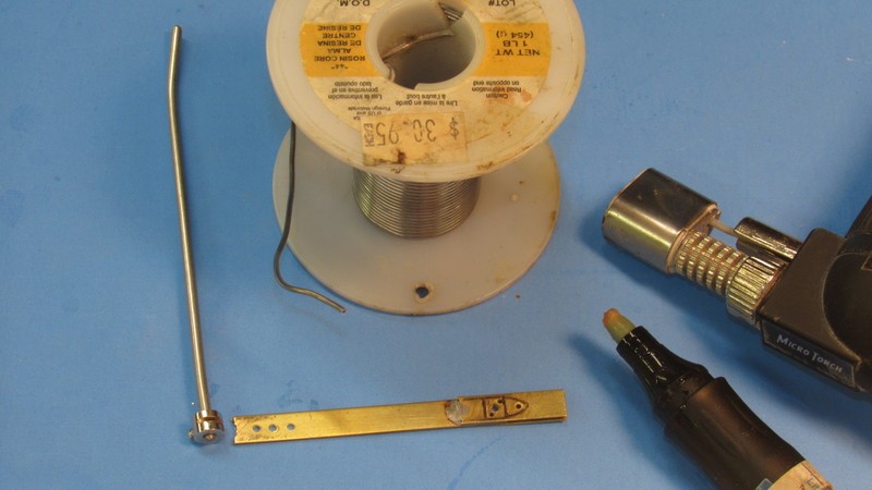
Needed to interface between the WTC's rudder servo and torque rod was a bell-crank. Here you see the completed bell-crank test-fitted to the forward end of the rudder torque rod. It was constructed from an .092” bored Du-Bro wheel-collar and a scrap length of .25” X . 030” brass strip. The two soldered together.
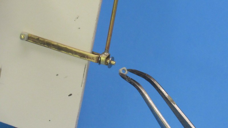
Here's an over-view of all the pieces that make up the HUNLEY's rudder mechanism. The three square 'nuts' started life as a length of plastic model kit sprue. I simply shaved the round sprue into a square section, drilled a 1/16” hole through the end, then razor sawed the required number of nuts. These friction fit retainers were use at the sliding-bail transverse pin, and at the end of the sliding-bail swing-arm engagement pin.
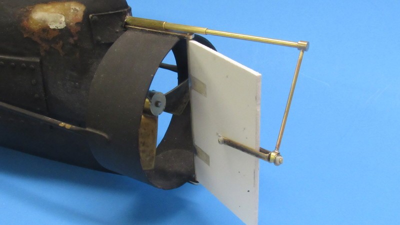
And here's how the gizmo works, sports-fans:
Who is John Galt?Comment
-
Can't wait to see how you make the to and fro output of the control shaft from the subdriver to a rotary motion.Make it simple, make strong, make it work!Comment
-
-
Oh guys, this is really cool. I also collect such a constructor, but only military equipment of the 2nd World War.Last edited by TrevorJackson; 10-04-2021, 03:44 PM.Comment
-
Using a gimbaled propeller to effect pitch control of the model submarine is not a new solution for me. I had to do the same thing on two Disney NAUTILUS models I assembled in the past – a submarine that did not employ proper stern planes (those strake embedded horizontal control surfaces are useless in the real world). Not only did those Disney NAUTILUS models pitch the propeller up-and-down, I made it so the propeller could also translate left-and-right for yaw control. The propeller pitching mechanism for the HUNLEY is substantially easier than what I manufactured for the Disney NAUTILUS models.
I turned an impractical fantasy submarine into a well running r/c model submarine without resorting to the ugly compromise of adding un-scale horizontal control surfaces. Look over this video to see the means and the results:
https://youtu.be/kOO_sz6Sh7U https://youtu.be/cwS6o4jsxoU
So, I'll be doing pretty much the same thing for the HUNLEY which also had no viable means of controlling the submarines pitch-angle once submerged.

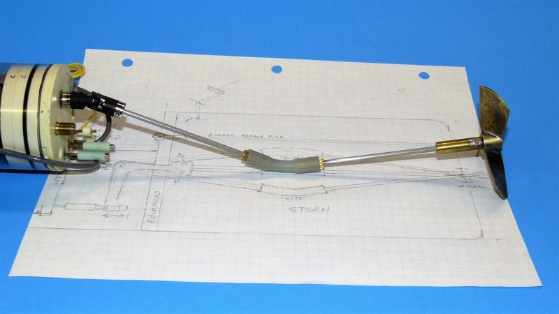
Getting back to the current project for a moment, here is how I will pitch the HUNLEY's propeller for submerged depth-control: Divide the propeller shaft into two halves; place a universal joint between the WTC's motor shaft and the forward end of the forward half of the propeller shaft; connect the two propeller shafts with a simple flexible-hose universal; place a single-axis gimbal at the propeller end; and come up with a means of pushing either end of the propeller shaft up-and-down to direct the propellers thrust line above-or-below the vehicles center of mass. Easy peazy.
With the NAUTILUS jobs I came up with this means of pushing the propeller shaft up-and-down. Keep in mind that this is a complicated affair. Made so, in that example, by the need to produce both pitch and yaw deflections of the propellers thrust line. The mechanism I make for the HUNLEY will do only pitch deflections – it will be a much simpler affair.
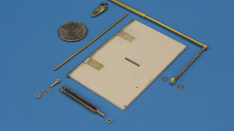
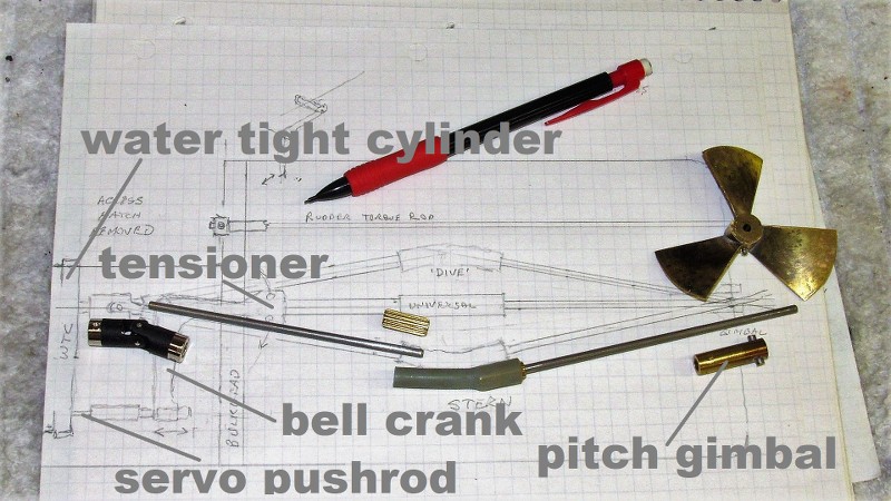
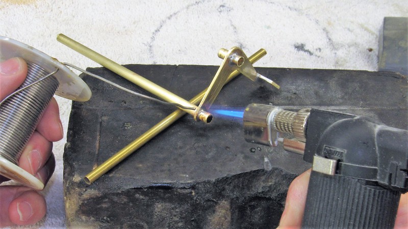
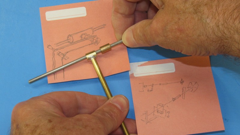
The pitching propeller mechanism started life as a full-scale profile shop-sketch of the models stern. This paper-study helping me noodle things out as I mocked up the components of the system. Here I've already cut the 1/8” diameter stainless steel propeller shaft into two pieces; pressed lengths of brass pinion gear wire into each shaft to serve as splined flexible hose retainers (one already press fit into the after length of propeller shaft); identified and bored out a commercially available universal joint to interface between WTC motor output shaft and forward length of propeller shaft; and, at the extreme right over the drawing, the after length of propeller shaft, propeller and single axis gimbal.
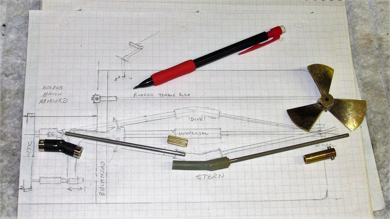
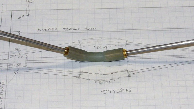
I could have gone with a proper universal joint, like the one hanging off the ass-end of the WTC, but I like simple. The only trick to using flexible hose (silicon being my material of choice) is to employ a hose of substantial diameter and wall thickness to resist twisting as torque increases between motor and propeller. The splined shaft ends insures a non-slip attachment between hose and shaft halves.
The shop-sketch indicates a ten-degree deflection – which this mechanism can achieve with minimal loss to friction – but experience shows that submarine pitch angle maintenance and change can be effected with as little as a three-degree deflection about the pitch axis.
Within the after propeller shaft gimbal is a set of Oilite bearings that insure a well lubricated and low friction fit between gimbal and running gear. The pivot point of the gimbal is about those two pins projecting from the after end of the gimbal. Those pins fit slits of the gimbal foundation glued into the after end of the running gear stern-tube. Several stainless steel washers between the forward face of the propeller hub and after face of the gimbal will serve as ahead thrust bearings.
A similar arrangement within the WTC motor-bulkhead will handle the astern loads.
To drop the WTC low enough onto the wooden frames within the lower hull – placing its motor shaft in alignment with the boats longitudinal axis (shared by the propeller shaft) – required grinding away a significant portion of the frames upon which the WTC would eventually sit. I could just barely get a moto-tool in there to accomplish the rough shaping.
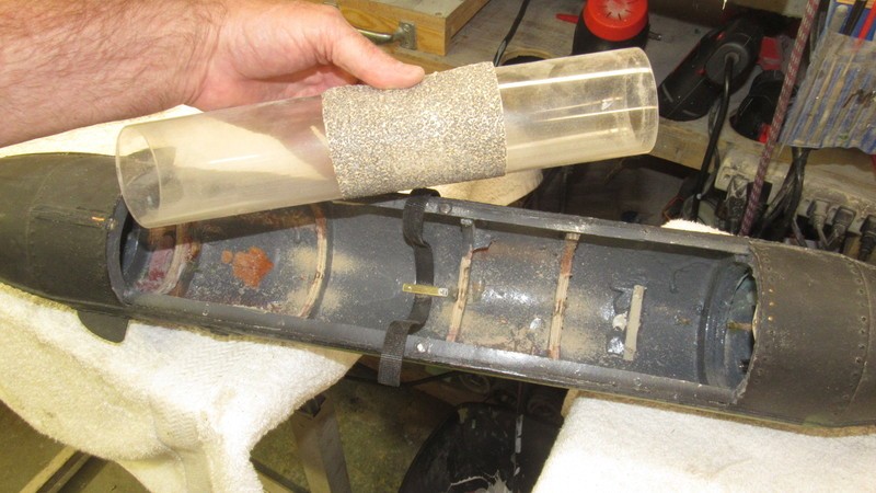
As I ground away the frames to contour I identified the high spots by placing a cylinder, coated with white oil-paint, down on the work, which left white smears on areas of each frame that needed more grinding. This process continued until the WTC motor shaft shared that of the hulls longitudinal axis.
Final shaping of the semicircle indentations in the HUNLEY's frames was done with a scrap length of 2.5” diameter Lexan cylinder (same diameter as the eventual WTC that will be mounted in the hull) used as a form to sand the frames to contour.
Note that I've installed a Velcro strap that will be used, along with an indexing pin (yet to be installed) to register and hold in place the models WTC.
DavidWho is John Galt?Comment
-
The Hunley has forward diving planes, why the need for pitchable propeller?Make it simple, make strong, make it work!Comment
-
David, What size is that shrink tubing you are using on the RX?If you can cut, drill, saw, hit things and swear a lot, you're well on the way to building a working model sub.Comment
-
“HUNLEY had no stern horizontal control surfaces it would have been unmanageable about the pitch axis submerged above any speed where dynamic forces overcame the boats natural pitch stability”.Of the approximately 40,000 men who served on U-boats in WWII, it is estimated that around 28,000 to 30,000 lost their lives.Comment
-
FINALLY! The propeller pitching mechanism has been manufactured, installed, dialed in, and found to work as planned. This illustration is a quick look at its function and the call-outs will help understand the following narrative as I employ proper terms to the various components.
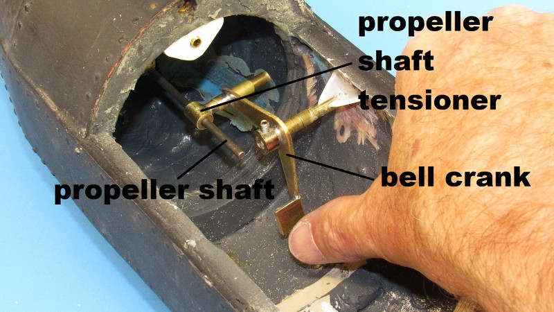
The final configuration differed little from the initial full-scale shop sketch of the propeller pitching mechanism. The only significant change was to adopt an Oilite bearing element against the after propeller shaft length instead of the wire 'cage' I used on my NAUTILUS models. We grow as time marches on.
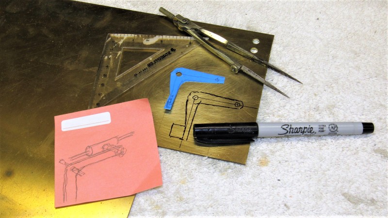
Use of a card-board mock-up bell crank to scull out the proper distance between input and output points in relation to the pivot point. A few of these card-board studies and I had the desired shape and distancing. The mock-up was pulled and used to mark off a thick piece of brass sheet from which the actual bell crank would be manufactured.
Using the card-board mock-up as a stencil to mark off the shape of the eventual brass-sheet bell crank. Note that I've added a big tab at the bottom of the bell crank – this will be eventually bent back ninety-degrees to form a pusher plate against which the pitch servo push rod will act.
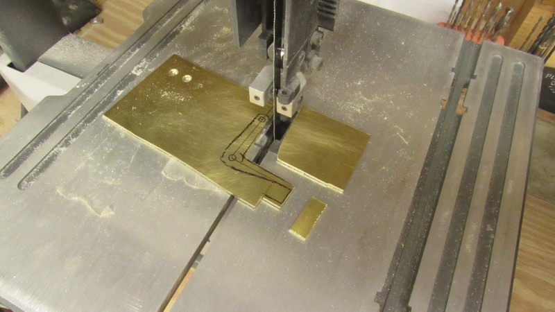
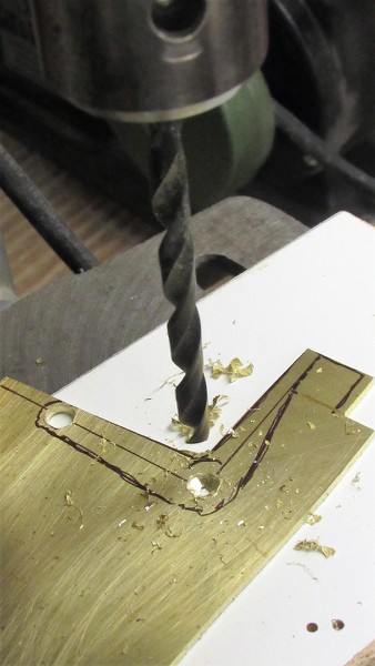
Sawing, boring, and finishing the bell crank.
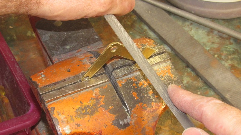
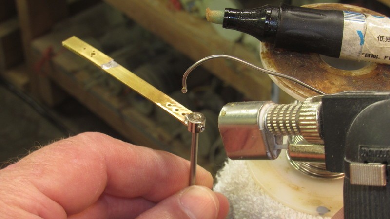
The bell crank features two brass tube bearings. One for the bell crank pivot pin. The other (the one being soldered in place here) for the tensioner perpendicular shaft.
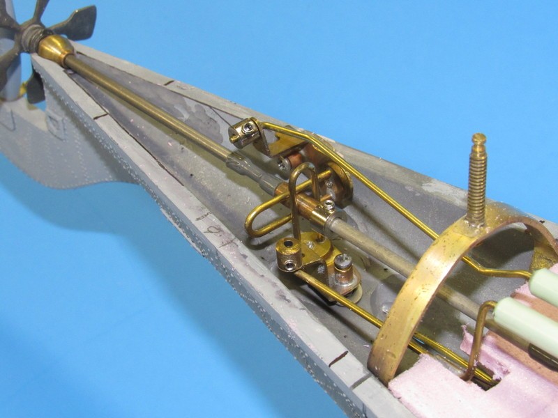
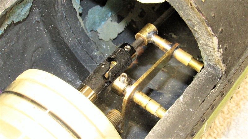
The bell crank is free to rotate about its pivot shaft, and the attached tensioner is free to rotate as the after propeller shaft piece pitches up and down. Note the retaining collar between the hull and bell crank pivot bore. That collar and the removable Du-bro wheel-collar, near the WTC universal, sets the lateral position of the tensioner and insures that the propeller shaft elements do not move laterally, only vertically.
The propeller pitch tensioner not only had to force the after shaft section up and down, it also had to translate as the angle of that shaft changed. This required the tensioner to be support by a perpendicular shaft that would be free to rotate within the bell crank during operation. Here I'm soldering that shaft in place onto the short tube section that would mount the eventual Oilite bearing, seen in background.
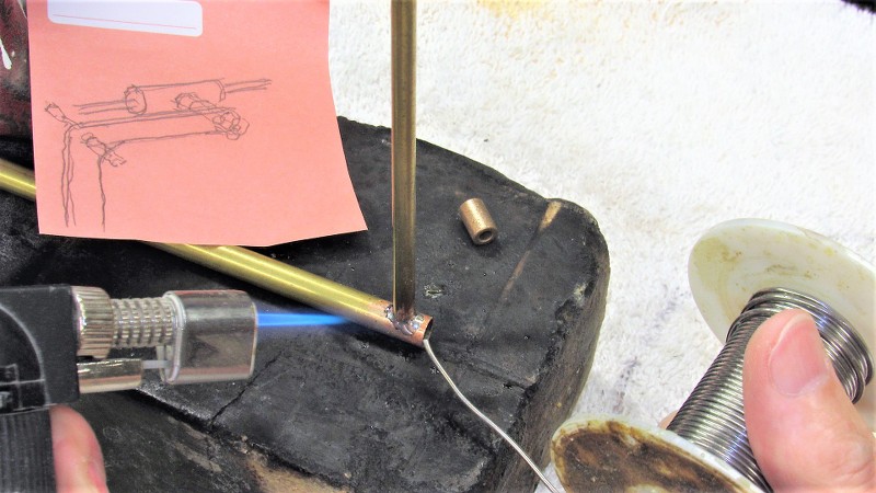
It's my practice to have a pad of post-it-notes in every room of my house – especially the bathrooms! – as I never know when a good/bad idea will pop into my head. I have even, on occasion, jumped out of bed in the middle of the night to jot down something that came to me in my sleep. Here are but two of the many sketches I worked up as I wandered about thinking of how things could go together with the HUNLEY's propeller pitching mechanism.
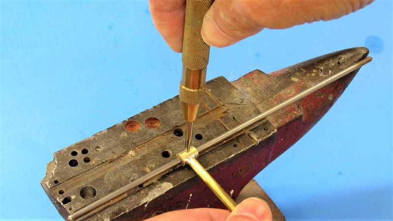
Here I'm sliding a 1/8” bore Oilite bearing into the body of the still-in-work propeller shaft tensioner.
Peening the Oilite bearing in place within the tensioner with the aid of a spring-loaded punch. This is done with a stainless steel length of shaft in place to prevent deforming the bore of the Oilite bearing during this operation.
A bracing gusset atop the hull holds the rudder torque rod tube firmly in place.
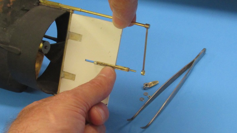
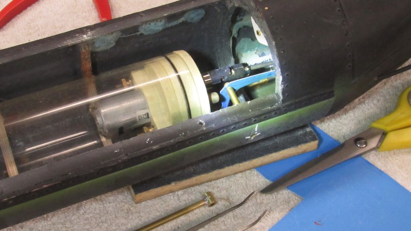
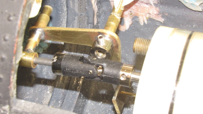
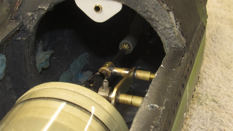
Within the after portion of the HUNLEY's hull you can make out the propeller pitching mechanism: The WTC with output motor shaft made up to a universal joint; to the right the bell crank with attached 'floating' shaft tensioner; and, almost out of sight, the spline with slipped on flexible hose 'universal' that interconnects the forward and after sections of propeller shaft.
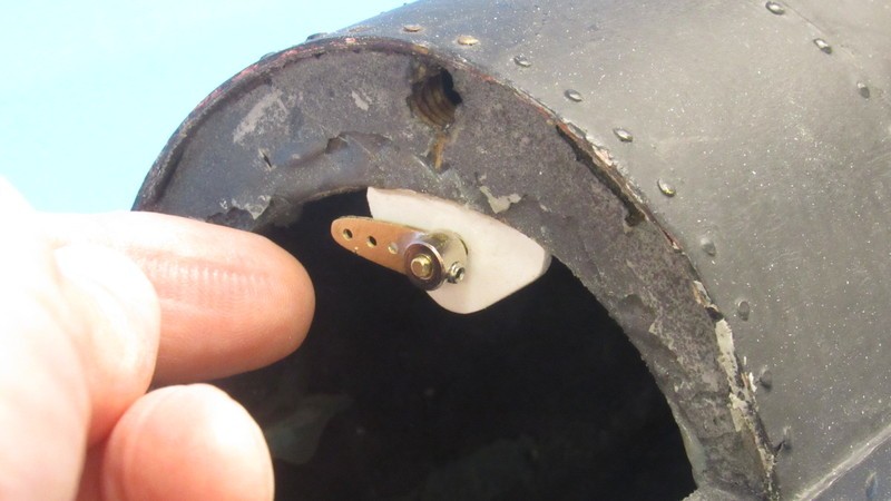
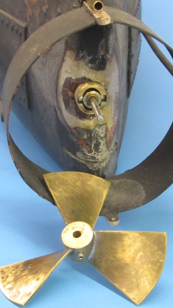
Here's a good shot of the installed propeller pitching gimbal. Note how the foundation that girdles it has been scalloped out top and bottom to permit the gimbal to swing up and down. You can just make out the press-fit Oilite bearing within the gimbal that provides a low friction bore through which the propeller shaft rotates. That Oilite bearing also offers a low friction surface to the transverse loads as the propeller shaft swings up and down.
 Who is John Galt?
Comment
-
How did you make the gimbal, specially those trunnions?Make it simple, make strong, make it work!Comment
-
David, when you solder such items as the bellcrank, do you silver solder them or do use typical 60/40 solder?Comment


Comment