today's work

Collapse
X
 
  • Time
  • Show
Clear All
new posts
  • He Who Shall Not Be Named
    Moderator
    • Aug 2008
    • 12253


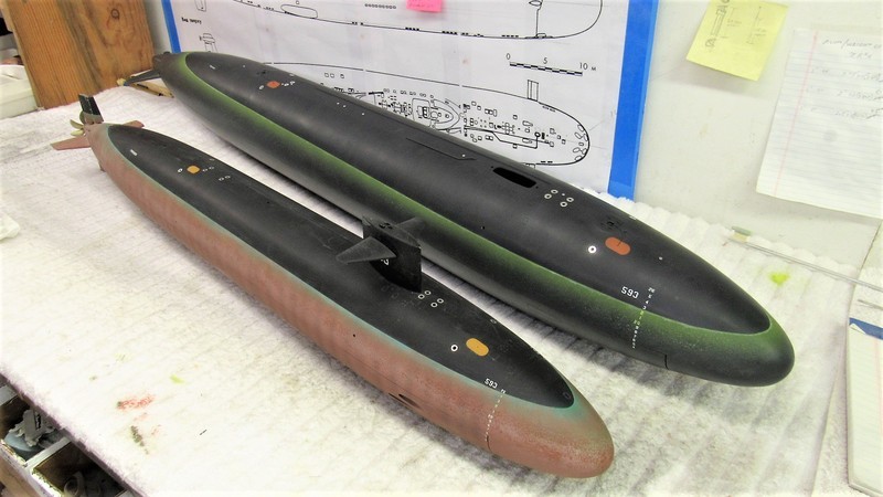
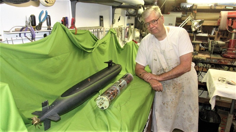
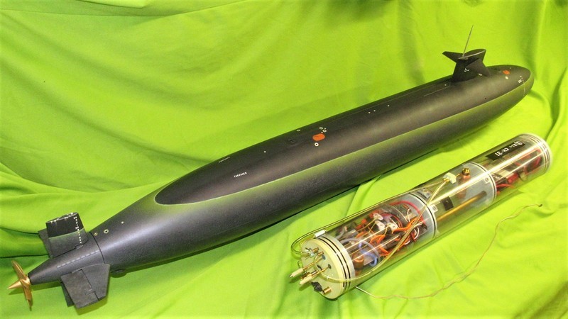
    While working on the 1/72 THRESHER I remembered that I had to get my old Mat Thor 1/96 THRESHER model dressed up and tested for the upcoming Groton sub-run next month. So, during the touch-up painting – chronicled later – I pulled the 1/96 model off the wall and addressed it while I still had wet paint left over from the 1/72 model paint touch-up and weathering.

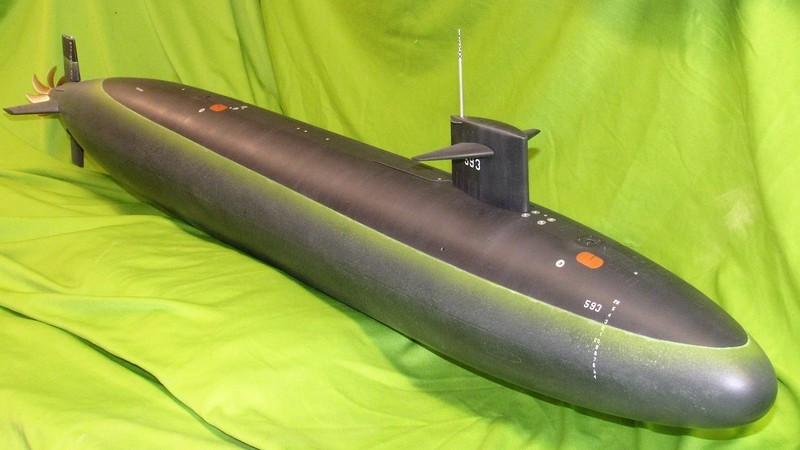
    This picture clearly shows that I don't have a clue as to the THRESHER's anti-foul color at any time during its service life. Was it all black, or did it sport anti-foul red from waterline down/from centerline down? Beats the hell out of me; I simply don't know! Anyone out there who can give me a solid answer, I would appreciate hearing from you.

    Different yards, different ways of doing things. Confusion is the by-product.


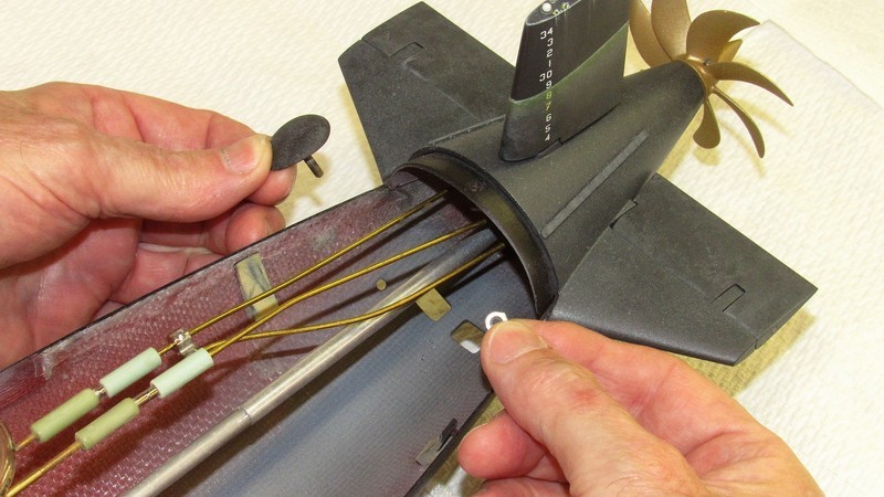
    During all that detailing and handling my grubby finders stained the work. So, before committing to the markings, touch-up painting, and well flattened DuPont ChromaClear clear-coat the entire model – including all its removed appendages – was scrubbed with soapy water, rinsed, and dried and hit with a tack-rag to (hopefully) reduce its static charge, a move to limit accumulation of dust between the cleaning and the other operations.


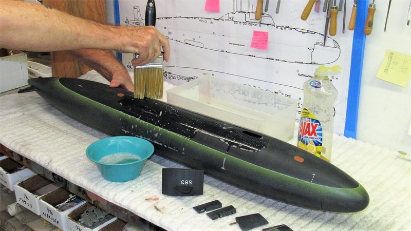
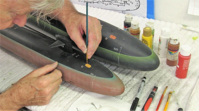
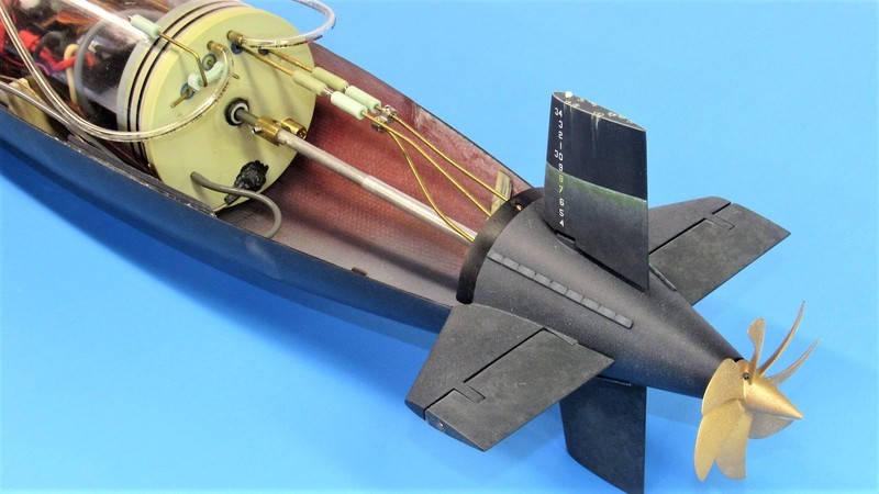
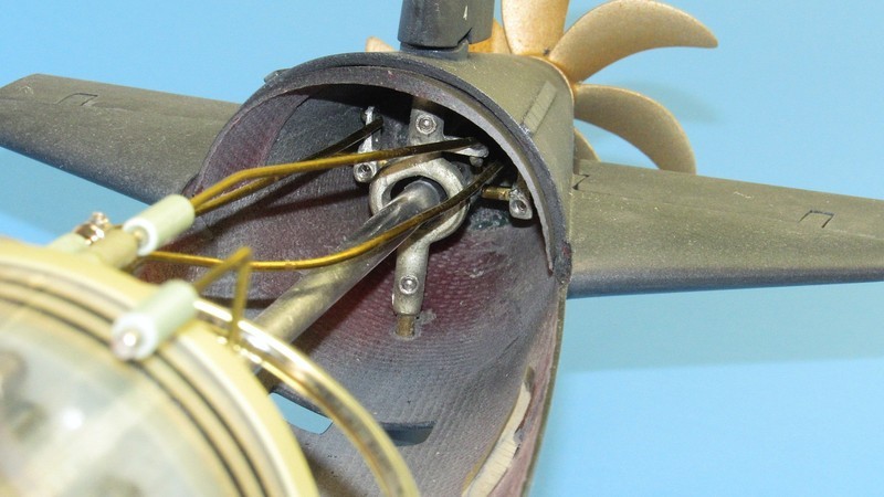
    Four rows of cathodic protection – owing to the dissimilar metals of brass and steel hull at the stern – in the form of sacrificial Zinc anodes, were highlighted by scrubbing onto them brownish-white oil paint applied with a brush, then rubbed in with a paper-towel.


    The objective was to suggest mild oxidation of the Zincs as a consequence of galvanic action (two dissimilar metals, sea water, all in close proximity = battery).


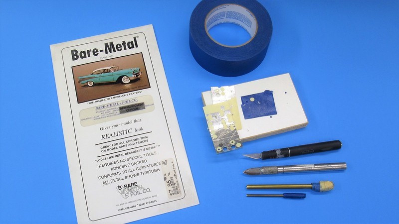
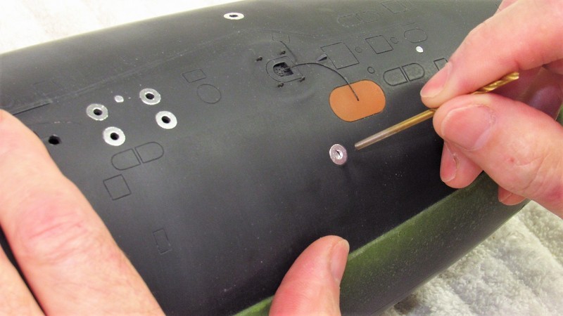
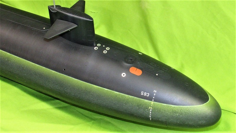
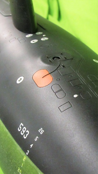
    Nothing looks like shiny metal like shiny metal. In those modeling situations where you need that 'look', a self adhesive aluminum foil is often the medium of choice. Such is the case with the THRESHER's deck mounted main ballast tank vent (MBTV) retaining rings, and disc shaped compartment salvage covers. As a practical matter most boats that go out on patrol have these items painted the same flat black as the other structures. However, I have seen pre-commission and post-overhaul shots of boats that have these items unpainted.


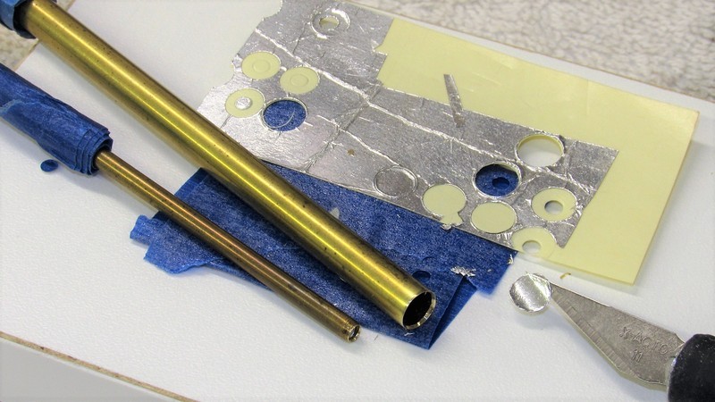
    Bare Metal Foil is my go-to product for self-adhesive foil. They offer several shades of Aluminum. And, as they say in their advertising: “It looks like metal because it is metal”. Can't argue with that!

    You either cut out the desired shape of foil while it's still attached to its backing; or you lift an over-sized piece of foil off the backing, place it on the model, burnish it down, and then cut to outline and pull away those portions not needed. On this job, which required simple circular pieces of foil, the cutting was done off-model with the aid of appropriately sized punch-cutters.


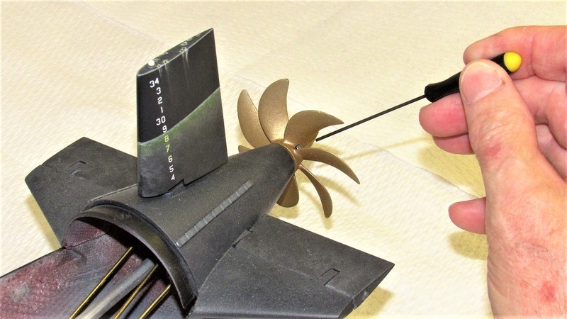
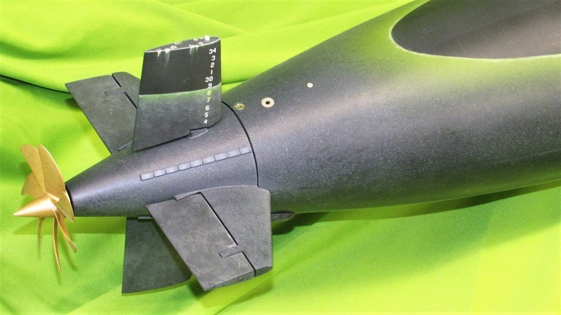
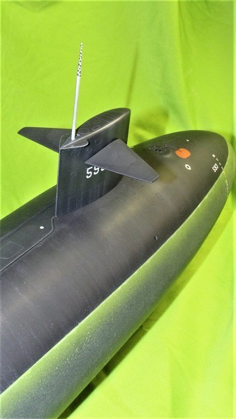
    The reason I take every opportunity to make things on an r/c submarines topside structures stand out is, visibility! When operating submerged I have to see something. And metallic items, or garish 'international orange' escape marker-buoys, hull and draft numbers, and even weathering – help one to make out the submerged models location and attitude. Vital. If you can't see it, you can't drive it!

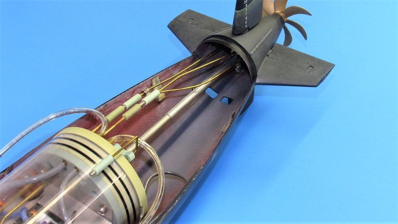
    Here I'm refining the open hole of the MBTV by pushing the shank end of a drill bit into the hole which forces the foil to fail and punch through the hole, leaving a crisp opening where air can quickly vent in or out of the hull as the model submarine transitions back and forth between surfaced and submerged trim.


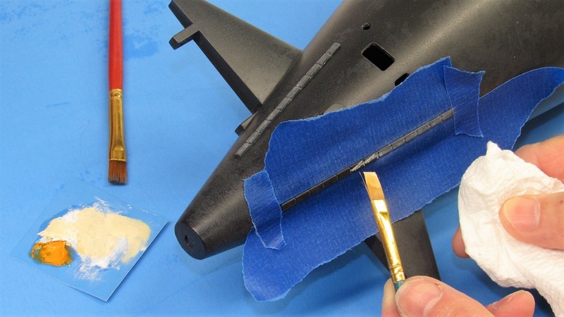
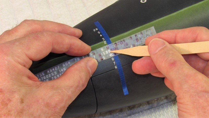
    Use of dry-transfer markings produces crisp, clean markings of the desired size, font, and color. But, the process does demand of you correct use of lay-out tools to place each marking in the correct spot, with proper spacing between the markings.

    Woodland Scenics, their Model Graphics division, produces an all encompassing sheet of white transfers suitable for almost any US submarine. You want MG747 45-degree, USA No. GOTHIC-WHITE. Sizes of the numbers are suitable for both hull numbers, and draft numbers in 1/192, 1/96, 1/72, and 1/32.


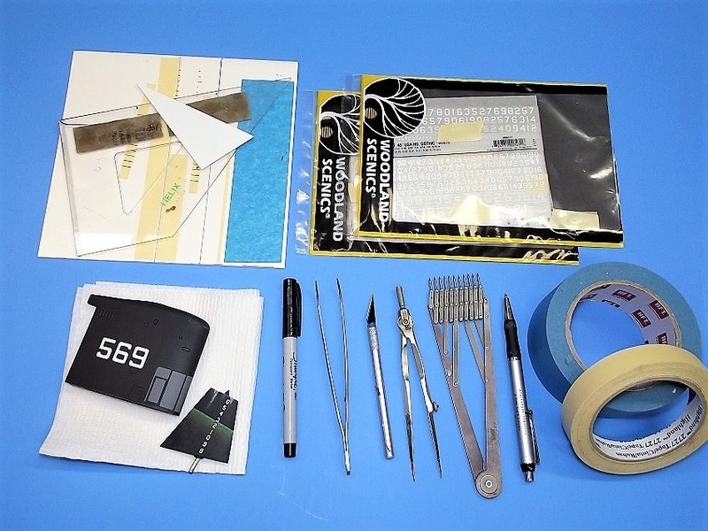
    Care is taken to employ a masking tape guide to help keep the individual markings in correct location on the model as well as in correct spacing from one another. The wax-like markings, are available in many different fonts, sizes, and colors. US Navy numbers and letters on ships are usually white and are a block type font. The marking itself is bonded to a carrier-film. The marking is transferred to the work by placing the carrier-film – which is transparent enough for you to see through it and the marking you will press onto the model – where you want it, then pressing over that marking with an embossing tool to force the sticky marking to break its weak bond to the carrier-film and stick to the models surface. That accomplished, the carrier-film is pulled away, leaving the marking on the model.


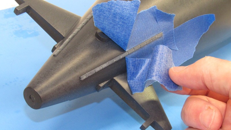
    Nice thing about self-stick dry-transfers is that if you make a mistake (here I've gotten the '9' and '8' slightly out of alignment, so they had to go) its an easy matter to lift the offending marking off the model with masking tape. The inherent weakness of the marking is countered later when the model is given a heavy clear-coat, which goes a long way in making the dry-transfer marking more durable.


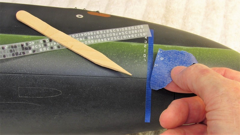
    Though there are commercially available 'burnishing tools' out there, it's been my experience that the pointy end of a stick – or sharpened end of a popsicle-stick – will do the job equally well. A slightly blunted point works best for the smaller sized transfers.


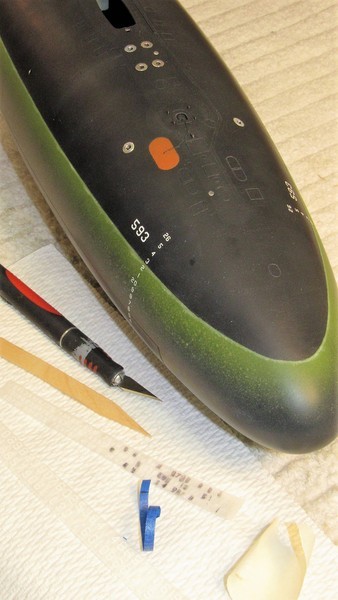
    Here I'm using some very watered down green to slightly discolor the just applied white dry-transfer draft numbers just below the models waterline.


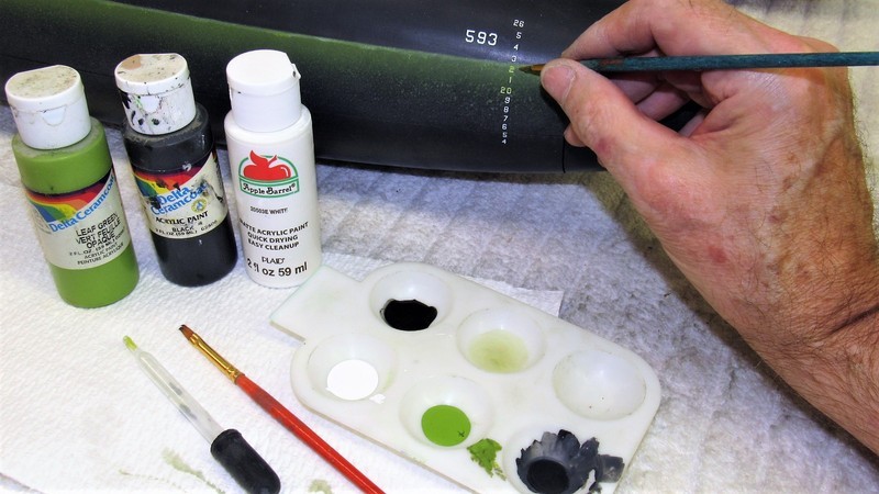
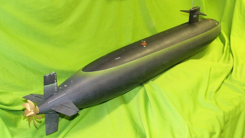
    While the water-soluble acrylic paint was out I did some touch-up paint repair work to the 1/72 THRESHER, as well as to a 1/96 THRESHER I have to get ready for the upcoming Groton Sub-Run. Color matching submarine models is pretty easy: black and white to get any gray you need, some green, and the three primary colors which give you the ability to mix any color or shade to suit the job.

    Who is John Galt?

    Comment

    • SubDude
      Captain
      • Dec 2019
      • 803

      Always love the wealth of information here and this came right at a time when I needed it. Thank you sir.

      Comment

      • He Who Shall Not Be Named
        Moderator
        • Aug 2008
        • 12253

        Originally posted by RCJetDude
        Always love the wealth of information here and this came right at a time when I needed it. Thank you sir.
        Thank you. Just passing on what other taught me.

        David
        Who is John Galt?

        Comment

        • He Who Shall Not Be Named
          Moderator
          • Aug 2008
          • 12253


          Well, Fred's big 1/72 THRESHER is about done. As you may recall, this is a re-build necessitated by a broken horizontal stabilizer and massive failure of filler used to fair in the longitudinal edges of the upper and lower hull halves. All the painting and weathering completed, time had finally come to assemble the control surfaces, propeller, anchor, and sail to the hull proper. As is my practice I endeavor to make the models appendages removable, secured with mechanical fasteners where ever possible. So, final assembly was accomplished in less than an hour.

          Here the resident goof-ball attempts to stare down the camera. Moron. Don't know why I keep him around. He should be busting tables somewhere!


          The two planes were inserted into the sail and their linkage made up. Then two machine-screws were run up through the hull to hold the sail in place. You can make out the bell-crank, which terminates in a magnet, projecting into the hull. Later a push-rod makes up to the bell-crank magnetically – the means of angling the planes for fine depth control when running the submarine below the surface.

          Within the upper hull you can make out the snorkel induction mechanism. The float acts to shut off the induction line to the SubDriver (SD) when the model submerges. On the surface the float drops, opening the snorkel, permitting the SD to draw air from the surface to blow the ballast tank dry.


          Each stern plane had its own bell-crank and push rod – the two ganged together, as you see here, to work as one. The rudders, on the other hand, were joined together through a common 'yoke' that permitted the centrally running propeller intermediate drive-shaft to pass through that linkage without interference.

          The propeller secures to the back end of the propeller shaft with a set-screw. The forward end of the propeller shaft makes up to a Dumas type coupler which in turn makes up to a Dumas dog-bone universal fitting at the after end of the aluminum intermediate drive-shaft.

          The forward ends of the stern plane and rudder push rods terminated in magnetic couplers that interfaced with couplers projecting from the motor-bulkhead of the SD.


          Starting with the THRESHER/PERMIT class, American attack submarines started placing their anchor aft, in the free-flooding 'mud-tank'. This radical move made because of the new, all encompassing use of the bow for the active and passive sonar elements. There just was not room in the bow for the anchor, haws pipe, windless, and chain locker. Also, they did not want rattling chain and a clanking anchor and stem making the sonar guys deaf.

          The anchor, a resin part cast with an embedded threaded stud, was secured against the side of the lower stern with a single nut.


          See how the SD and control surface push rods make up magnetically. Note the centrally running intermediate drive-shaft.


          Who is John Galt?

          Comment

          • SteveNeill
            Commander
            • Apr 2020
            • 315

            I enjoyed that very much. Entertaining but you should keep him around IMHO.

            Comment

            • JHapprich
              Captain
              • Oct 2017
              • 712

              That brass-ring soldered dogbone is brilliant! Will copy and paste! You just saved me machine work!

              Jörg

              Comment

              • redboat219
                Admiral
                • Dec 2008
                • 2735

                Originally posted by JHapprich
                That brass-ring soldered dogbone is brilliant!

                Jörg
                Which picture is that?
                Make it simple, make strong, make it work!

                Comment

                • JHapprich
                  Captain
                  • Oct 2017
                  • 712

                  The one after " see how the sd and control surface...". To link two independent rods. I would have milled such thing from massive brass

                  Comment

                  • redboat219
                    Admiral
                    • Dec 2008
                    • 2735

                    Oh I see, the soldered wheel collars. Like an 8.
                    Make it simple, make strong, make it work!

                    Comment

                    • JHapprich
                      Captain
                      • Oct 2017
                      • 712

                      Yes! A simple yet versatile device.

                      Comment

                      • He Who Shall Not Be Named
                        Moderator
                        • Aug 2008
                        • 12253

                        Click image for larger version

Name:	DSCN0068.JPG
Views:	273
Size:	43.8 KB
ID:	152544Click image for larger version

Name:	DSCN0193.JPG
Views:	268
Size:	58.8 KB
ID:	152545Click image for larger version

Name:	DSCF3449.JPG
Views:	265
Size:	58.3 KB
ID:	152546Click image for larger version

Name:	DSCF3725.JPG
Views:	265
Size:	45.0 KB
ID:	152547Click image for larger version

Name:	DSCF3457.JPG
Views:	254
Size:	41.2 KB
ID:	152548Click image for larger version

Name:	DSCF4504.JPG
Views:	268
Size:	49.3 KB
ID:	152549Click image for larger version

Name:	DSCF5290.JPG
Views:	263
Size:	57.1 KB
ID:	152551Click image for larger version

Name:	DSCF5298.JPG
Views:	265
Size:	55.0 KB
ID:	152552Click image for larger version

Name:	DSCF5278.JPG
Views:	257
Size:	46.4 KB
ID:	152550
                        Originally posted by JHapprich
                        Yes! A simple yet versatile device.
                        Other variations on the theme.

                        And you can go stupid-simple and employ only one oversized wheel-collar to mash several push rod elements into one.

                        Who is John Galt?

                        Comment

                        • JHapprich
                          Captain
                          • Oct 2017
                          • 712

                          Thank you for the many pictures! Concerning one single collar, exactly that i want to replace Click image for larger version

Name:	20210706_191430.jpg
Views:	238
Size:	89.7 KB
ID:	152560Click image for larger version

Name:	20210704_152514.jpg
Views:	237
Size:	82.6 KB
ID:	152559Click image for larger version

Name:	20210704_152505.jpg
Views:	238
Size:	98.7 KB
ID:	152558Click image for larger version

Name:	20210704_153308.jpg
Views:	248
Size:	100.6 KB
ID:	152557Click image for larger version

Name:	IMG-20210813-WA0008.jpeg
Views:	239
Size:	53.0 KB
ID:	152561

                          Comment

                          • JHapprich
                            Captain
                            • Oct 2017
                            • 712

                            The big silver wheel-collar for the rudder has to go. Same for a long pushrod for the forward planes. Last picture shows 2 variants for a forward diveplane linkage

                            Comment

                            • JHapprich
                              Captain
                              • Oct 2017
                              • 712

                              Ill post details when i finish my report on my Zero Bubble Mike.

                              Comment

                              • He Who Shall Not Be Named
                                Moderator
                                • Aug 2008
                                • 12253


                                The last couple of months has kept me busy readying some of my r/c model submarines for the two big events of the year, both occurring during the month of September. Now that those obligations are out of the way, I continue my work (and this WIP report) on several in-progress modeling jobs. This installment I re-join the effort to restore a HUNLEY model sent to me by a friend who wants to get it fully functional and back into the water.

                                The real Confederate HUNLEY was a privateer built to sink Union blockading ships during the American Civil War. The craft, though lost with all hands on its last mission, did in fact record histories first successful engagement between submarine and ship – the actual HUNLEY has since been found, salvaged, and currently undergoing restoration.

                                This model, though flawed as to proportion and detail, is a close enough representation of the HUNLEY as to warrant my full attention and efforts to get it into presentable shape as to look and function. So, with my shop restored to proper order I took the long suffering HUNLEY model down off the wall and did a quick survey of what had been accomplished (yeah... it's been that long!), and what work remained to be done to get this beast operational.

                                I had already worked out the gimbal mechanism for the propeller (as the HUNLEY had no stern horizontal control surfaces it would have been unmanageable about the pitch axis submerged above any speed where dynamic forces overcame the boats natural pitch stability); and installed the rudder control-rod (henceforth properly referred to as the 'rudder torque rod') bushing. So, last night I manufactured the rudder and got a good start piecing together that very Rube Goldberg'ian rudder control linkage. Could the Southern marine Architects have made a more complicated means of banging that big rudder around??...

                                Damn!


                                Long before the salvage of the HUNLEY we had a very good look at what the actual boats rudder mechanism looked like, in the form of a beautiful, miniature painting by the period Civil War chronicler, Conrad Wise Chapman.

                                His pencil studies and eventual painting of the HUNLEY – presumably representing the boat either awaiting a mission on a pier, or undergoing a post sinking restoration (there were several such disasters during the boats career) – became the sole document to accurately illustrate the arrangement and function of the HUNLEY's rudder mechanism. I recommend you check out this site for more on the Artists and this particular painting: Conrad Wise Chapman - Wikipedia

                                (You old-time r/c model airplane guys will recognize the HUNLEY's rudder mechanism as one very much like that used on single-channel model aircraft that employed a rubber-band powered actuator, charmingly referred to as an, 'escapement', to position the models rudder (often the only r/c function aboard the model aircraft... those were the days!).


                                The Internet is a wonderful resource; a quick find about the possible (and now 'actual', owing to the recent discovery of the actual boat) workings of the rudder mechanism garnered me photos of well done models, and illustrations identifying the key components of the mechanism. With that information in hand I started proofing my ideas through a series of shop sketches – that process helping me segregate out the loopy ideas from the sound ones. Here I've sketched out how I would integrate a brass tube rudder bushing to a Sintra plastic sheet rudder.

                                (Sintra is a trade-style for a polyVinyl Chloride plastic sheet with hard faces, and a foam core – a useful model-building medium).

                                Note the use of two soldered brass extensions to strengthen the attachment of plastic to metal. Pasted to the corners of the sketch are copies of rudder mechanisms pulled from various sources – these guiding me as I created my own practical rudder mechanism.


                                The 3/32” o.d. brass tube -- sized to sleeve within it a 1/16” diameter brass rod – with its two soldered brass batons was CA'ed to the leading edge of the Sintra rudder after cut-outs for the batons and central bail-bolt slot is cut out with an #11 knife blade.

                                A big virtue to Sintra is that its thin hard surfaces and soft inner core are easily cut and require little pressure to penetrate. Yet this low density material is very resistant to torsional loads; is relatively heat stable; and takes to adhesive, cohesive, primers and paints beautifully.

                                Here I'm using the CA-baking soda to adhere the parts and fill gaps between brass tube and batons and the rudder proper.


                                After each application of CA and baking soda, just as soon as the mass hardens (which takes only seconds), I knock down the high spots with file and a lot of elbow-grease. Eventually I'll coat over the CA-baking soda filler with touch-up putty and wet sand the entire assembly, getting it ready for primer and paint. But, that's for later.


                                David
                                Who is John Galt?

                                Comment

                                Working...