Welcome to our forums. For the best in R/C submarine kits, components and accessories, be sure to visit the Nautilus Drydocks
If this is your first visit, be sure to
check out the FAQ by clicking the
link above. You may have to register
before you can post: click the register link above to proceed. To start viewing messages,
select the forum that you want to visit from the selection below.
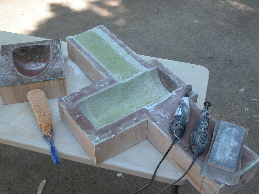
Oh, wait a minute... just found these shots that make me a liar: Ellie and I did a job for MIT in the early 2000's that made use of quick and dirty hard-shell tools:
Likely some grad-students got a grant to buy some of Skip's vacuformed kits and used them to validate a Paper. Too bad they did not bother to learn how to prepare ABS/Polystyrene for painting. I was not involved in this study.
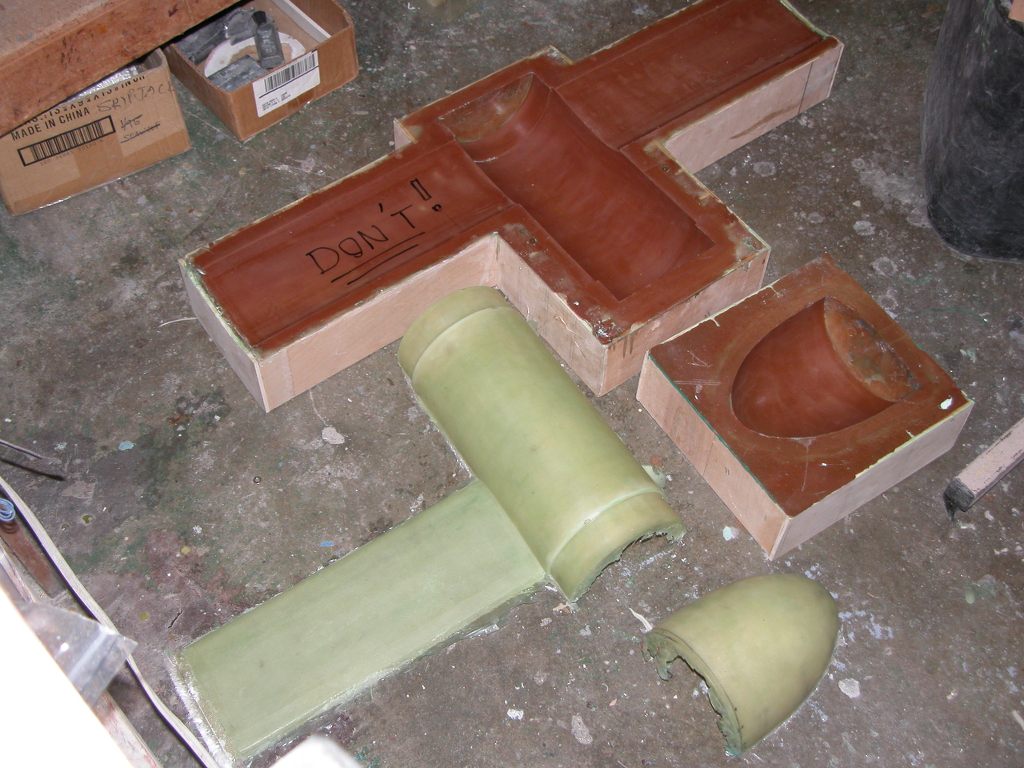
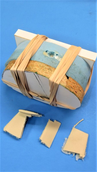
After popping the tail-cone GRP halves out of the tools I set them aside and readied the tools for lay-up of 10-ounce fiberglass cloth to form the first full hull. This hull to proof the tools before I sent them off to the production site, and they would also provide me a personal play-toy down the road.
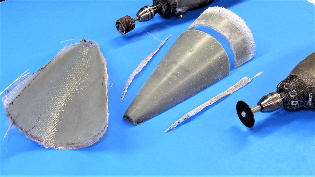
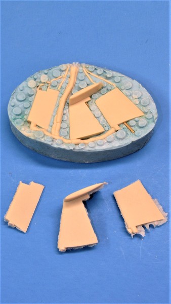
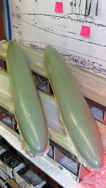
The eventual tail-cone master started life as these two GRP halves, here being trimmed so they can be assembled and then worked into a useful 1/96 STURGEON tail-cone master. More on that horror show later.
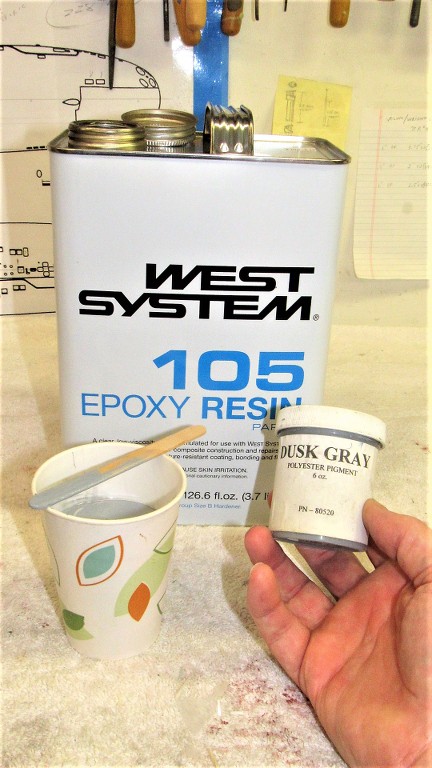
A side note. The West System laminating resin I use produces a semi-clear finish. I prefer an opaque gray -- easier to see flaws in the work. So, I dope the resin side of this two-part epoxy system with a gray pigment. It don't take much!
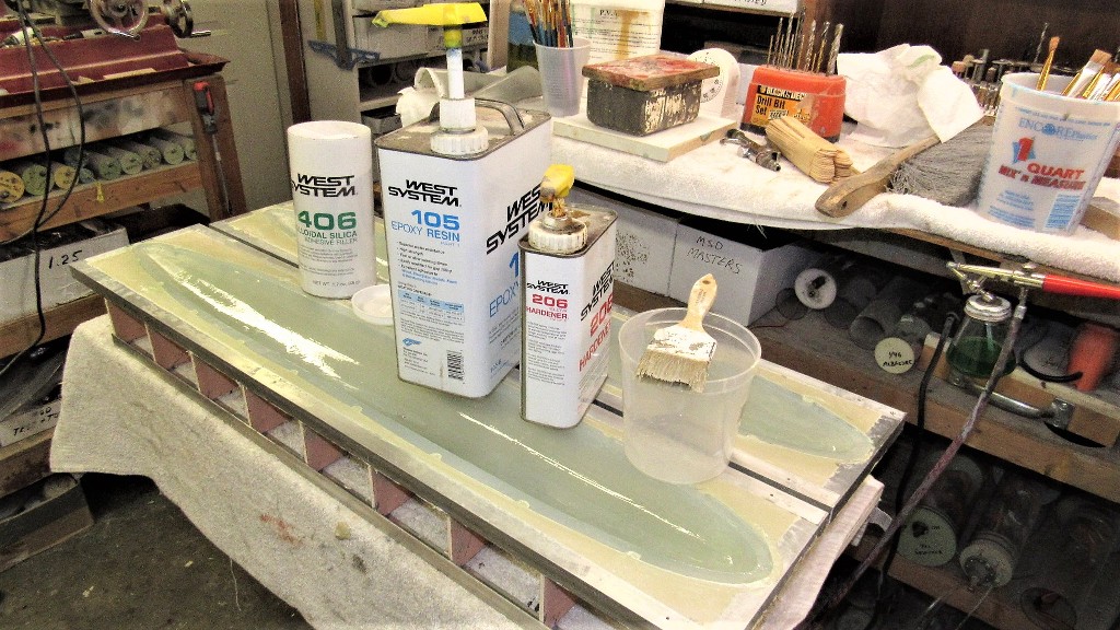
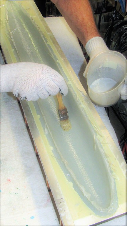
The two hull halves would be laid up in four laminates. The first is a 'gel-coat', a thickened laminating resin used to fill any tight corners (such as the three projecting transducer fairings atop the upper hull) and serve as a leveling buffer between the weave pattern of the glass cloth and the surface of the model parts. Following the gel-coat on went, in quick succession, three laminates of 10-ounce glass cloth.
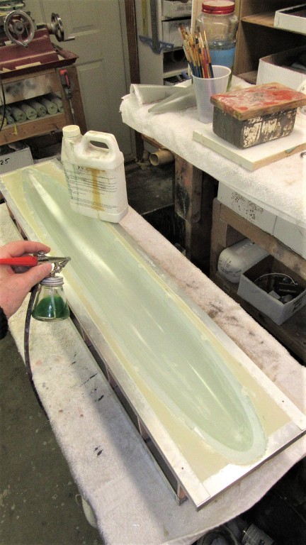
Nice thing about using RTV silicon rubber as the contact surface between tool and GRP part is the simplicity of the part-release system. Simply a heavy (multiple) coating of polyvinyl alcohol (PVA). This barrier prevents chemical degradation of the rubber through contact with the epoxy laminating resin chemistry. The water soluble PVA is easy to mix, apply, and clean-up. I typically put down five coats with the air-brush, hitting the work with a heat gun between coats to quicken the process.
Gel-coat is home made by mixing up some laminating resin neat, then doping it with something like micro-balloon, talc, mill powder, or colloidal silica (my favorite) to thicken the mess. This produces a high fill, non sagging coating within the tools cavity.
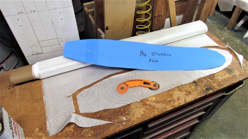
I had prepared a template to guide my pizza-cutter as I cut out the pieces of 10-ounce fiberglass cloth needed for the two hull tools. Gel-coat and three plies of cloth would be enough to get me the 3/32" wall thickness I want on these size submarine hulls.
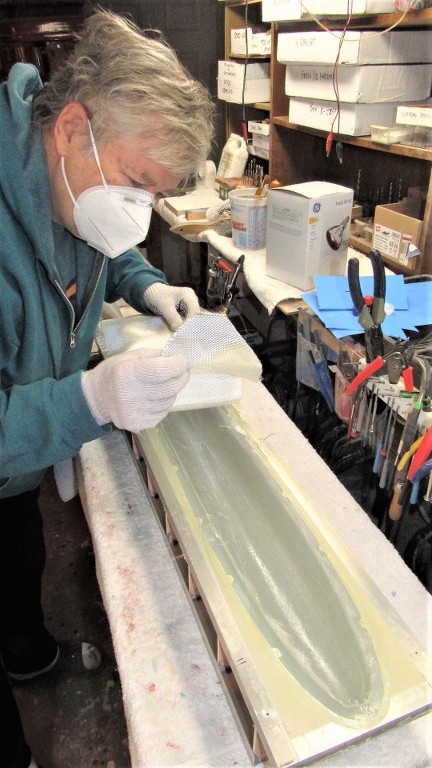
Once the gel-coat hardened I laid in the first laminate of glass cloth and saturated that with catalyzed epoxy laminating resin. I took care to wick out excess resin before it gelled -- the thicker the hull, the more water it displaces, the more ballast tank you need to compensate for that extra buoyancy when the above waterline structure submerges.
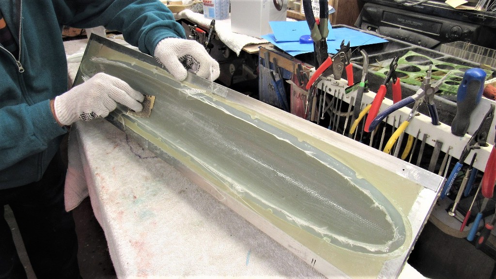
After one laminate cures I sand it to knock down any clumps that would prevent proper wetting out of the next laminate.
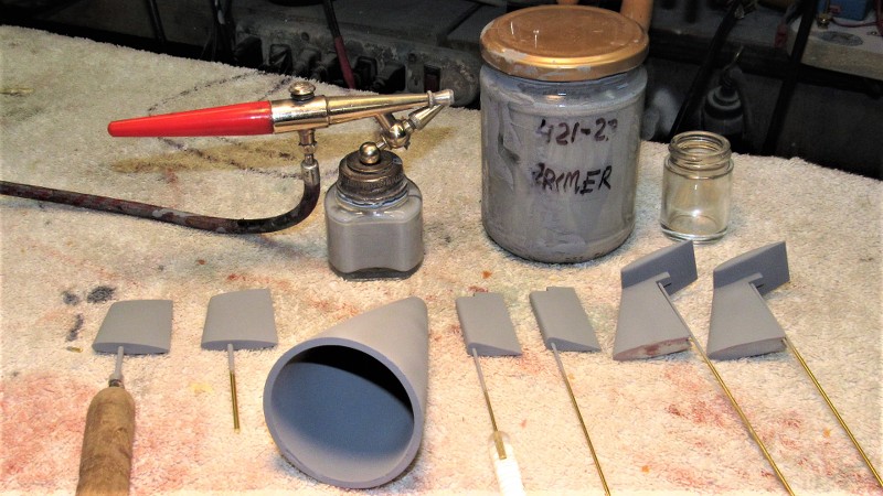
Meanwhile work continued finishing up the rubber tools so I could cast copies of the stern planes, horizontal-vertical stabilizers, and rudders.
I have often wondered why you cast a separate tail cone and not leave it an integral part of the grp layup
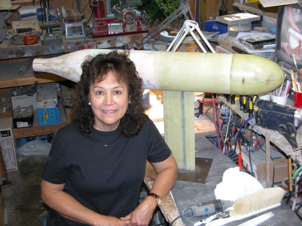
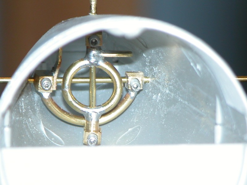
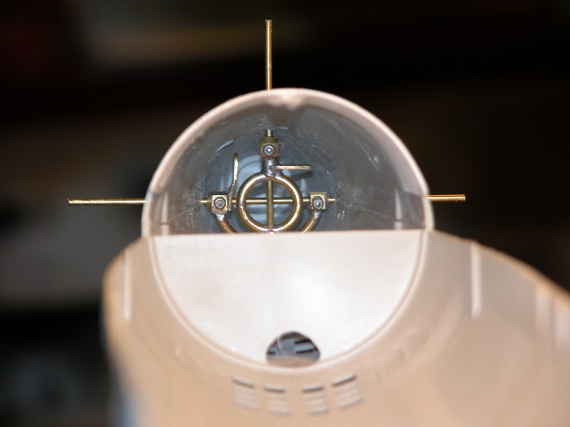
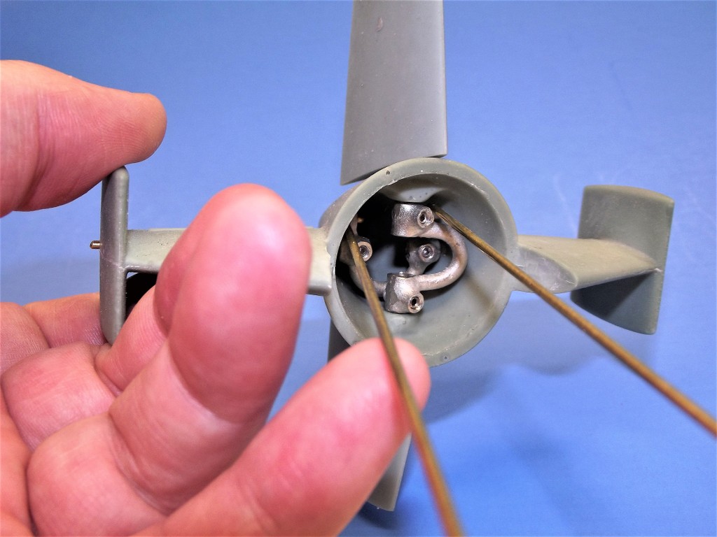
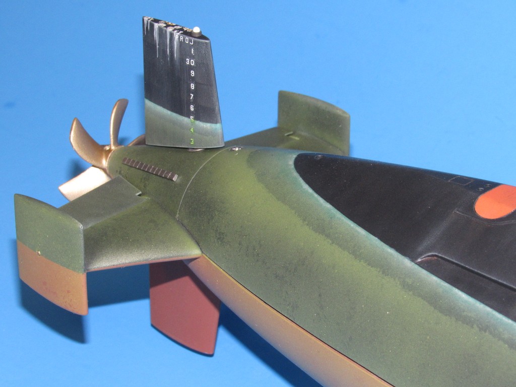
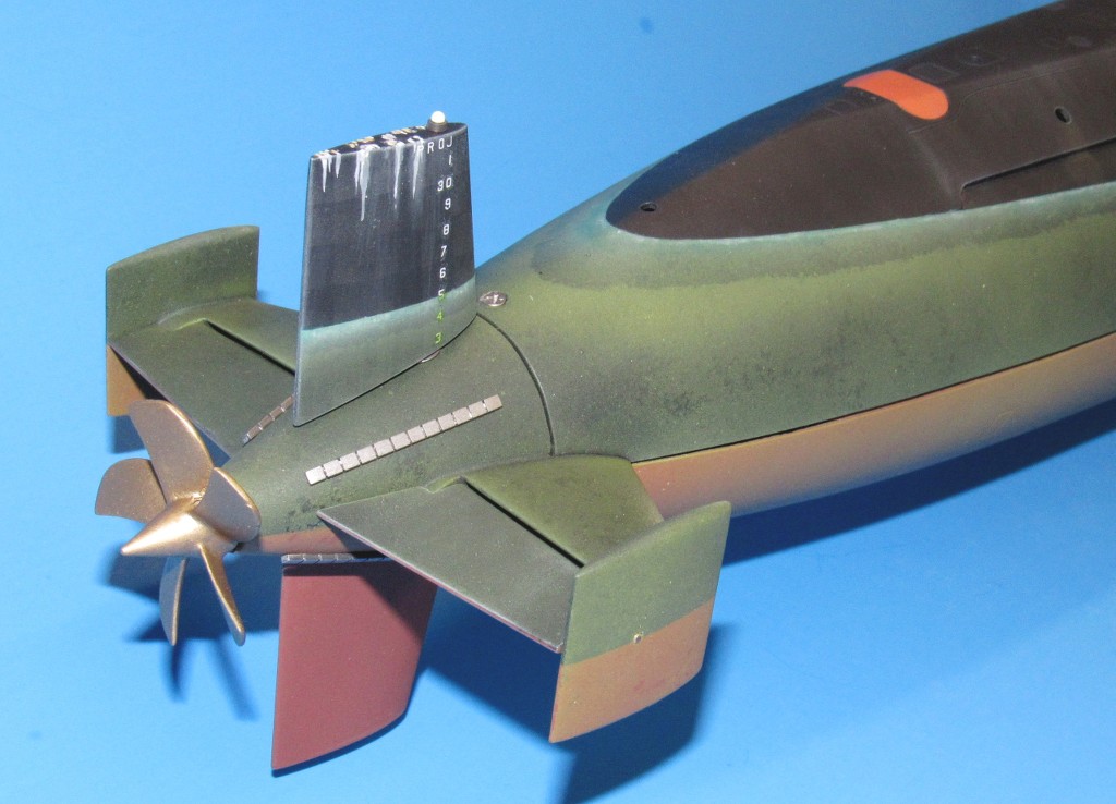
I do this to provide the customer a pre-assembled, worked out structure where all the hard parts are already installed and tested. Like this 1/96 BLUEBACK kit tail-cone:
You sir are an enabler of the common mouth breathing kit assemblers....shame shame shame ..all hail David the Good, helper of the weak and down trodden unwashed masses.
thank you
You sir are an enabler of the common mouth breathing kit assemblers....shame shame shame ..all hail David the Good, helper of the weak and down trodden unwashed masses.
thank you
Bite me you patronizing, smooth-talking, sardonic, squid-throwing, bacon munching, white creature from the great northern wastes! Why do I put up with you people?!
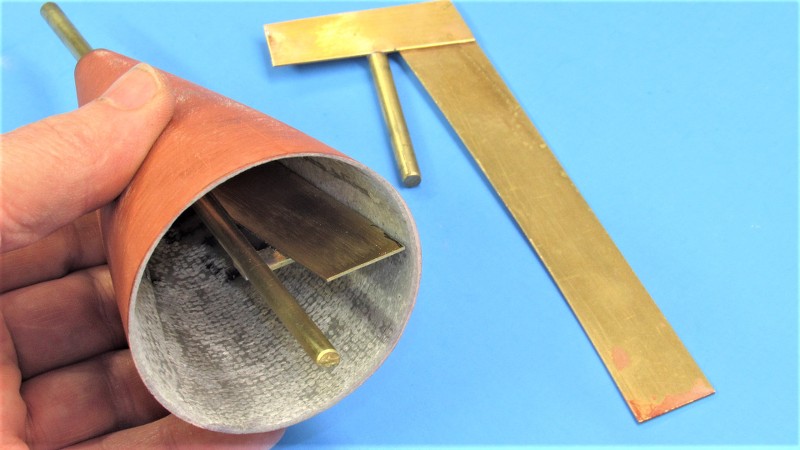
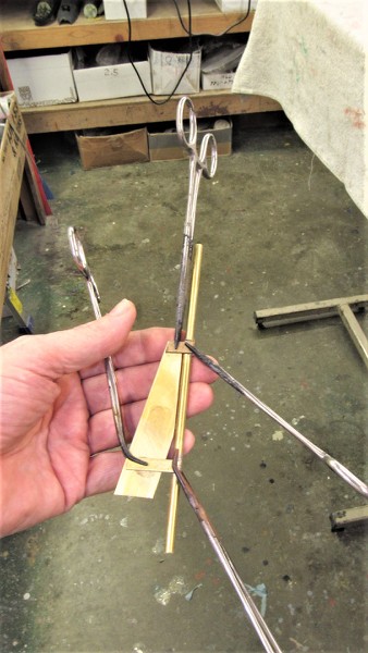
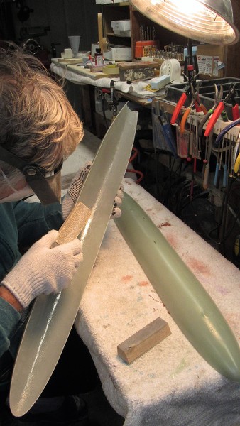
I laid up an upper and lower after section of hull -- that would become a master for the tail-cone which in turn would be used to make a rubber tool for resin casting -- from the completed hull tools. These were bonded together and brought to a perfect round of uniform wall thickness with the aid of two screeding blades.
The two GRP partial hull pieces ready for trimming.
Best way to cut cured GRP is with a carbide cut-off wheel. Safety glasses, respiratory gear, and gloves a necessity here. The trimming out of the way the two halves were tack glued together with CA and glass tape placed on the inside seams and saturated with the epoxy laminating resin. When cured two 3/32" i.d. Oilite bearing were installed in the stern and potted in place with more epoxy laminating resin -- this representing the eventual stern tube that would accept production tail-cone propeller shafts. On this master the centered bearings became the axial reference line about which the screeding blades would swing.
When cured two 3/32" i.d. Oilite bearing were installed in the stern and potted in place with more epoxy laminating resin -- this representing the eventual stern tube that would accept production tail-cone propeller shafts. On this master the centered bearings became the axial reference line about which the screeding blades would swing.
The two screeding blades, how they were made and used:
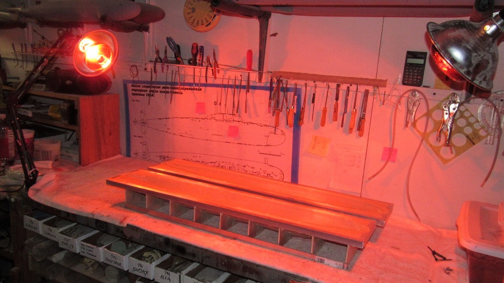
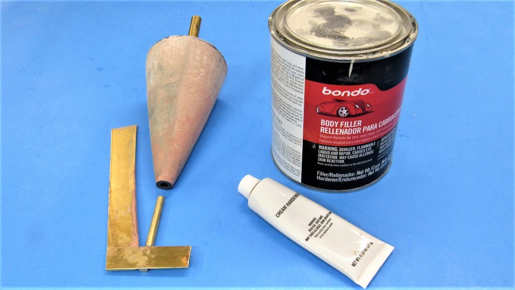
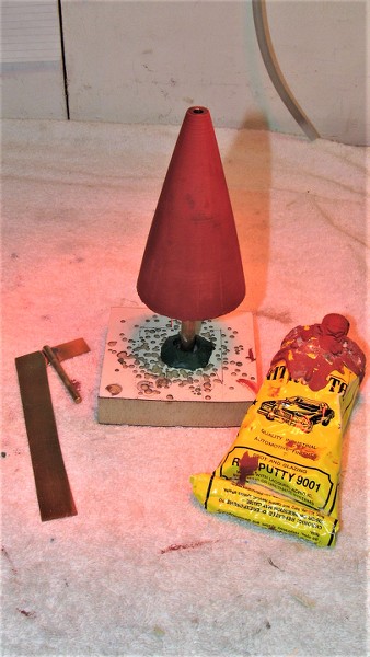
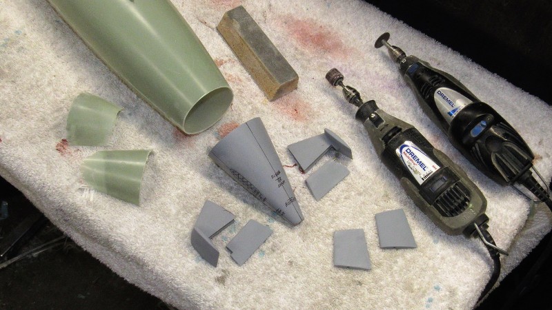
The gross build up of the tail-cone master wall was done with cheap-ass Bondo. The fine tuning was done with air-dry touch-up putty. This work went very quickly as I employed a heat-lamp to accelerate the cure of the filler, and drying of the putty.
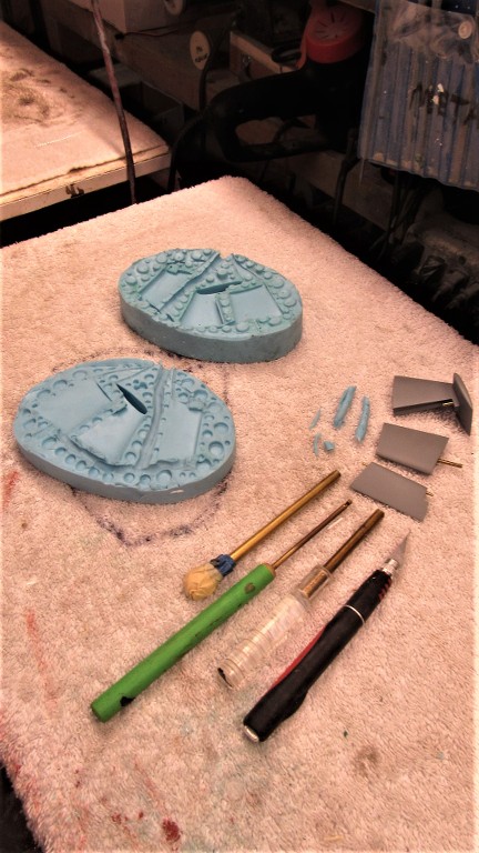
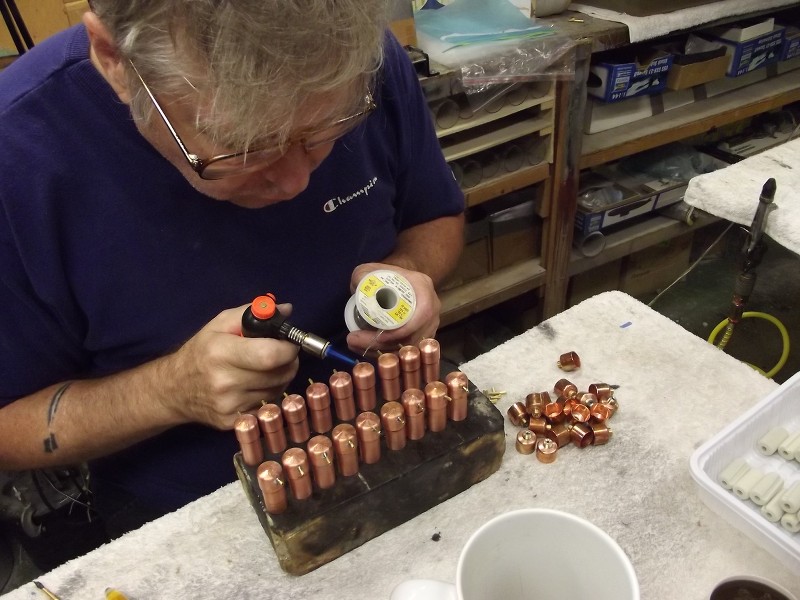
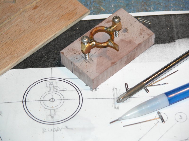
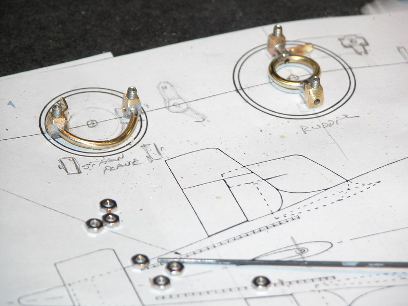
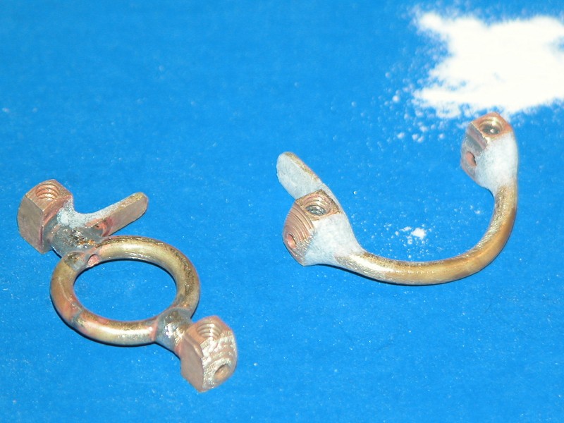
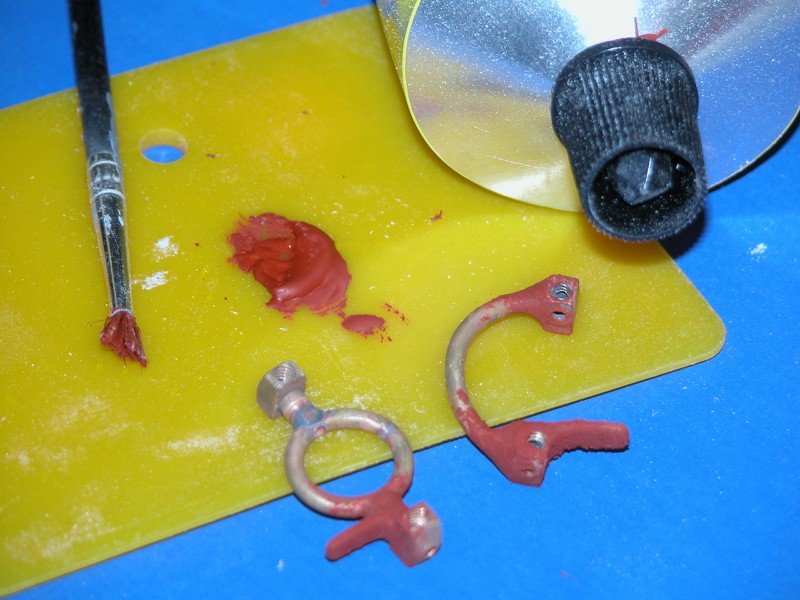
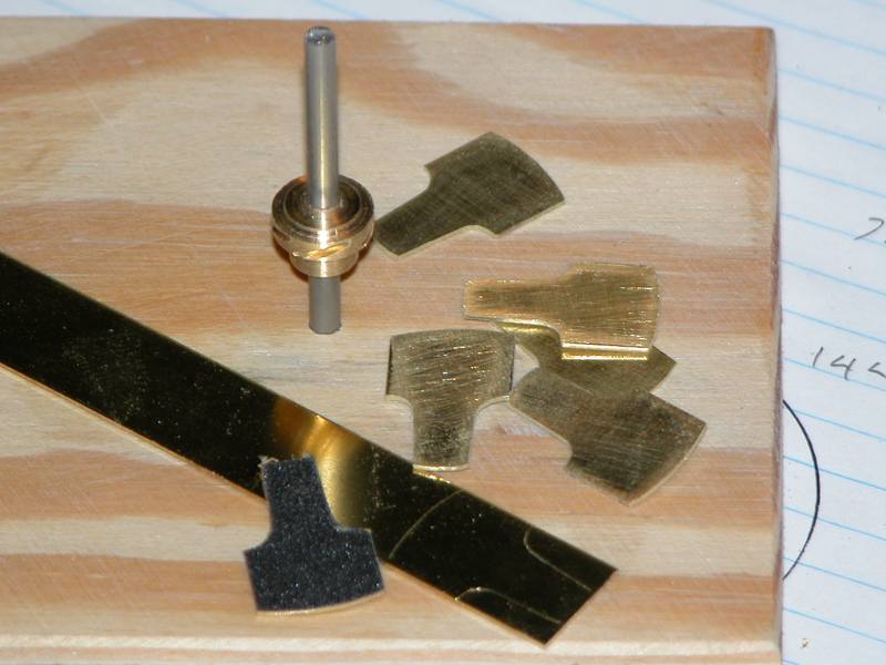
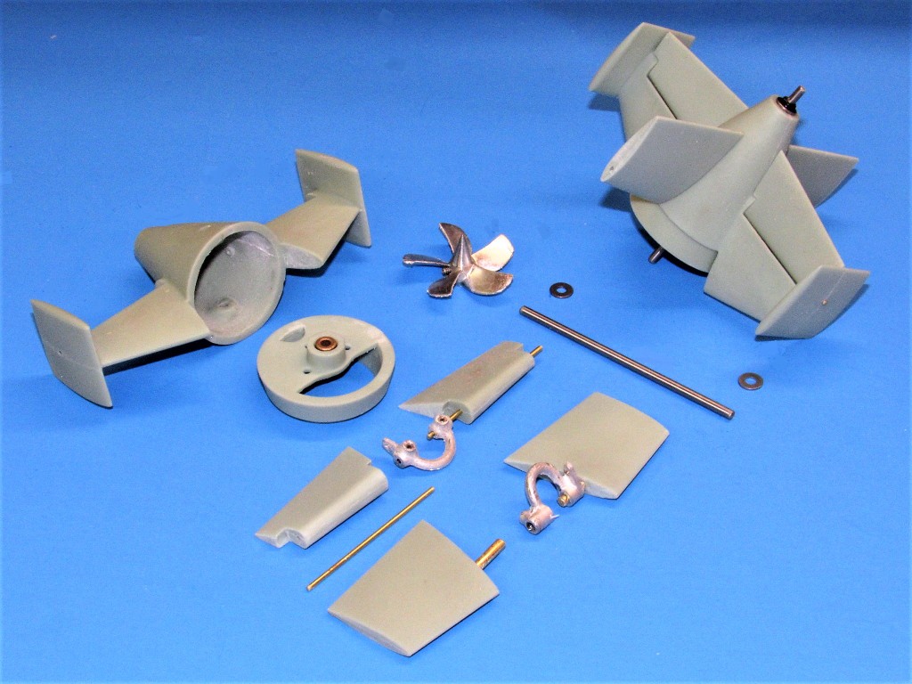
Meanwhile I cast the appendages needed to deck out the tail-cone master.
David!
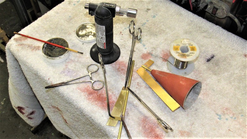
It's certainly a pleasure to watch your work each day and see the methodical way and methods you use on the parts that you build. I see by the some of the above photos that you are doing some soldering!
I am about to embark on some brass work myself on the HL Hunley. What solder and flux do you find that works the best for you in fabricating brass parts? There is a lot of structural frame work around the stern on this boat, and the 3D printed parts are ok for a static model, but not for the actual stress's of RC operation!
Thanks David! As always we do appreciate your help, and respect your view points!!
Rob
"Firemen can stand the heat"
"Perfection is our goal. Excellence will be tolerated"
David
It's certainly a pleasure to watch your work each day and see the methodical way and methods you use on the parts that you build. I see by the some of the above photos that you are doing some soldering!
I am about to embark on some brass work myself on the HL Hunley. What solder and flux do you find that works the best for you in fabricating brass parts? There is a lot of structural frame work around the stern on this boat, and the 3D printed parts are ok for a static model, but not for the actual stress's of RC operation!
Thanks David! As always we do appreciate your help, and respect your view points!!
Rob
"Firemen can stand the heat"
"Perfection is our goal. Excellence will be tolerated"
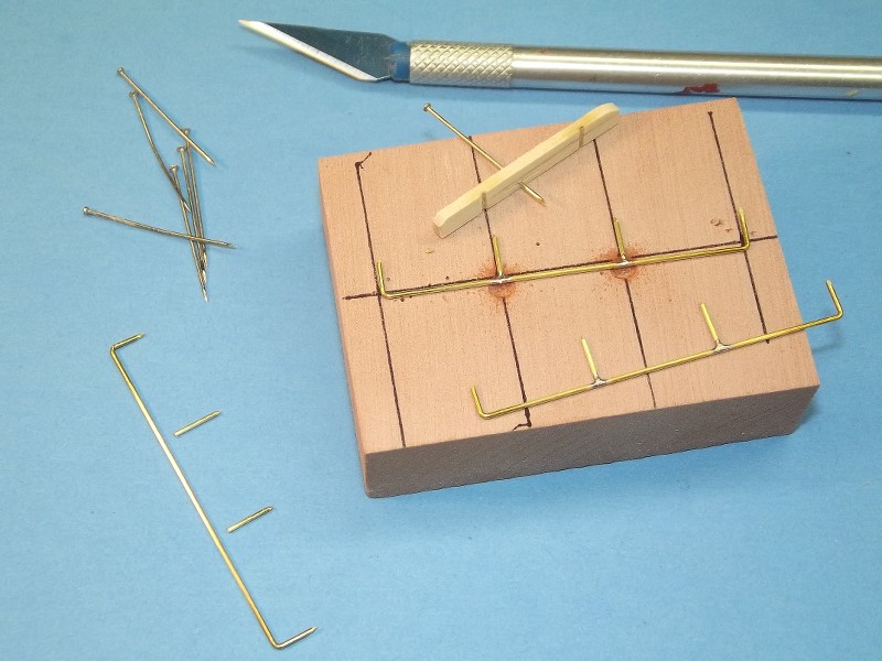
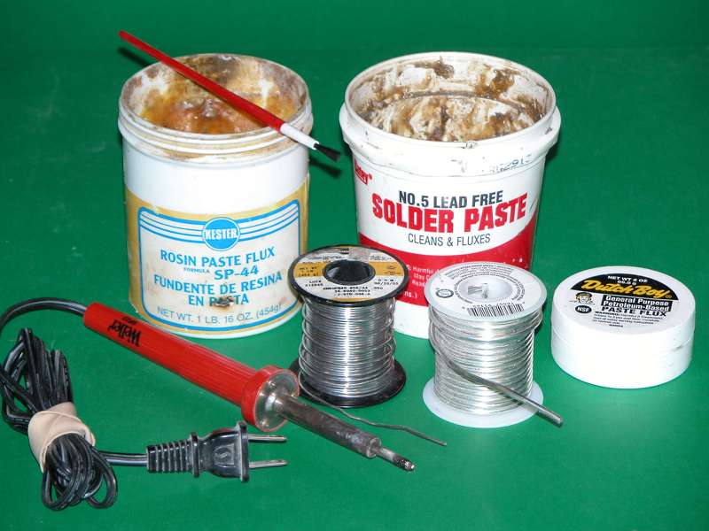
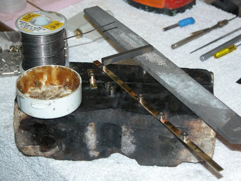
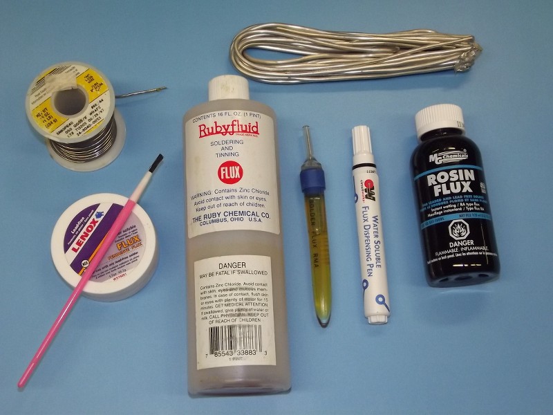
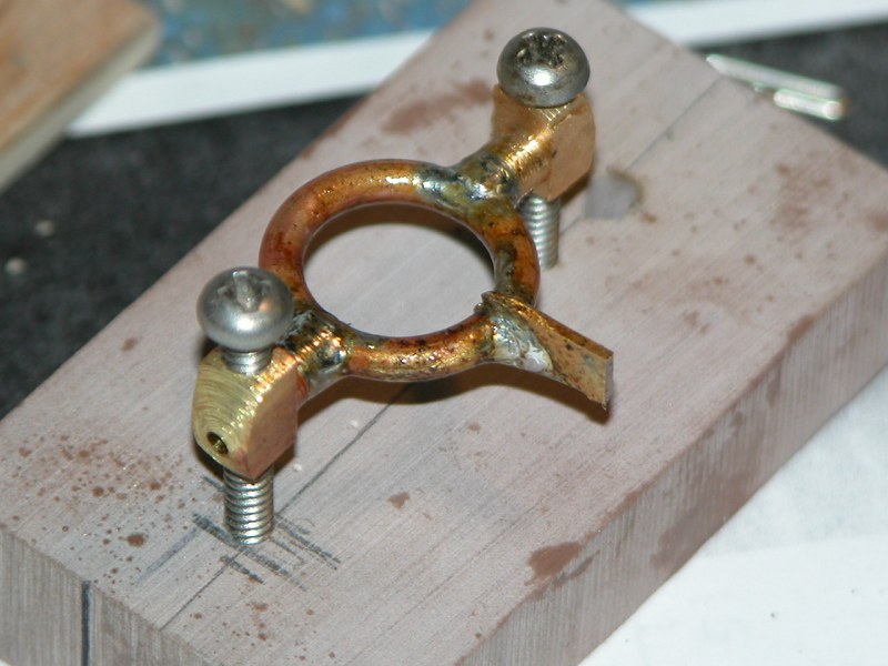
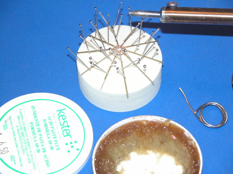
60/40 Tin/Lead does it for me. But you are also well served using that dumb-ass non-lead solder the greenie-whinnies are now pushing down our throats. What you're doing does not require the strength of silver solder or brazing. Cheap, nasty 35 Watt iron and an acid flux is all you need for this job.
90% of the job is how well you jig things up for soldering. Soldering is adhesion -- think the job through before you lift a finger.
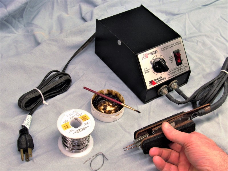
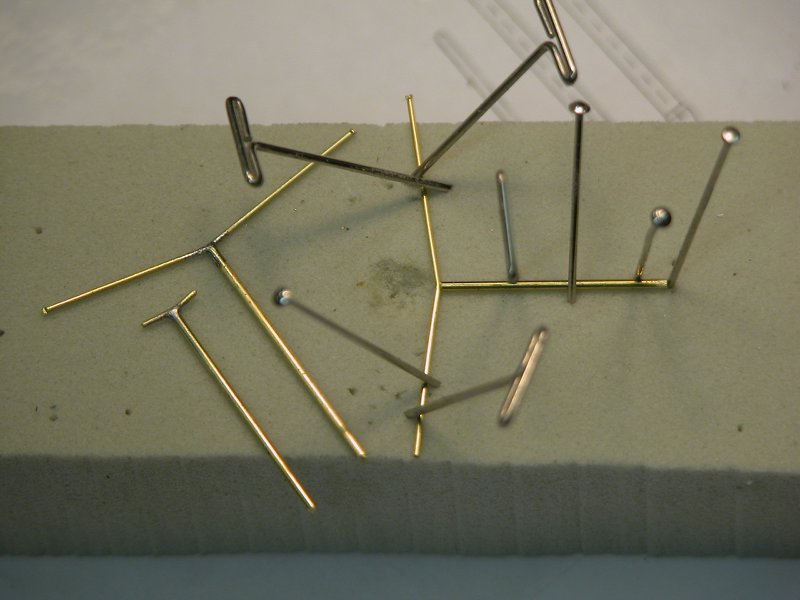
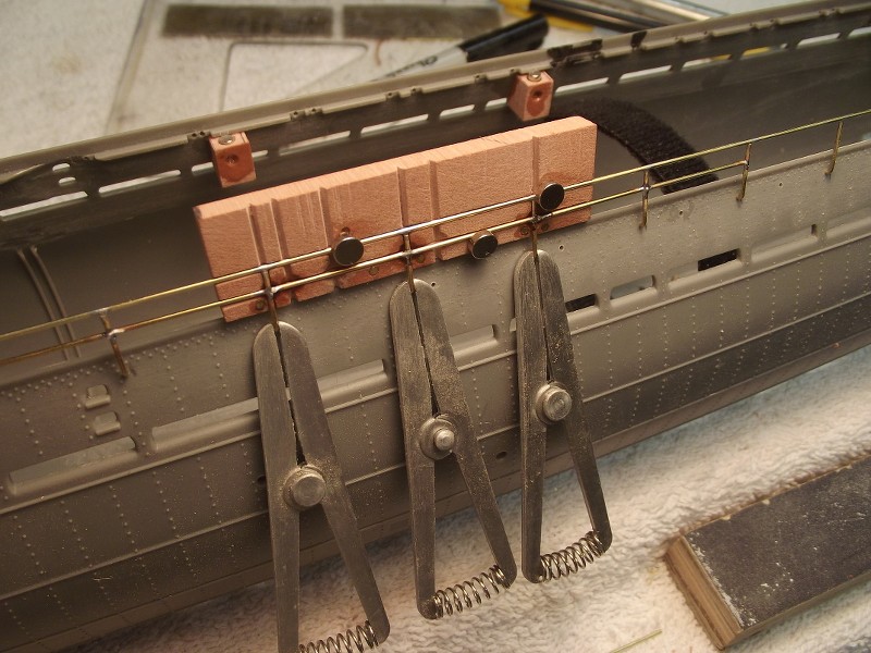
The trick is to control the heat so you don't melt adjoining work. Heat-sinks are your friend, as well as securing devices like hemostats, wet fingers, and gravity.
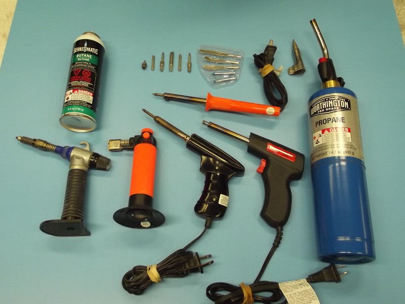
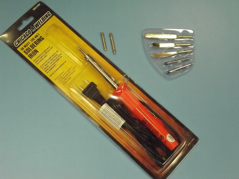
Look at all the happy horse-**** below. If anything warrants amplification, let me know and I'll bore you to tears with what I know about the tools, techniques, and consumables involved.
I really think you have just about covered the subject of soldering. Well done, and THANK YOU for taking the time to put up the photos with you explanation on how to!!
Rob
"Firemen can stand the heat"
"Perfriction is our goal. Excellence will be tolerated"
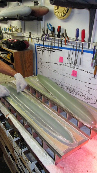
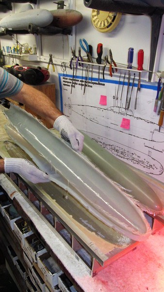
I gave the two laid-up GRP hull parts three days to cure hard in their tools, then popped them out. Though eventually I'll use these hull halves to make my own 1/96 STURGEON r/c model submarine play-toy, their function here is to affirm a good fit to the separate tail-cone master I'm working up -- that tail-cone master eventually used to make a rubber tool from which cast resin tail-cone parts would be produced.
Grabbing some of the above-flange glass fibers I yanked and pulled the laid-up fiberglass hull half clear of the mother-mold, the part still clinging to the glove-mold that gave it shape.
Clear of the mother-mold I'm demonstrating the utility of the glove-mold: I'm peeling it away (glove-like, duh!) from the GRP part. Deep draft, even undercuts, are easily side-stepped during part extraction owing the the flexibility of the glove-mold -- can't do this with a hard-shell type tool!
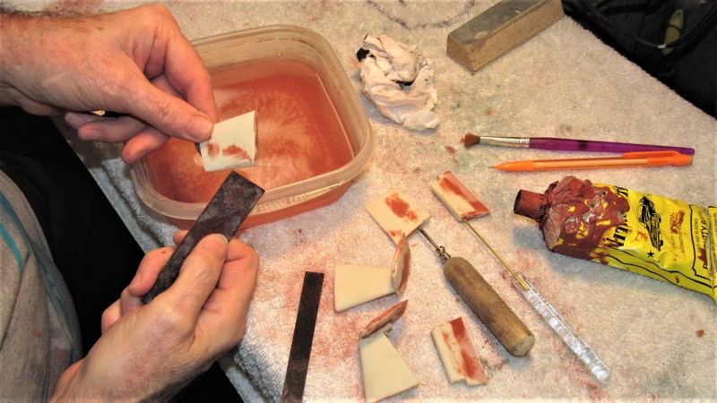
The previously applied part-release coat of PVA still clinging to the GRP parts was easily removed by soaking the hull halves in water which dissolved the PVA, revealing the smooth, highly detailed gel-coat surfaces of the parts. A quick scribing with an abrasive pad soaked in a slurry of cleanser and water, a good rinse, drying, and the parts are ready for adhesives, putties, fillers, and primer.
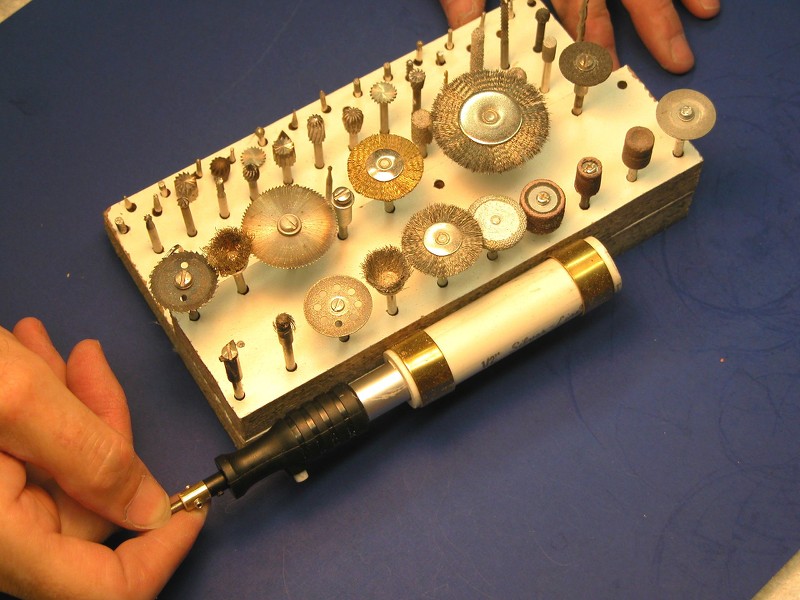
The ideal tool for cutting GRP -- keep in mind you are cutting GLASS!!! -- is an abrasive cutting tool, typically a sacrificial carbide wheel, diamond wheel, or Tungsten/Carbide/diamond reciprocating blade. I opt for the simple, cheap, and easy to acquire ablative cut-off wheel.
On this rotary tool caddy, in foreground, third from the left, is a very thin blade diamond wheel -- perfect for separating GRP parts when you need to minimize material lost to kerf. To the extreme right are two abrasive cut-off wheels -- good for removing flash and excess glass from the parts flange-line.
Here I'm get'n medieval on the excess glass. This is an abrasive cut-off wheel, free-handed. The work goes quickly, but raises a cloud of glass fiber and resin particles. This type tool is the way to go as even tool-steel, and your typical 'Japanese saw', or hobby razor-saw will be dulled to uselessness in only a few strokes if you use them on GLASS!
Note the precautions I'm taking to protect my lungs, eyes, and pinkies. Glass is glass and it will bite your ass if you don't take care!
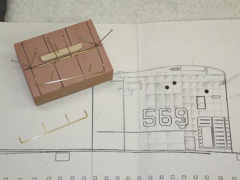
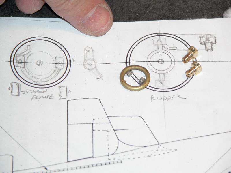
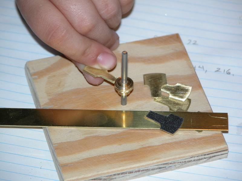
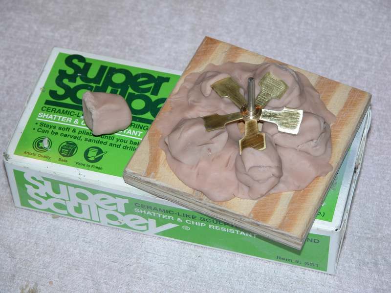
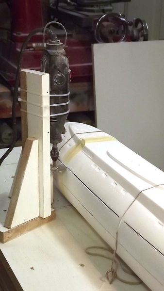
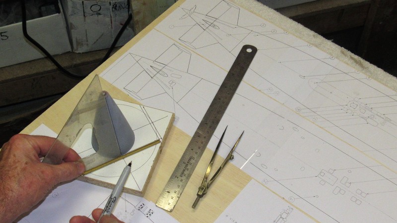
I developed a marking/assembly jig to assist me as I lay-out, mark, and attach the two stabilizer assemblies and drill the operating shaft holes for the two rudders. Symmetry is our friend!
The GRP tail-cone master -- now built up to a robust wall thickness with filler and putty, marked off as to stabilizer and rudder bore locations is test-fit to the stern of the temporarily assembled GRP hull halves to assure proper fit of the eventual tail-cone production pieces.
(As things do shrink a bit during the tool and part castings operations, I oversize the tail-cone master a bit to compensate for that unavoidable deformation).


Comment