-
quite a few sets of drawings available of the type A, but drawings are not nessissarilly correct. Especially if the person doing the drawings is not equipped with the Mark One Eyeball. There are blueprints as well but they do not depict the detail of the exterior rivets/weld seams ect. If you are referring to the ko hyoteki at the Imperial Japanese war museum on the front lawn, that particular boat was recovered from the Kehi lagoon at Pearl Harbor in 1960 and given back to the Japanese. It was damaged considerablly and was restored somewhat but lacks quite a bit of detail. The best restred example is the Ha19 in Fredricksberg Texas at the Nimitz WWII Pacific museum. Between Manfred and myself, I think we have just about every picture published of the 19 as well as several others of the Pearl Harbor boats, which were the original model type A. The other boats scattered around the world in museums and on the bottom are varrients of the sub. They appear the same to people that arnt familliar with the modifications edevelopment.Leave a comment:
-
-
That's outstandig with the rivets, I've seen several 3 dimensional wax and resin ones in various scales stuck on transfer paper. Neve had the chance to try them. Usually press my own from the back of apiece of metal with a tool. Time consuming for sure.Leave a comment:
-
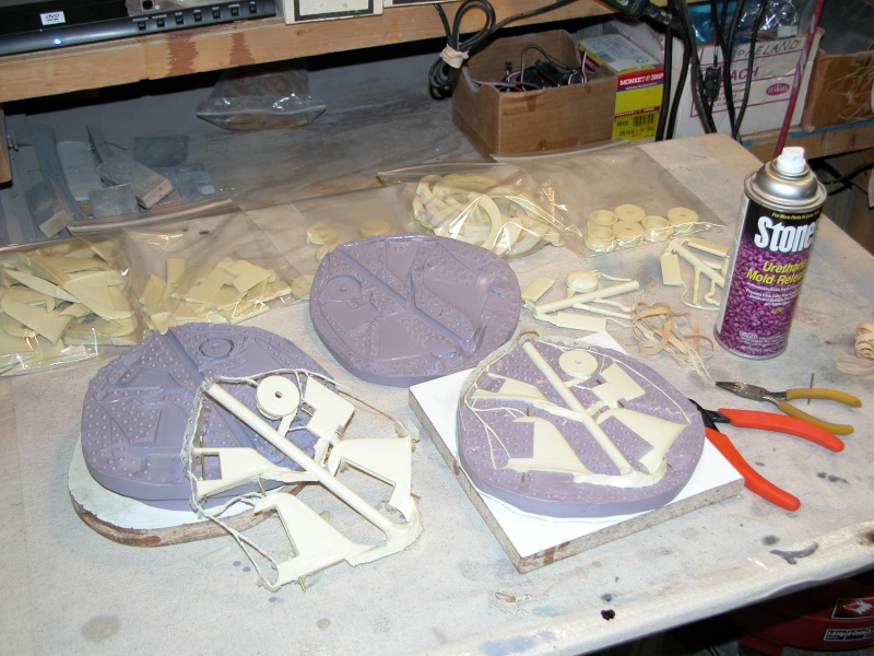
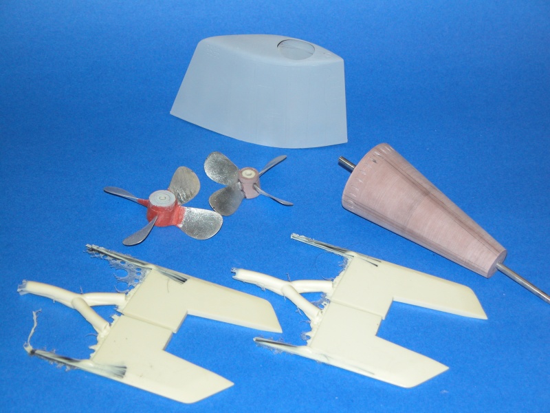
Von, that will be something for the future when the Ko Hyoteki is done, i did played with the thought of making a modular mold, so i can use different parts depending on which sub you want to build, as for the front antifauling part,
I can take mine off, the plug has to be stripped from all parts when i want to mold her.
Remember that reinforcement rod?, it's made like this, a piece of thread at the back, so by turning it round it will release the bowpart from the nut inside, so building a B type bowpart is possible and can be swapped with the A type bowpart.
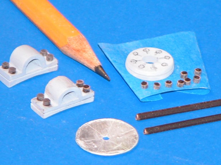
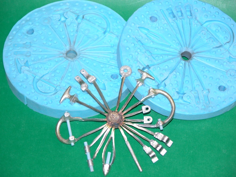
Right now she's on the bench, hollowed out the frontplate for the future tubes, resizing the pyramid part on the reinforcement rod, and started adding the rivets on the pads, bought those from a RChelicopter shop, guys at our dutch forum use them to scale up their helicopters, the head of that rivet is abour 1,5 mm, shaft about 1 mm, so i will use them also to make my tower and hull more scale, they send them in bulk, 1200 in one package, enough to build me several subs.
Manfred.Leave a comment:
-
Leave a comment:
-
-
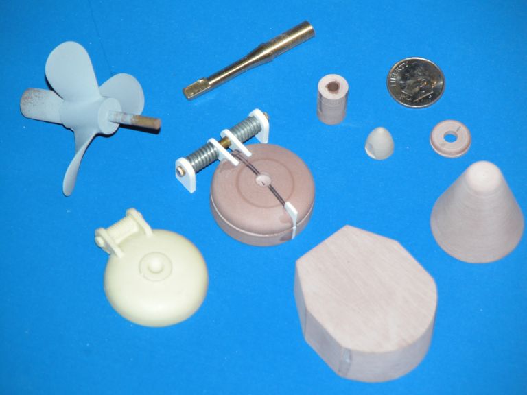
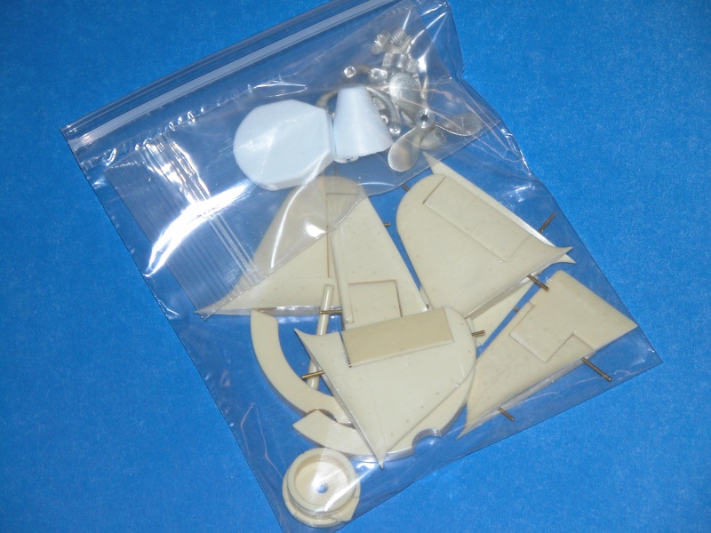
What about the kit with all the bell cranks and little parts for the rudders and planes? I could utilize one of those if you have any left.Leave a comment:
-
No, I don't believe so. I went as far as to produces an 'enhancement' fittings kit to improve the detailing of the basic William's kit -- but he stopped producing the kits (I think he assumed room temperature a while back). So, there I was: some beautiful appendages with no hull kit to go with them. Damn!
MLast edited by He Who Shall Not Be Named; 03-04-2016, 08:38 AM.Leave a comment:
-
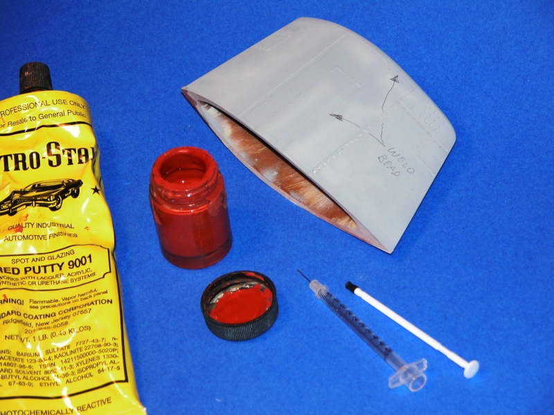
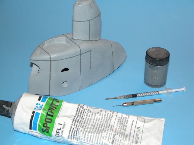
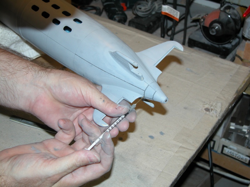
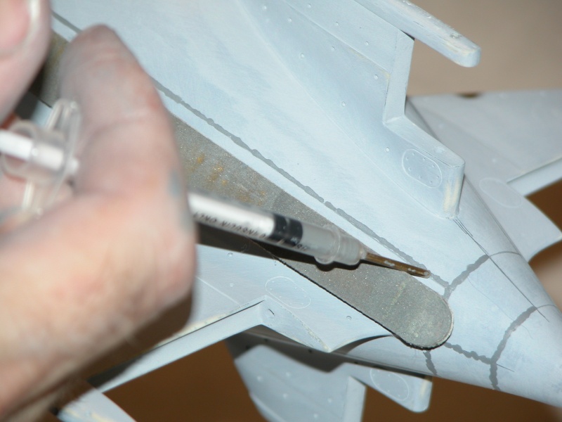
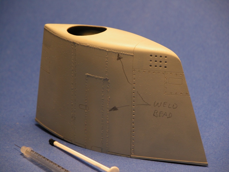
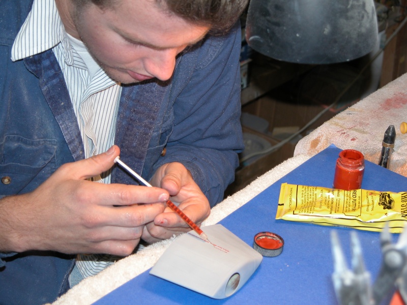
High MEK bearing lacquer thinner.
Note that I replace the way-too-small original needle with a 1/16" o.d. brass tube -- big enough to pass the putty.
If the needle clogs, it clogs at the tip, just score 1/16" back from the tip and snap off the end, exposing still wet putty. During use I ream out the needle with a drill to address any in-work clogging. The loaded putty syringe is good for about a week -- enough time to do all the work on one model -- longer than that the plunger goes sour.
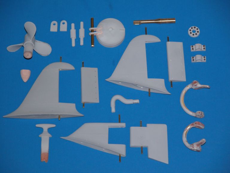
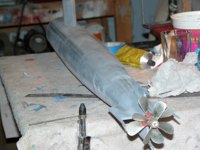
I'm showing off the 'weld lines' applied to the 1/16 Type-A master and the 1/12 KAIRYU kit.
 Last edited by He Who Shall Not Be Named; 03-03-2016, 10:26 AM.
Leave a comment:
-
What did Adam use to thin out the glazing putty? And is the hypodermic needle reusable, or hard to clean?Leave a comment:
-
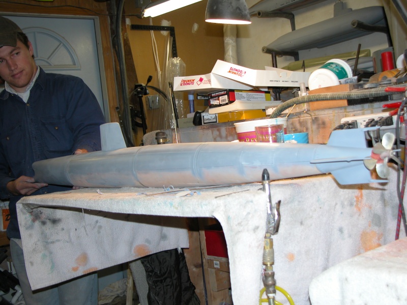
Wow, look at those counter-rotating props. What does that hull take, a 2" Subdriver? Dave , like me, youve got way too many irons in the fire at the same time. But thats what keeps this hobby interesting.Leave a comment:
-
No, his was a much smaller model.
I'm thinking of finishing this 1/16th master and working it to tooling and parts for a kit. A joint project between me and Adam many years ago. He was apprenticing here at the time -- this was his graduate project. He left it here and I secured his permission to finish it and go commercial with the thing.
Leave a comment:

Leave a comment: