-
-
-
-
Resin cast works for me. Salt water friendly. I'm going with poly on the hull this time too. 75mhz 8 ch with sombra labs gizmo means periscope operational and torpedoes are feasable as well.Leave a comment:
-
I'm delighted to see the progress, more pleased that i annoy you, so, you want to make the props light, smart move, don't forget i have to rework them to our mighty metric system, most annoying that imperial system, wouldn't be metal easier?
Why not one cast metal,and one as your new lightweight brainchild, so i can compare both.
Manfred.Last edited by MFR1964; 02-29-2016, 11:45 AM.Leave a comment:
-
Yes! Manfred's a detail-freak of the first-order! Amazing stuff. I hate his living guts!
Sure, I would be delighted to make a set of propellers for you, Dave. I got this beautiful painting of TRUTTA hanging off the wall that says so.
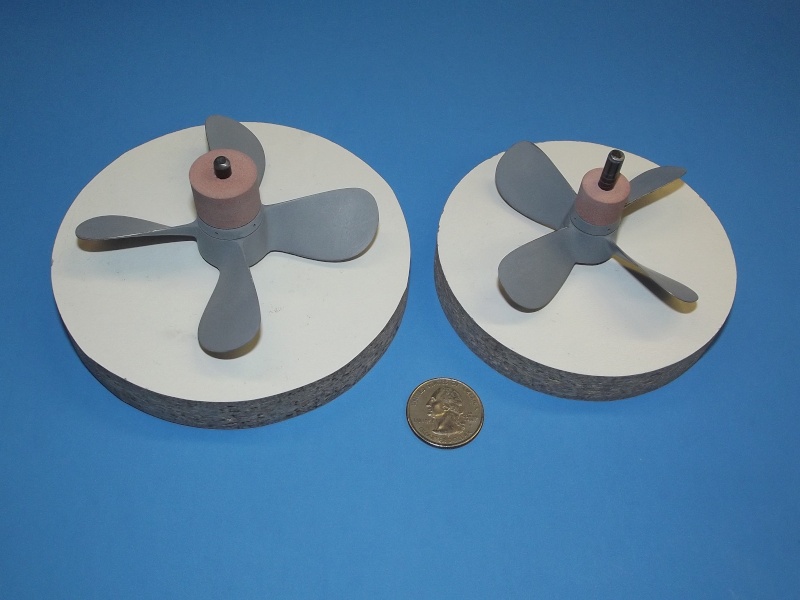
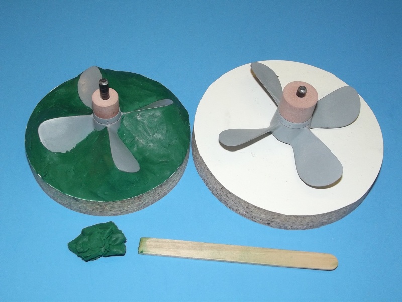
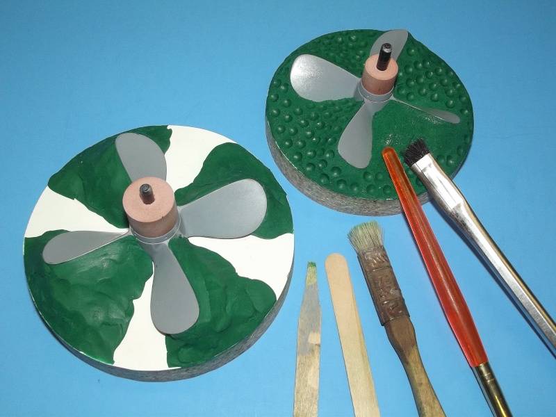
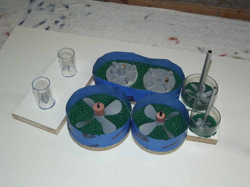
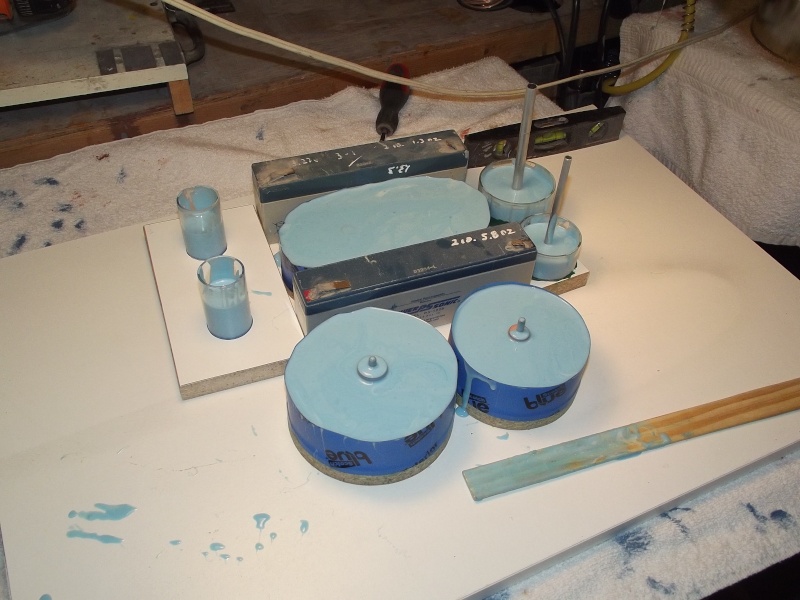
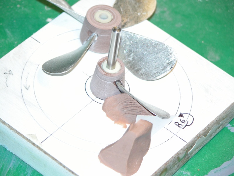
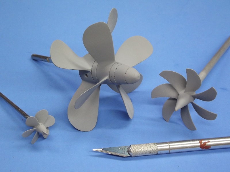
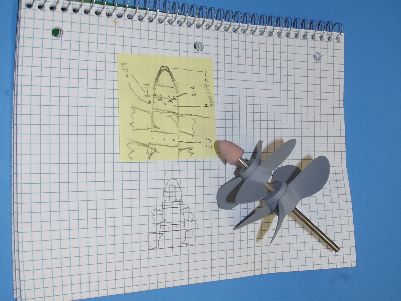
Flash-traffic for you and Manfred: I'm not going to cast these wheels from white metal as originally planned. It occurred to me that these will be too heavy to be compensated with buoyant foam aft, as the sharply tapered hull will not accommodate the foam needed. So I'm going to cast these from carbon reinforced resin. Either polyurethane or epoxy -- I'll experiment to find which is best for the task. This will entail both centrifugal and pressure casting techniques. Epoxy will give me the pot-life to do this, but takes forever to cure hard enough to de-mold. Polyurethane will make me work as fast as a NASCAR pit monkey if I'm to get the work off the spin-table and into a pot before the stuff starts to harden. We'll see. I'll vacuum cast the dunce-cap.
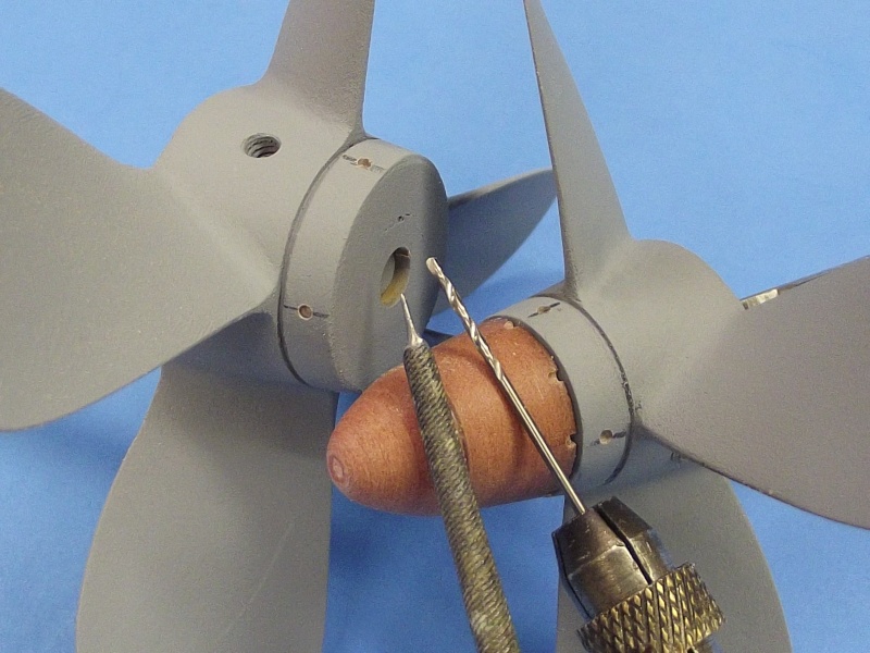
Tool making is about done -- I'm working up the second half of the tools today. Casting tonight or tomorrow. Almost done.
All this work is given me the gonads to proceed with production of the 1/16 Type-A kit. News at Eleven.
MLeave a comment:
-
once again you guys astonish me with your brilliance. Manfred, that shackle is spot on. right down to the cable crimp. Dave, when you cast up those 1/16 props, put me down for a set. I donated my 1/19 boat to the Nimitz museum. Going ahead on the 1/16th version. Tower is done, hull will be GRP this time tho. Learned alot more about the salt water issues with the type IX. Learning it the hard way is ok, my Dad said, "But you gotta be tough if your gonna be stupid" BTW thanks for the sombra labs pictures of the layout. Makes sense to me now. I have all the ducks, just didnt know the row order.Leave a comment:
-
I'm working up the masters right now for the propellers that will go on Manfred's Type-A. Should have them ready to send out by the end of the week.
Leave a comment:
-
As you guys know, the front of the Ko Hyoteki is a eyecatcher, it was a bit of a challence to get it right, mainly because of those curved metal strips that form the netcutter itself.
First i had to make this, a kind of a endcap which slides onto the nose of the foam plug kept at it's place with a threaded bar and nut, went the easy way with adding the rivets on the reinforcement ring.
Next step was to make those strips which hold the netcutter at it's place, Von warned me to keep them all straight.
By using small strips soldered to the reinforcement-ring on the inside i could solder the strips on the outside, also made those constructions at the top and bottom complete with their big rivets.
First it was time to connect the frontwire to the nose, used some home made mini shackels and locked them with bolts, there are no clear pictures present, so i went the artistic way.
Made that rod which supports the netcutter, it's too big for now, have to rework it later on, the little strip in front was used to give me a big spot to solder the netcutters.
Finally after some fiddling the front top cutter was soldered to it's place, one hurdle taken.
Playing around with the lower cutter, there is more curve on this one, so it took me a few attempts to get it right.
You tell me Von, it think i nailed her.
For now she is ready to be tinkered, i only spot soldered her, have to alter some things like that pyramid shape of the middle bar, it's way too big compared to the pictures i have.
The overal view of my progress sofar, i'm eager to get that plug ready for weldinglines , hatches and rivets, but first finish the frontpart for details.
Manfred.
Leave a comment:
-
Thanks Von,
First i'll snoop around to see what i can find, artistic license will be a good second option.
Manfred.Leave a comment:
-
Not to worry, Manfred. The only big discrepancy with the bow diflector as the boat was restored at Mare Island, is the lower part of the cage around the torpedo bore was all twisted and bent from being dragged up on Waimanlo beach across the reef for about 50 meters. When the Sandcrabs, (yard workers) in San Francisco rebuilt the front cage, they neglected to streighten the two lower horizontal brace bars. Thet are bent down slightly on the display pictures. they did a terrible job on keeping the round rings concentric as well. One other place on the display that was incorrect was the attachment point of the jumper cable. Finding a good picture of one that is correct, may be harder than finding out about the hatches. A picture of any of the boats post war may be misleading. A good picture taken by the Japanese during the war would be unlikely because it was a well guarded secret. You may have to use "artistic license"and wing it.Leave a comment:
-
The rearpart is done, only have to make the rudders and divingplanes.
Von and me had a discussion by Email about what kind of cage was placed at the Pearl Harbour Boats, to make things short, i stay with the single band cage, if there is other evidence i'll modify it to the dual band cage.
Pictures,
The ring is soldered and i added the antifauling bars both on top and on the bottom, also made a start with those bulges representing the hinges for both divingplanes and rudders.
Both horizontal stabilisers have bars at the front of the fins, mainly for the same reason as on the cage, the top fin has the antifauling cable attached, so no bar there.
The lower fin has also a bar, for now it's not attached to the hull because i only have the plug for fitting those items.
Made the attachmentpoint for the rear cable, the cable tensioner is different to the one used at the front of the conningtower, yet again had to made some shackels with bolts for securing the cable and tensioner.
This is the view towards the tower, to get the cable under tension i used elastic cord, so no worries for slack on the cable.
Now this thing is done i can put my attention to the front part, it's not that much work but i have to make certain provisions since i only have the plug, making new parts will be the main focus, and yet again roaming the net for more and better info about the construction at the bow.
There is a catch, Von warned me that the boat, Ha19, was not restored properly before it went on tour on the mainland, so i have some digging to do for more accurate pictures from before the restauration.
Manfred.
Leave a comment:

Leave a comment: