Slow down, damit!
David
-
Last few days i went ahead with the connectionsystem of the two hull parts, it's looking promising.
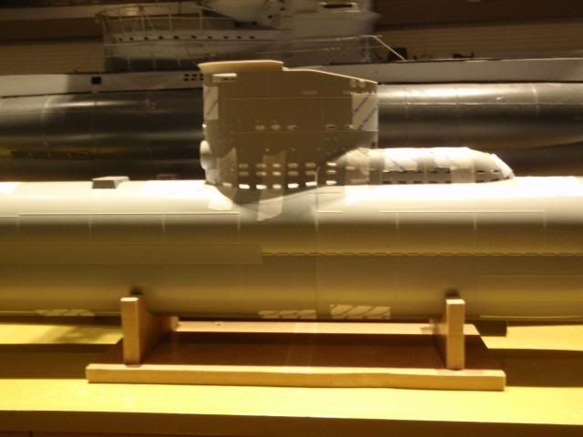
Both hullparts joined together by my system.
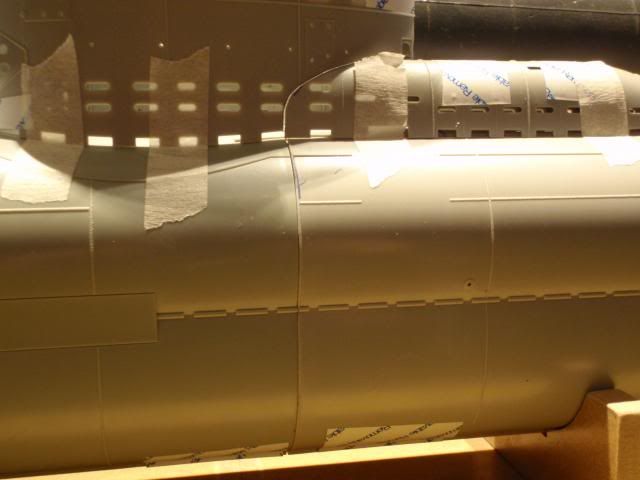
The seem is almost invisible.
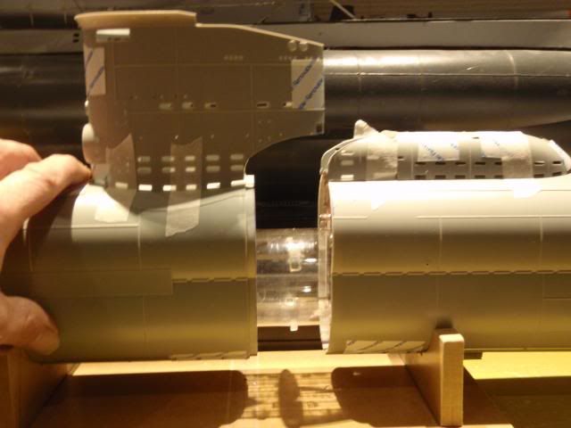
Seperating the hull, i used a jewellersaw to get the exhaustcover splitted from the conningtower.
You can slide the SD out of the hullparts, for now i have to build it up in such way that i can use it for my way of splitting the hull.
Manfred.Leave a comment:
-
David,
Don't worry about that, it happens in the heat of the battle, that's called passion for the hobby.
Manfred.Leave a comment:
-
My apology, Manfred.
I just realized you started this thread. I lost track of that and posted my stuff here. Just letting you know I caught that and will post my work on this fine kit in another thread. Sorry about that pal ... I hate it when people step on my toes, and I want to assure you this was an over-sight on my part, not an intentional interruption of your good work.
DavidLeave a comment:
-
-
Oh, oh .... Manfred's on the March! I better get to it.Leave a comment:
-
The entire cage would have to contain the entire snorkel mechanism to be effective. I have not, and have yet to get a fouled snorkel inlet due to crap in the water.
DavidLast edited by Outrider; 03-22-2013, 09:39 PM.Leave a comment:
-
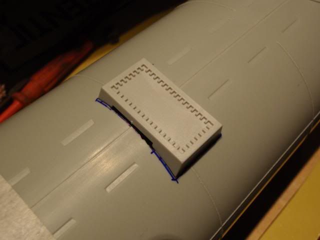
This is the battery hatch of the type XXIII, since i use the vertical split, i had a other use for this hatch.
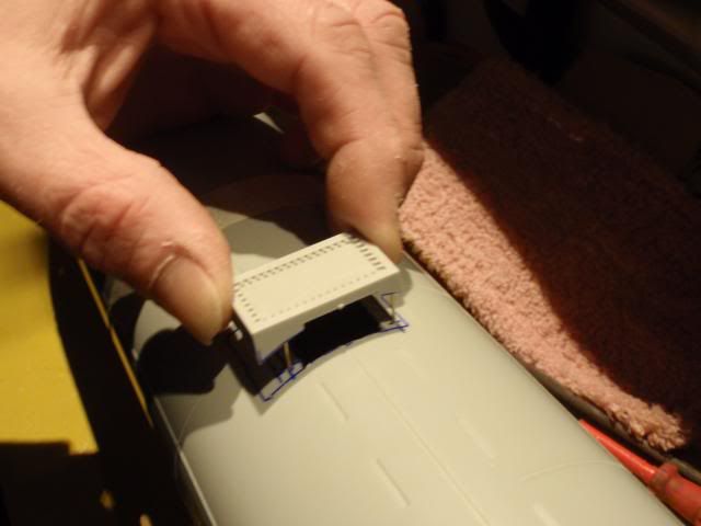
You can lift it up, this is the first fase of opening the hatch.
One side has static pins, the other side a hidden hinge, so you can swiffle the hatch open far enough for free access.
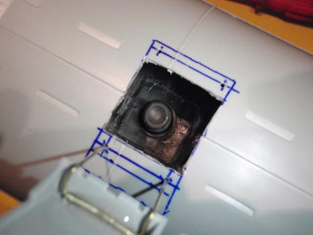
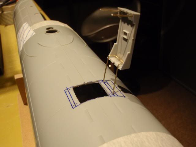
Allready adapted the SD with the power switch on top, which i can reach with a finger through the opening, one arrow dodged.
Manfred.Leave a comment:
-
David,
How tough would it be to create a plastic mesh cage to filter particles, if that is a concern?Leave a comment:
-
No, Sam. It's a solid resin block that has been ported to direct air from the inlet nipple, through the block channel, and into the top of the brass snorkel induction tube.
I've been operating the SAS type system, and all variants employ the same type induction valve, and have yet to pick up crap big enough to cause a flooded induction line .... famous last words!Leave a comment:
-
-
Got the attachment gizmo between sail and hull worked out. 3/16" diameter resin rod (sprue from casting work) was bored out and tapped to take 4-40 studs. One was glued at the forward end of the sail, the other was glued at the after end of the engine exhaust muffler fairing -- these became the foundations through which studs were attached and used to jack the sail down tight upon the upper hull.
After working out the location of the snorkel assembly I removed as much deck under the sail as possible -- the object of the game is to minimize the volume of structure above the waterline; less displacement above, means less ballast tank needed below.
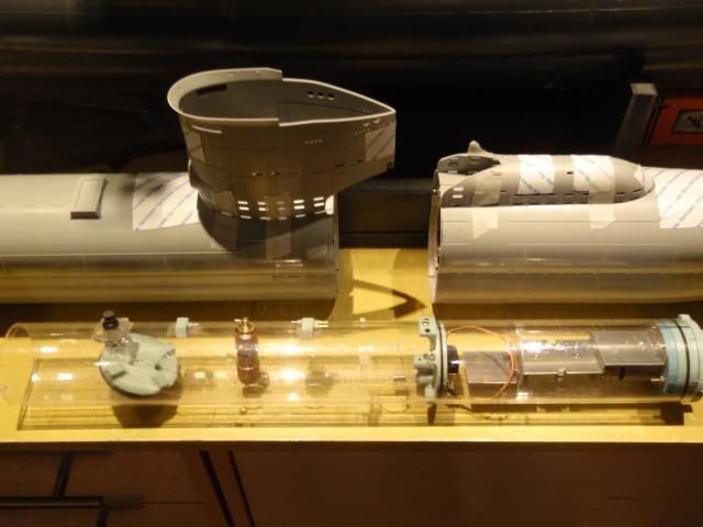
Did some more work on the fittings kit masters, and laid out what I've done to date out for your inspection.
Important to build up a lapping plate on the inside upper hull longitudinal seam, or the left and right sections of that part will split on you. Some filler rod in the narrow gap at the stern -- stretched sprue off a bit of the kits parts tree. After all that dried, I put Ellie to work, evening out the edges where the upper hull meets the lower hull.
And worked out the snorkel unique to this particular boat.
Leave a comment:
-
Thanks for the reminder -- the completed, unpainted cast white-metal (Tin-Antimony) propeller will be machined smooth, dunked in vinegar a few minutes, then will be given a flat clear coat to stop oxidation. Good call on that!
... and some shots of master work in support of the eventual fittings kit.
David
Last edited by He Who Shall Not Be Named; 03-18-2013, 04:03 PM.Leave a comment:
-
Actually, as the 1/32 and 1/35 weapon will employ the identical breech-block mechanism used on the 1/72 weapon, what I will be doing is grafting on that type brass assembly to the existing kit provided torpedo tube.
A tight fit between torpedo body and tube is not important. Make-up of the weapons nozzle tube to the breech-block O-ring and positive engagement of the stop-bolt to the warhead of the weapon is.
Leave a comment:

Leave a comment: