
 Tweet
Tweet
Thanks David, will be referencing this post for Handrails
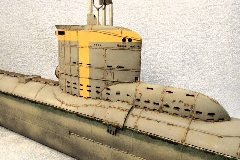
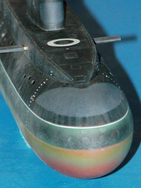
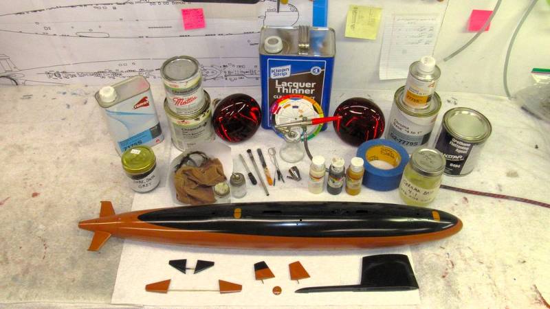
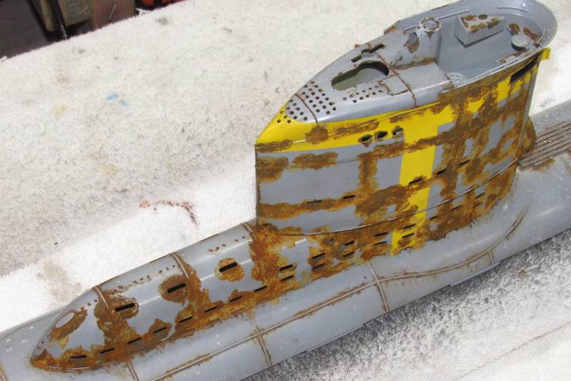
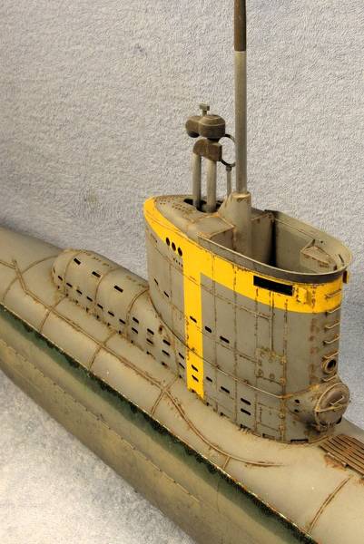
The kit supplied plastic railing that girdle the sides of the sail are just too fragile to be serviceable on a practical r/c submarine. So, I substituted brass wire railings.
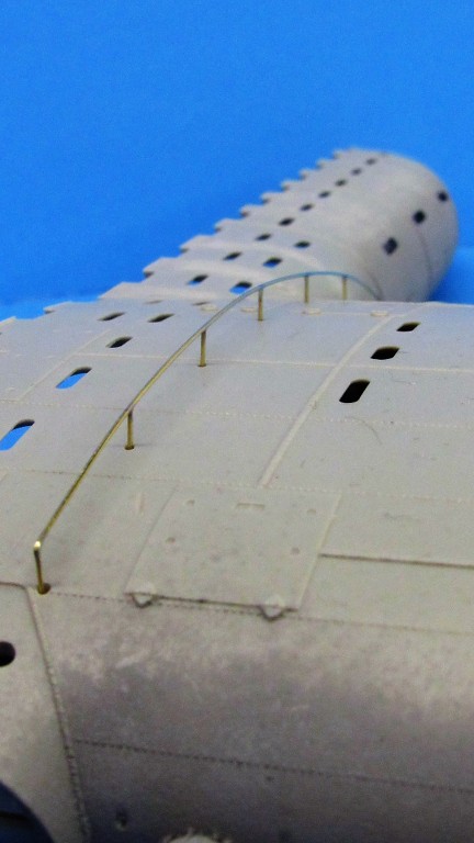
The two brass railing assemblies are formed of .020-inch diameter brass rod. The pins are about .375-inch long, pointed at the inboard end, and ground to a flat at the outboard end.
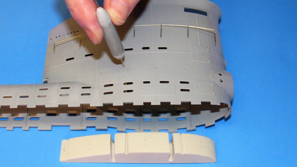
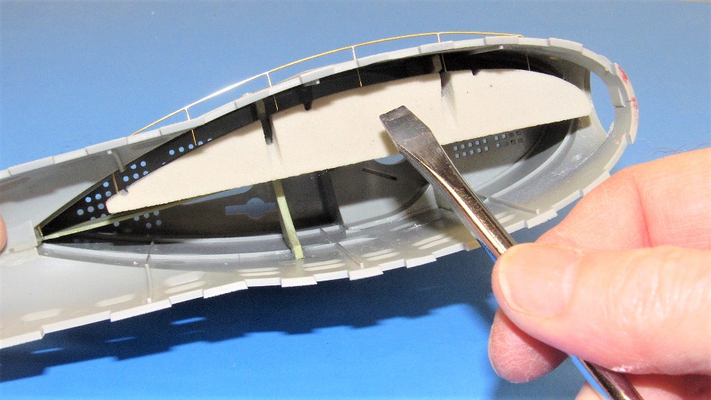
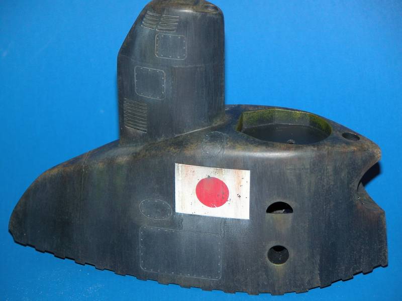
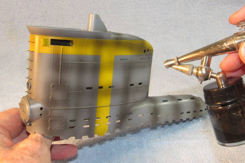
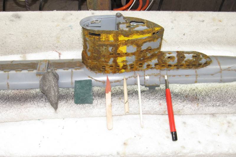
The RenShape pin-retainer, which temporarily resides within the sail -- and conforms to the curve there -- securely holds the embedded pins in place and also serves as a heat-sink to rapidly dissipate soldering heat away before the easily melted polystyrene plastic of the sail.
After the pin-retainer is installed within the sail (shown outside so you can see how it would be used) the bore clearing-pin setting tool is used to push a pin through one of the .023-inch holes that have been drilled through the side of the sail.
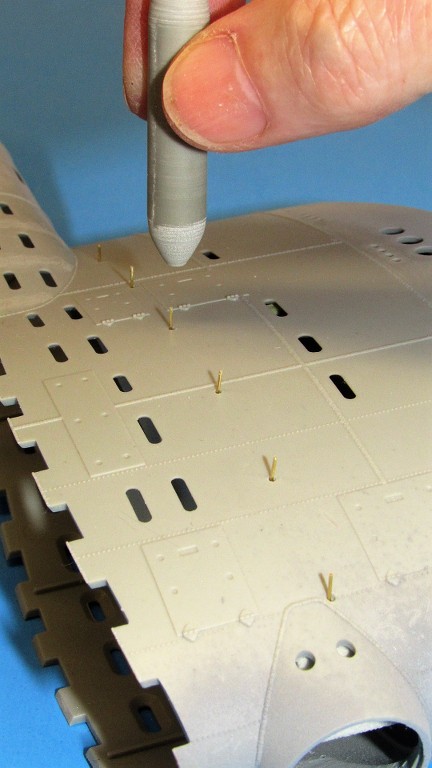
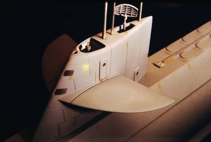
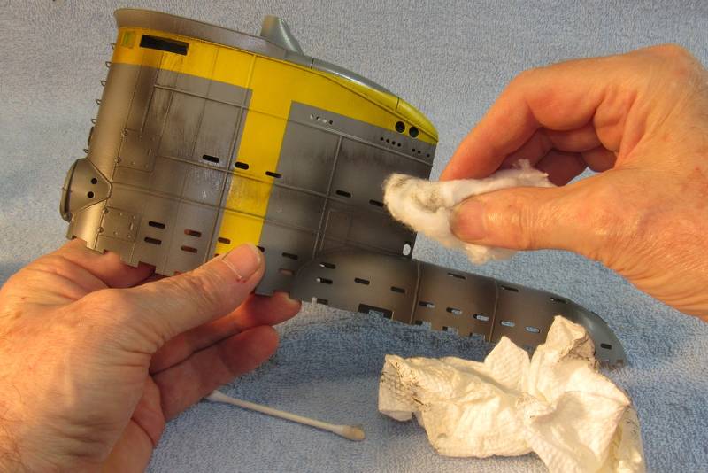
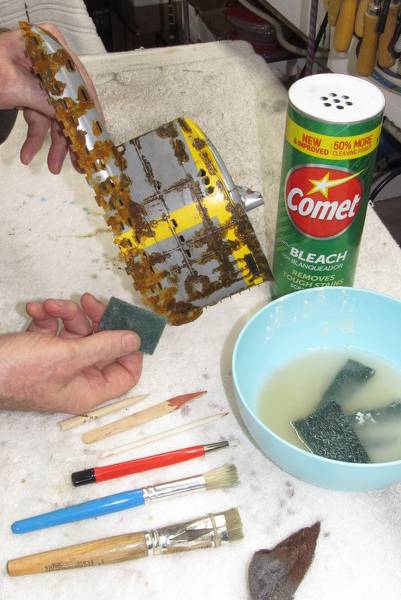
Pulling the bore clearing-pin setting tool away from the work leaves the pin well embedded into the pin-retainer bearing against the inside of the sail. Use of the tool results in an array of railing pins projecting from the side of the sail, all of the same height.
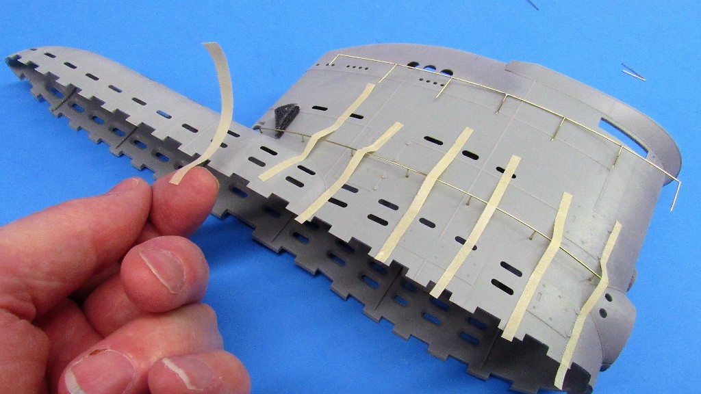
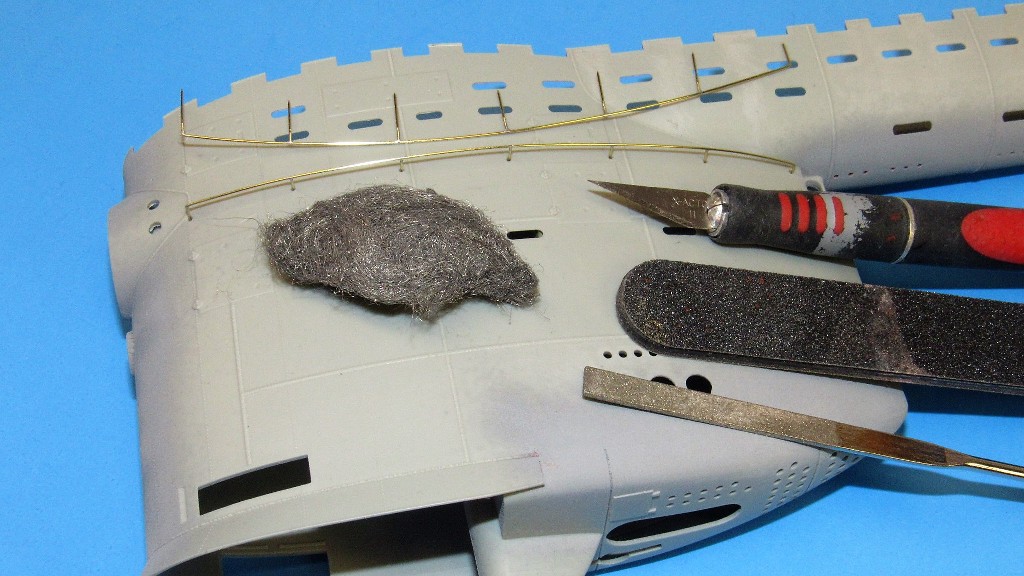
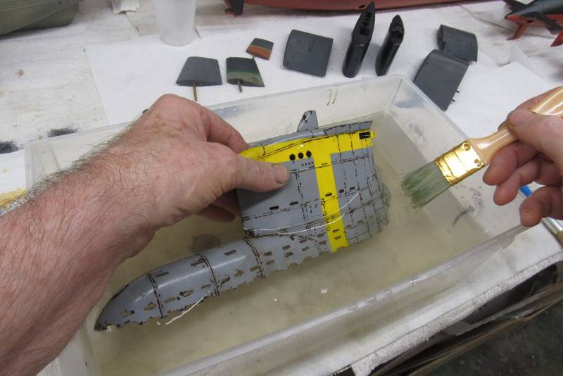
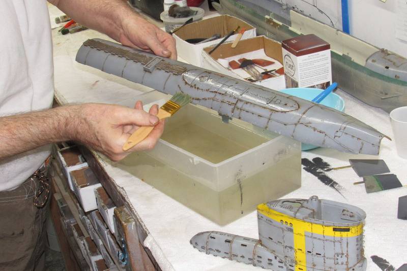
A long length of brass rod becomes the railing proper. Here I'm using thin strips of masking tape to secure the railing over its pins. Note the finished railing assembly laying near the top of the sail. With the aid of the internal pin retainer the sail itself becomes the holding fixture of the parts that, once soldered together, become a railing assembly.
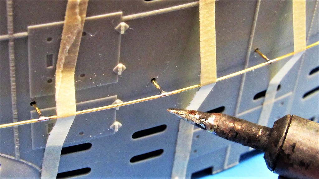
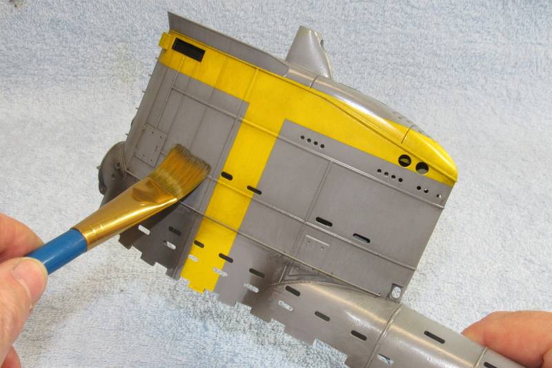
The secret to keeping the heat localized to the joint is a hot soldering iron tip; a tip that is ground small to minimize heat transfer to non-joint structures; and use of the pin-retainer which also acts as a heat-sink.
The tip of the iron is applied to the joint with half-second jabs, just long enough to get good solder flow, as evidenced by these small, tight fillets between rail and pin.
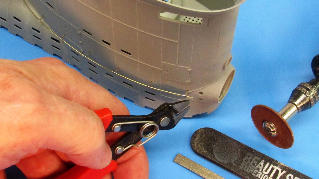
Snipping off the excess railing at the forward-most pin. The raw end here would be worked with file and sanding stick after contouring with very light, carefully applied jabs of the carbide cut-off wheel.
While still in place on the sail the railing assembly has all the solder unions cleaned up by scraping away excessive fillet with a blade; sanding and filing away solder and crystallized flux; and finally abrading away all scratch-marks with a good polishing using #0000 steel-wool.
After all soldering and clean-up work had been done on the railing assembly the RenShape pin-retainer, within the sail, was pried away from the pins and removed.
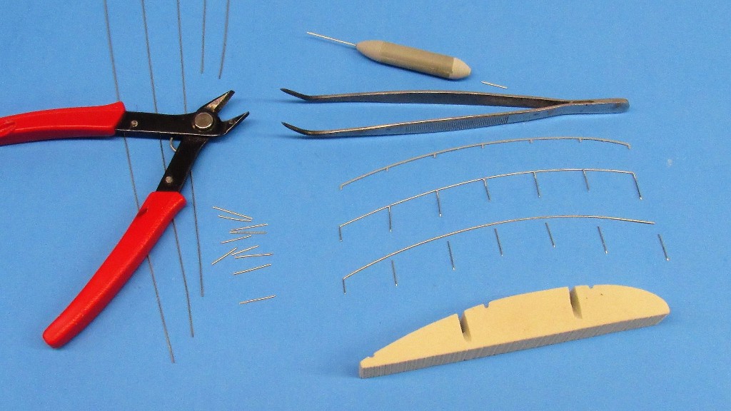
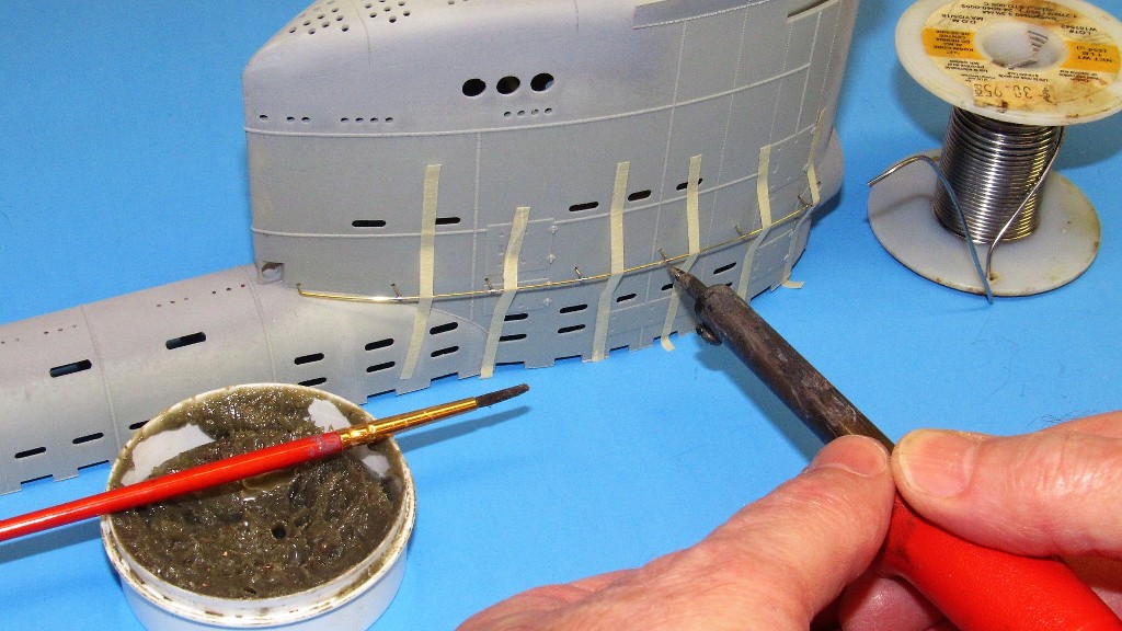
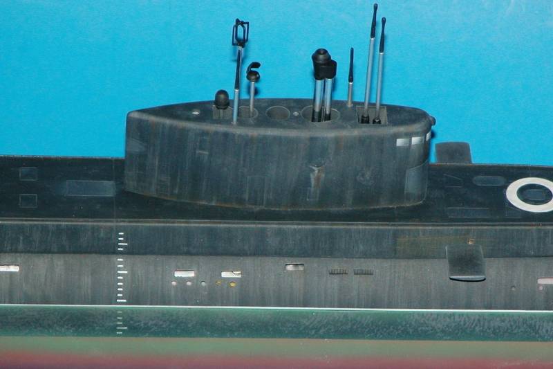
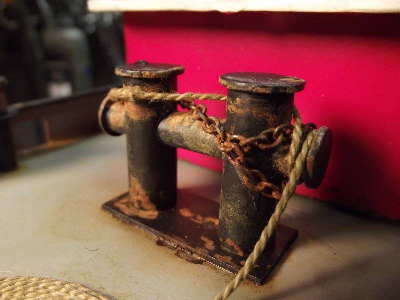
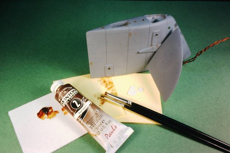
The pin-retainer is used as a handling fixture if any further work on a railing is required off-sail. Note the three items needed to do the soldering: a 35-Watt soldering iron with custom ground tip; acid paste flux; and 60/40 solder. At the bottom of this shot is the bore clearing-pin setting tool.

The kit supplied plastic railing that girdle the sides of the sail are just too fragile to be serviceable on a practical r/c submarine. So, I substituted brass wire railings.
The two brass railing assemblies are formed of .020-inch diameter brass rod. The pins are about .375-inch long, pointed at the inboard end, and ground to a flat at the outboard end.
The RenShape pin-retainer, which temporarily resides within the sail -- and conforms to the curve there -- securely holds the embedded pins in place and also serves as a heat-sink to rapidly dissipate soldering heat away before the easily melted polystyrene plastic of the sail.
After the pin-retainer is installed within the sail (shown outside so you can see how it would be used) the bore clearing-pin setting tool is used to push a pin through one of the .023-inch holes that have been drilled through the side of the sail.
Pulling the bore clearing-pin setting tool away from the work leaves the pin well embedded into the pin-retainer bearing against the inside of the sail. Use of the tool results in an array of railing pins projecting from the side of the sail, all of the same height.
A long length of brass rod becomes the railing proper. Here I'm using thin strips of masking tape to secure the railing over its pins. Note the finished railing assembly laying near the top of the sail. With the aid of the internal pin retainer the sail itself becomes the holding fixture of the parts that, once soldered together, become a railing assembly.
The secret to keeping the heat localized to the joint is a hot soldering iron tip; a tip that is ground small to minimize heat transfer to non-joint structures; and use of the pin-retainer which also acts as a heat-sink.
The tip of the iron is applied to the joint with half-second jabs, just long enough to get good solder flow, as evidenced by these small, tight fillets between rail and pin.
Snipping off the excess railing at the forward-most pin. The raw end here would be worked with file and sanding stick after contouring with very light, carefully applied jabs of the carbide cut-off wheel.
While still in place on the sail the railing assembly has all the solder unions cleaned up by scraping away excessive fillet with a blade; sanding and filing away solder and crystallized flux; and finally abrading away all scratch-marks with a good polishing using #0000 steel-wool.
After all soldering and clean-up work had been done on the railing assembly the RenShape pin-retainer, within the sail, was pried away from the pins and removed.
The pin-retainer is used as a handling fixture if any further work on a railing is required off-sail. Note the three items needed to do the soldering: a 35-Watt soldering iron with custom ground tip; acid paste flux; and 60/40 solder. At the bottom of this shot is the bore clearing-pin setting tool.


 [/URL]


Comment