-
Probably similar, but with NAVSEA procurement, you never know.
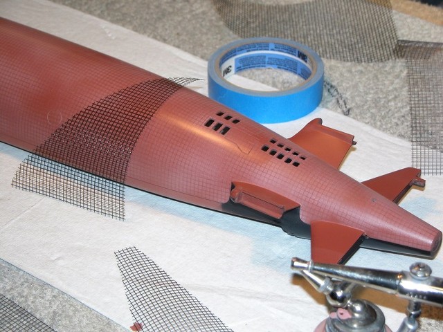
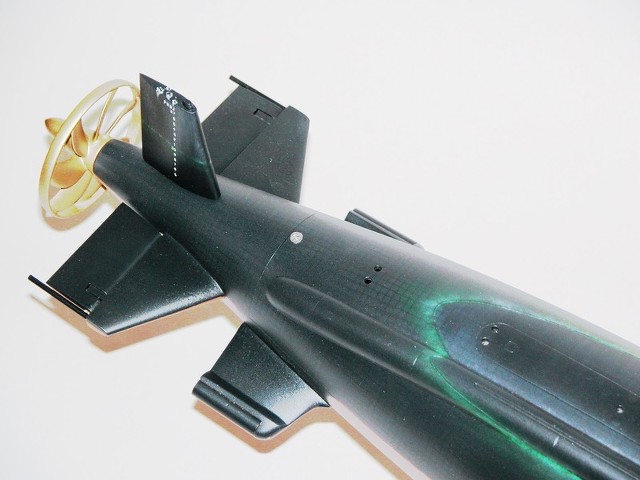
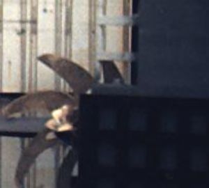
These photos of the OK-276 Towed Array Handling System, (two systems per Trident, one for fast boats) show the major components. The Thinline T/A uses a dual sheave drive unit as part of the OK-542 handling system. The thinline array is longer than than the TB-16 Fatline array
I went to school for both (NSWC Crane, IN) and many components are shared.
The Control Indicator operates the deployment and retraction cycles. It is located within sight of the Storage Drum --since that's the most likely component to tear off limbs.
The Cable Drive Unit supplies the force to move the tow cable in either direction.
The Storage Drum stows the tow cable. An attached Level Wind Unit ensures the cable wraps are uniform and don't overlap until they reach the edges of the drum. For loading, we would wrap slow and use a 2 x 4 to position the cable manually for extra-tight wraps.
The valve stack is positioned directly above the CDU and provides a seal for the tow cable to exit the pressure hull.
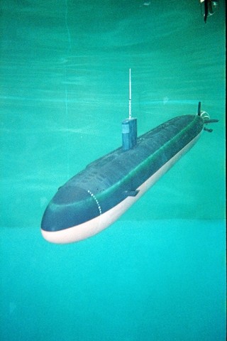
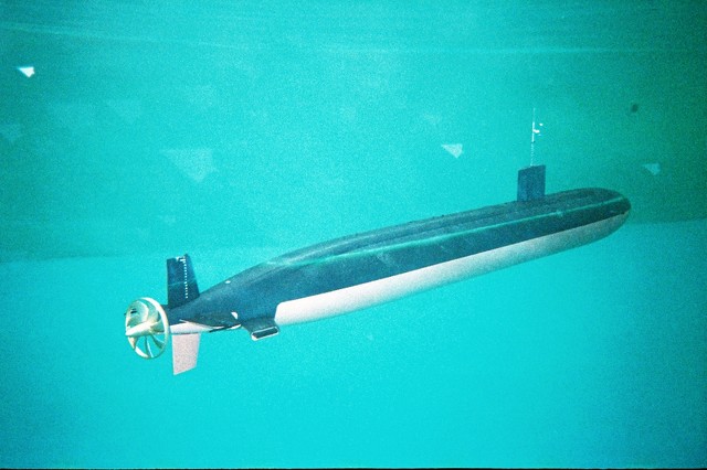
For comparison, the BRA-24A system:
Attached FilesLeave a comment:
-
-
I'm thinking that the valve stack is/was very similar to that on the BRA-24 Floating Wire antenna mechanism. Intimately familiar with that one from my time at NSSF, NLON! I have many stories regarding that little ball, both in-shop and aboard ship. Not all of them fun!!!!Leave a comment:
-
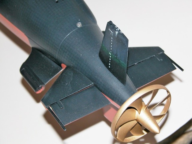
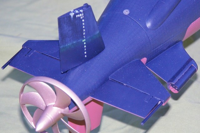
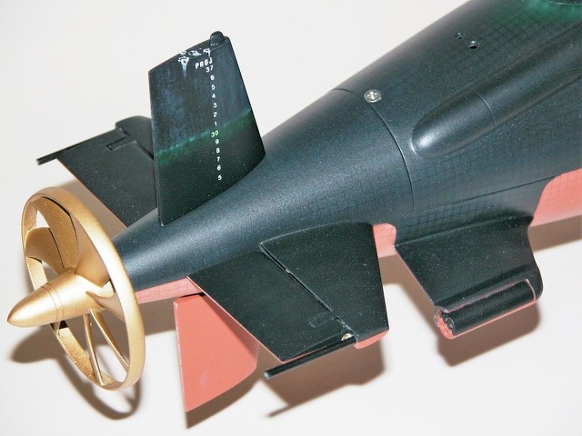
The array tow points are designed to keep the array and tow cable, (3/8" diameter) away from the screw under normal operation. Screws are a lot more expensive than arrays and their replacement can keep a boat sidelined for an extended period.
When streamed full scope, the array's tow cable is under a tremdous amount of tension. The easiest way to destroy a tow cable is going from a flank to a backing bell when streamed. The tow cable develops kinks that cannot pass through the hull penetrator on its way to the inboard storage drum just below it, forcing the crew to shear the cable. How does the hole through the pressure hull seal then? The conical entrance in the valve stack uses a 1/2" steel ball that falls into the hole and seals it using outside pressure to keep it centered. Not saying it doesn't drip, but it's better than a through-hole.
A fast boat, (USS Olympia, I think) came into Bangor with a constantly leaking tow cable seal. The sonarmen said it had always leaked. Being a SUBSAFE job, I carried a phone-book sized work package back and forth between the various shops for signatures and QA verification when I wasn't on the boat working the job. The valve stack (about 24" high) went to the valve shop for seal replacement and was re-installed aboard the boat and the old tow cable reloaded.
The boat returned from sea trials and the CO was ****ed. The seal leaked considerably more than before we worked on it. We off-loaded the cable, and removed the valve stack once more. A more detailed inspection revealed the valve stack was not built to the drawing spec (a machined section was out of tolerance) at Norfolk Naval Shipyard seven years before. Being a SUBSAFE job, this was reported immediately. We remachined the section, reinstalled everything and the seal was properly repaired.
The guy who signed the SUBSAFE paperwork off for the valve seven years earlier was not so fortunate- he was fired as soon as they found out he was still working there. I didn't see many people get fired over the years I spent there, but those that were usually had deviated from SUBSAFE requirements. Talk about a work package nightmare!
Lesson Learned: There is no Statute of Limitations for SUBSAFE work.âLast edited by CC Clarke; 02-21-2023, 11:12 AM.Leave a comment:
-
Another possible reason I could think of is to avoid tnterferece of the porpeller blades with the towed sonar array.Leave a comment:
-
-
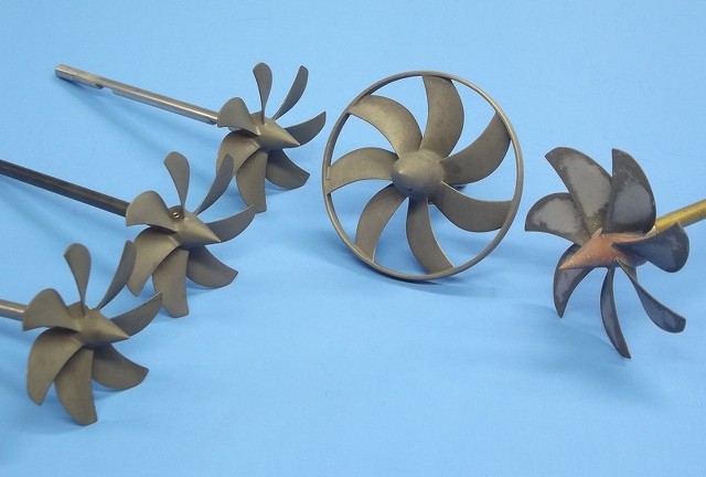
Whats's the ring around the propeller good for? Reduction of vortices? Minimizing vibrations?Leave a comment:
-

Back when Ellie and I were building defense contractor convention model displays we got the job of building three of these things (fairing and canaster) for an outfit I should not mention -- seems the salespeople gave us classified drawings to work from and the Navy went ballistic when they saw the model display at the big Navy League show in DC. We kept our heads down for a good long while after that ****storm. D&E Miniatures never sought or secured a DoD classification ranking, and our customer failed to check that box when they took us on, a third-party, for the display.
DavidLast edited by He Who Shall Not Be Named; 02-20-2023, 04:32 PM.Leave a comment:
-
I need some help on the countermeasures. These drawings are what I have but trying to shape the front view of the pod is confusing. The after end works well so far but it needs more work.
I searched for pictures of LA class subs on drydock and found these below.
The first is USS Topeka cropped and edited to get a better look at the pod. The other two photos are similar but I can't recall the names.
Each photo makes it look like the forward end of the pod looks similar to the after end of the pod.
Can someone with first-hand experience point me in the right direction?
Will Rogers
SSBN659Attached FilesLeave a comment:
-
-
As I looked back at posts 45. 46 & 57 and CC Clarke's description of the Active Emissions intercept Hydrophones (hope I got the right) convinced me to add that to the model. Working at a scale of 1/113 is a challenge so the hydrophone on the model is just over 1/4 inch high.
While researching for my model I found this gem and am now working on the tubes for the fat-line and thin-line arrays.
The countermeasures are also in the works.
Will Rogers
SSBN659
Leave a comment:
-
Lovely! Same, though in smaller scale, is next on the list of my beluga build. That LA will be an eye- catcher!
J�rgLeave a comment:
-
I got one of Will's VICTOR-3 GRP hulls and it's a beaut!
DavidLeave a comment:
-
Hi Jorg thanks for your comments. This will be a display model only not a master for a rubber mold and fiberglass layup. Several years ago I did a Victor III and a Kilo in fiberglass and posted them here but no plans to do one now.
Will Rogers
SSBN659Leave a comment:


Leave a comment: