A Skipjack in Ireland

Collapse
X
 
  • Time
  • Show
Clear All
new posts
  • The Boattrainman
    Commander
    • Mar 2016
    • 443

    #181
    Seriously pi**ed off with Hobbyking, no sign of my order, so gone elsewhere for servos etc!!!

    In the meantime, I need access to the hull for some sort of On/Off switch, there's a hatch on the forward deck which gets opened up.


    Click image for larger version  Name:	IMG_0828 (800x600).jpg Views:	1 Size:	237.7 KB ID:	119574Click image for larger version  Name:	IMG_0829 (800x600).jpg Views:	1 Size:	212.3 KB ID:	119575


    This fitting is made to go under the hatch from 1mm styrene.

    Click image for larger version  Name:	IMG_0830 (800x600).jpg Views:	1 Size:	237.6 KB ID:	119576Click image for larger version  Name:	IMG_0831 (800x600).jpg Views:	1 Size:	235.0 KB ID:	119577


    The fitting gets sides and a new hatch is made with lugs to take a 1.5mm brass hinge.

    Click image for larger version  Name:	IMG_0832 (800x600).jpg Views:	1 Size:	226.2 KB ID:	119578Click image for larger version  Name:	IMG_0834 (800x600).jpg Views:	1 Size:	212.2 KB ID:	119580


    The hatch opens and closes and is a pressure fit in the hole, which is big enough to poke a screw driver or small rod into.

    Click image for larger version  Name:	IMG_0833 (800x600).jpg Views:	1 Size:	220.3 KB ID:	119579


    I'll figure out what the access is to later, but it means I can turn some sort of main switch on without opening the hull.

    The Boattrainman
    Last edited by The Boattrainman; 02-06-2017, 05:59 PM.
    ''We're after men, and I wish to God I was with them........!''

    Comment

    • Greevesman
      Ensign
      • Dec 2016
      • 48

      #182
      Nautilus Drydocks has a remote radio controlled on off switch. No need for a hole.

      Comment

      • The Boattrainman
        Commander
        • Mar 2016
        • 443

        #183
        Hi Greevesman,

        With you 100,%, saw Bob's products, the electronic starter is a great idea.

        BUT

        As I mentioned earlier, the cost of postage and tax from the USA will put the product at around 60 plus Euro, which I can't justify for this build given the Sub kit itself cost 65 Euro. Also, I prefer mechanical On/Off switches as the boat is complete, you don't need any additional items other than the TX to operate. Here's the set up disguised on my last build.


        Click image for larger version  Name:	IMG_0835 (800x600).jpg Views:	1 Size:	286.1 KB ID:	119586Click image for larger version  Name:	IMG_0836 (800x600).jpg Views:	1 Size:	287.4 KB ID:	119587


        I prefer to think of the Sub as coming with a working forward hatch!

        Rob

        Last edited by The Boattrainman; 02-07-2017, 06:58 AM.
        ''We're after men, and I wish to God I was with them........!''

        Comment

        • Albion
          Captain
          • Dec 2008
          • 651

          #184
          i cut out the round hatch just aft of the hole you, no where near big enough :(, might revisit that decision looking at your work
          Next time someone points out it takes 42 muscles to frown, point out it will only take 4 muscles to b1tch slap them if they tell you how mnay muscles you need to smile:pop

          Comment

          • The Boattrainman
            Commander
            • Mar 2016
            • 443

            #185
            Hi Albion,

            I did consider that round hatch, but I had put the Photo-etched part there and didn't want to spoil that work.

            It doesn't look very prototypical when opened, I was actually surprised at the thickness of the plastic here (around 2.5mm), the access hatch looks like it's made of six inch thick steel!!!

            Rob
            ''We're after men, and I wish to God I was with them........!''

            Comment

            • The Boattrainman
              Commander
              • Mar 2016
              • 443

              #186
              The hatch mechanism is held in place by a slot and tab mechanism and a small screw (sorry that second photo isn't great).

              I'd rather glue it in place but as Murphy's Law (another Irishman by the way!) has it, any part that you can't service will be the first to fail.


              Click image for larger version  Name:	IMG_0837 (800x600).jpg Views:	1 Size:	240.7 KB ID:	119596Click image for larger version  Name:	IMG_0838 (800x600).jpg Views:	1 Size:	191.5 KB ID:	119597


              The hatch sits flush to the hull and by having the hinge at the 3/4 point it opens by pushing down on one end.

              Click image for larger version  Name:	IMG_0839 (800x600).jpg Views:	1 Size:	212.0 KB ID:	119598Click image for larger version  Name:	IMG_0840 (800x600).jpg Views:	1 Size:	216.9 KB ID:	119599


              The Boattrainman
              Last edited by The Boattrainman; 02-07-2017, 05:12 PM.
              ''We're after men, and I wish to God I was with them........!''

              Comment

              • The Boattrainman
                Commander
                • Mar 2016
                • 443

                #187
                The servos are positioned in holes cut in the aft of the tech rack, two over and one under.

                Click image for larger version

Name:	IMG_0841 (800x600).jpg
Views:	561
Size:	238.5 KB
ID:	119610Click image for larger version

Name:	IMG_0842 (800x600).jpg
Views:	284
Size:	236.8 KB
ID:	119611


                It's going to be a busy end cap here, with three servo arms, the piston tank inlet/outlet, a12v connection for lights and the prop shaft.

                The Boattrainman


                ''We're after men, and I wish to God I was with them........!''

                Comment

                • The Boattrainman
                  Commander
                  • Mar 2016
                  • 443

                  #188
                  Holes are drilled to take 6mm brass tubes and the wires for the lights (2 for the rear light and 2 for the lights in the sail).

                  Click image for larger version

Name:	IMG_0843 (800x600).jpg
Views:	259
Size:	233.9 KB
ID:	119650


                  The styrene surrounds are filled with epoxy, nothing new here.

                  This is not really all that enjoyable, having worked hard to get an airtight WTC, drilling the end cap full of holes is bad for the nerves!


                  Click image for larger version

Name:	IMG_0845 (800x600).jpg
Views:	257
Size:	215.5 KB
ID:	119651


                  The Boattrainman
                  ''We're after men, and I wish to God I was with them........!''

                  Comment

                  • trout
                    Admiral

                    • Jul 2011
                    • 3658

                    #189
                    Suggestion, for next time, the 4 wires that you drilled holes for. Put in 4 rods or solid brass wire, then solder the wires to that. David once shared that water worked its way through the sheathing and allowed water to get in. By soldering to the wire you make a dam that stops that, then you can seal it all in.
                    If you can cut, drill, saw, hit things and swear a lot, you're well on the way to building a working model sub.

                    Comment

                    • The Boattrainman
                      Commander
                      • Mar 2016
                      • 443

                      #190
                      Hi Trout,

                      Great tip, I'm stuck with the direct wires through the hull method on this one!

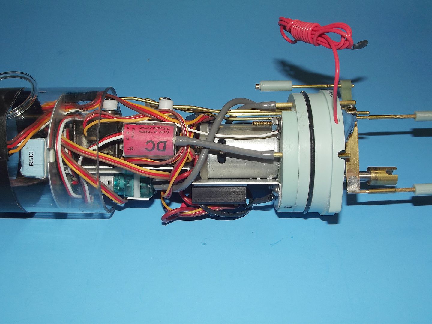
                      This is what the back of WTC now looks like.


                      Click image for larger version  Name:	IMG_0847 (800x600).jpg Views:	1 Size:	261.4 KB ID:	119691Click image for larger version  Name:	IMG_0848 (800x600).jpg Views:	1 Size:	279.5 KB ID:	119692


                      The push rods are all in line, bent to the same angle and joined with brass collars that have been drilled to be a tight fit on both rods.

                      Click image for larger version  Name:	IMG_0850 (800x600).jpg Views:	1 Size:	282.0 KB ID:	119693Click image for larger version  Name:	IMG_0849 (800x600).jpg Views:	1 Size:	281.0 KB ID:	119694


                      The lower servo joins the reverse throw fitting, the servo arm of which has now been cut down to size and will take the movement up to the sail planes. It's all plastic, brass or stainless steel in the flooded areas.

                      Click image for larger version  Name:	IMG_0851 (800x600).jpg Views:	1 Size:	246.2 KB ID:	119695


                      The Boattrainman
                      Last edited by The Boattrainman; 02-10-2017, 04:22 PM.
                      ''We're after men, and I wish to God I was with them........!''

                      Comment

                      • The Boattrainman
                        Commander
                        • Mar 2016
                        • 443

                        #191
                        Here is what the forward end of the WTC now looks like.

                        Click image for larger version  Name:	IMG_0852 (800x600).jpg Views:	1 Size:	227.1 KB ID:	119697Click image for larger version  Name:	IMG_0853 (800x600).jpg Views:	1 Size:	247.5 KB ID:	119698


                        The main switch push rod exits the WTC and send in two brass collars. The switch is loose till I decide it's exact location.

                        Click image for larger version  Name:	IMG_0855 (800x600).jpg Views:	1 Size:	234.4 KB ID:	119699Click image for larger version  Name:	IMG_0856 (800x600).jpg Views:	1 Size:	215.6 KB ID:	119700


                        The two collars finish up under the opening hatch and between the lugs of the hatch mounting mechanism under the fore deck when both halves of the hull are attached.

                        Just stick a small screw driver head or other rod in the gap between the collars and turn the boat On or Off. Simple.

                        The Boattrainman


                        Last edited by The Boattrainman; 02-10-2017, 05:11 PM.
                        ''We're after men, and I wish to God I was with them........!''

                        Comment

                        • The Boattrainman
                          Commander
                          • Mar 2016
                          • 443

                          #192
                          I've worked up a draft wiring diagram, so I've something to work off with the components roughly where they are positioned on the WTC.


                          Click image for larger version

Name:	Skipjack Wiring.jpg
Views:	151
Size:	392.0 KB
ID:	119843

                          The Boattrainman
                          ''We're after men, and I wish to God I was with them........!''

                          Comment

                          • He Who Shall Not Be Named
                            Moderator

                            • Aug 2008
                            • 13405

                            #193
                            Get that Y-lead out and use the angle-keeper to drive only the stern planes. The sail planes don't have the moment arm to control pitch angle -- the stern planes handle that job.

                            You want to stick a useful gadget between the receiver and the sail-plane servo? Then employ one of Kevin McLeod's great little depth-controllers. I'm using one on my little 1/96 KILO and depth control is hands-off!


                            https://www.youtube.com/watch?v=nWrWKm95kCE&t=107s


                            David
                            Who is John Galt?

                            Comment

                            • Albion
                              Captain
                              • Dec 2008
                              • 651

                              #194
                              Originally posted by He Who Shall Not Be Named
                              Get that Y-lead out and use the angle-keeper to drive only the stern planes. The sail planes don't have the moment arm to control pitch angle -- the stern planes handle that job.

                              You want to stick a useful gadget between the receiver and the sail-plane servo? Then employ one of Kevin McLeod's great little depth-controllers. I'm using one on my little 1/96 KILO and depth control is hands-off!


                              https://www.youtube.com/watch?v=nWrWKm95kCE&t=107s


                              David
                              I was wondering about this, the sail planes are pretty high, so you will not be able to dive it until the sail is under, and even then the planes would be close to surface. is that still good? i was looking to hook up sail planes direct to RX, and the rear planes via angle keeper so you could override the angle keeper.

                              Next time someone points out it takes 42 muscles to frown, point out it will only take 4 muscles to b1tch slap them if they tell you how mnay muscles you need to smile:pop

                              Comment

                              • He Who Shall Not Be Named
                                Moderator

                                • Aug 2008
                                • 13405

                                #195
                                Originally posted by Albion

                                I was wondering about this, the sail planes are pretty high, so you will not be able to dive it until the sail is under, and even then the planes would be close to surface. is that still good? i was looking to hook up sail planes direct to RX, and the rear planes via angle keeper so you could override the angle keeper.
                                Yes, as you describe it: angle-keeper driving the stern planes for control of pitch. Direct control (you) of sail-planes for depth control.

                                David
                                Who is John Galt?

                                Comment

                                Working...