-
Who is John Galt? -
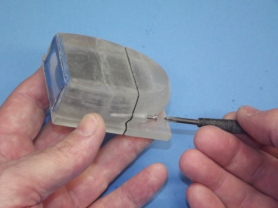
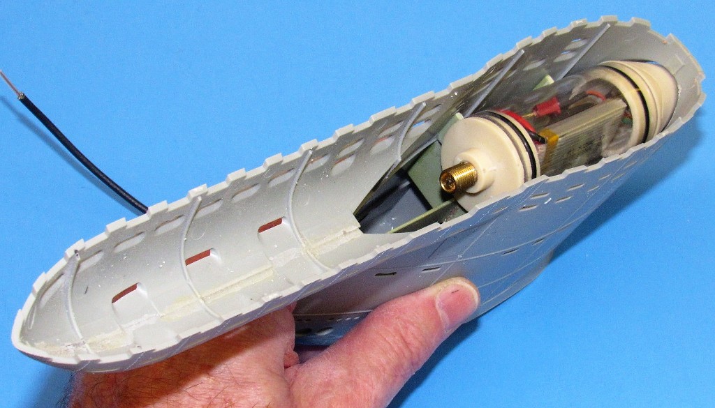
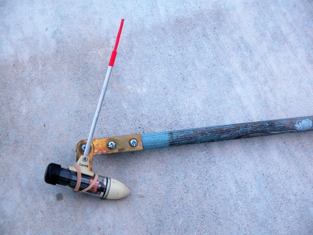
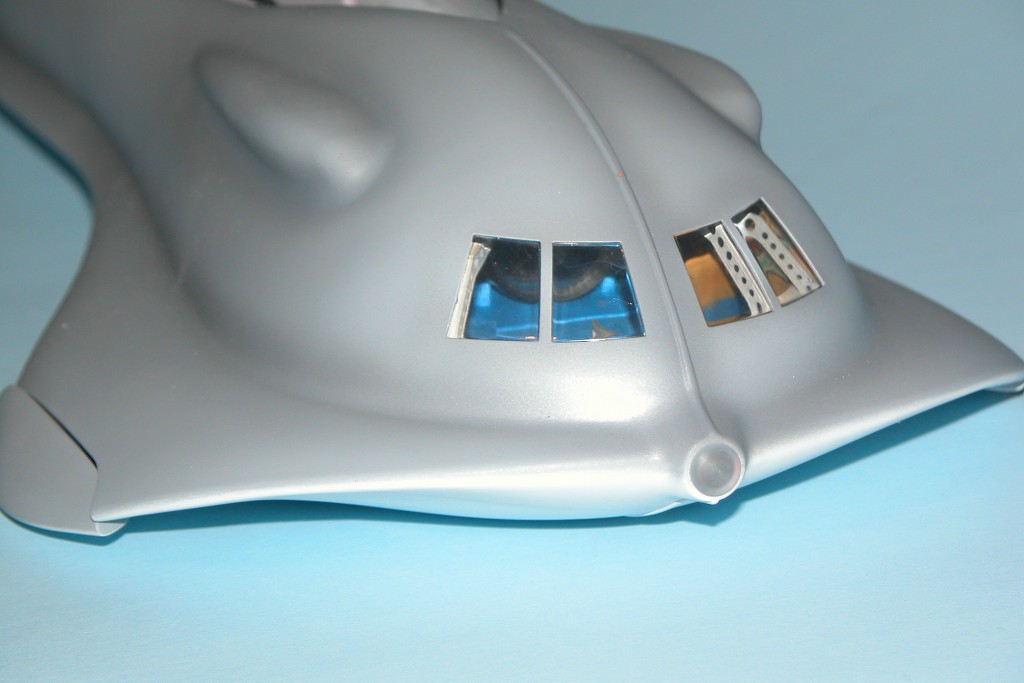
I'm with you on that, Andy. Here's an enclosure Tom Chalfant provided me to fit the 808-camera body style:
I modified the top of his enclosure to take rubber 'buttons' that would push down onto the top of the camera body to engage the function switches. This permits me to control camera operation without having to take the enclosure apart.

Just two machine screws needed to compress the two enclosure halves against the flange mounted gasket. Slick work, Tom!
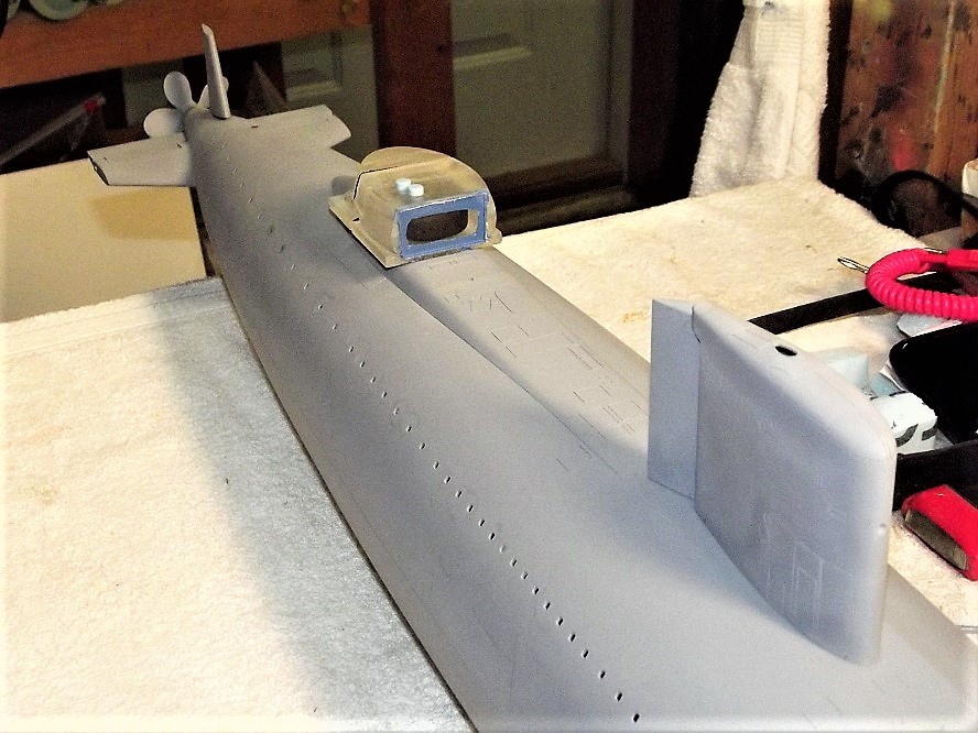
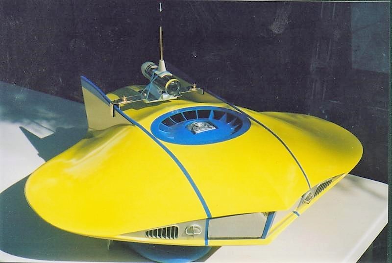
And, Andy, your super-neat tear-drop enclosure is a perfect fit within the 1/35 Type-23 sail!


David
Who is John Galt?Comment
-
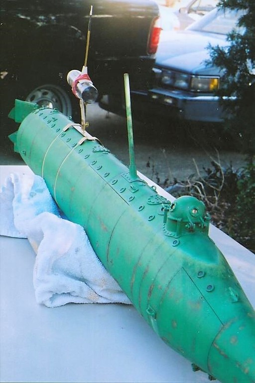
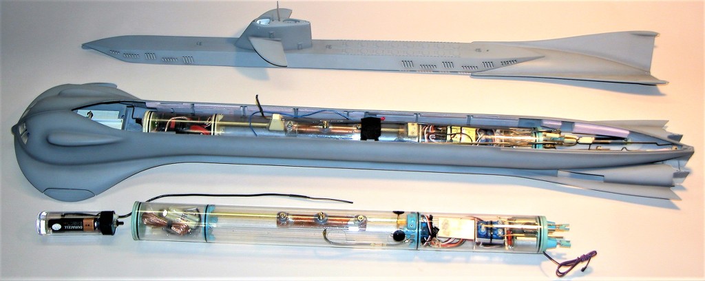
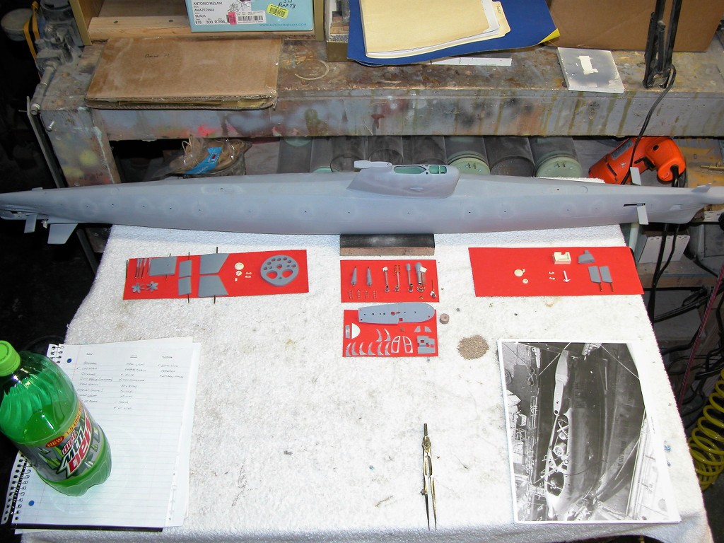
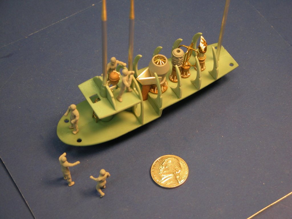
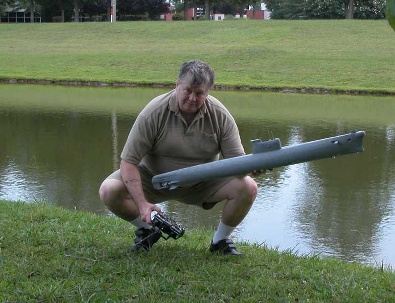
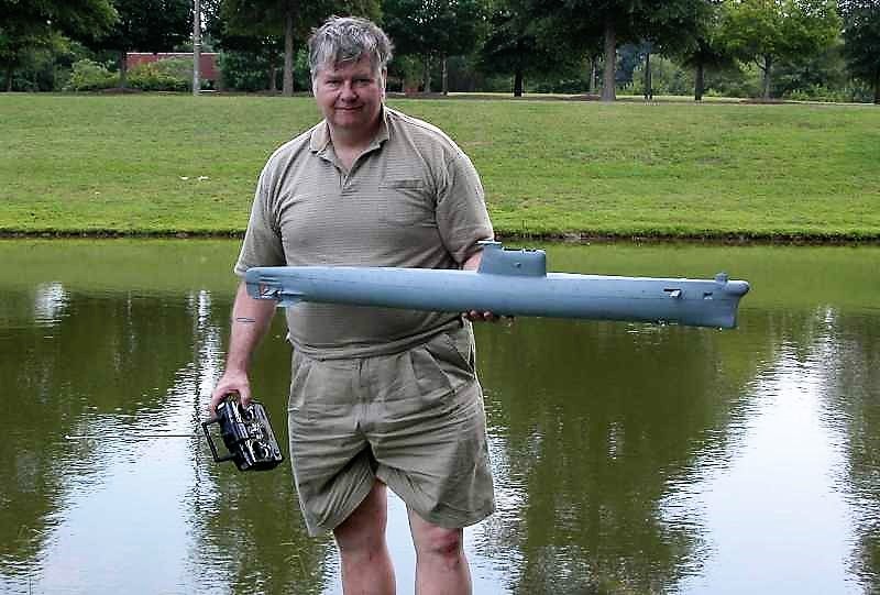
As this 1/35 Type-23 submarine plastic model kit was engineered by Bronco to be a display piece only, modifications -- in the form of internal structures to stiffen the hull and sail, as well as serving as foundations for the propulsion-control-variable ballast WTC and FPV camera-transmitter enclosure -- had to be performed to convert the model to a practical r/c submarine.
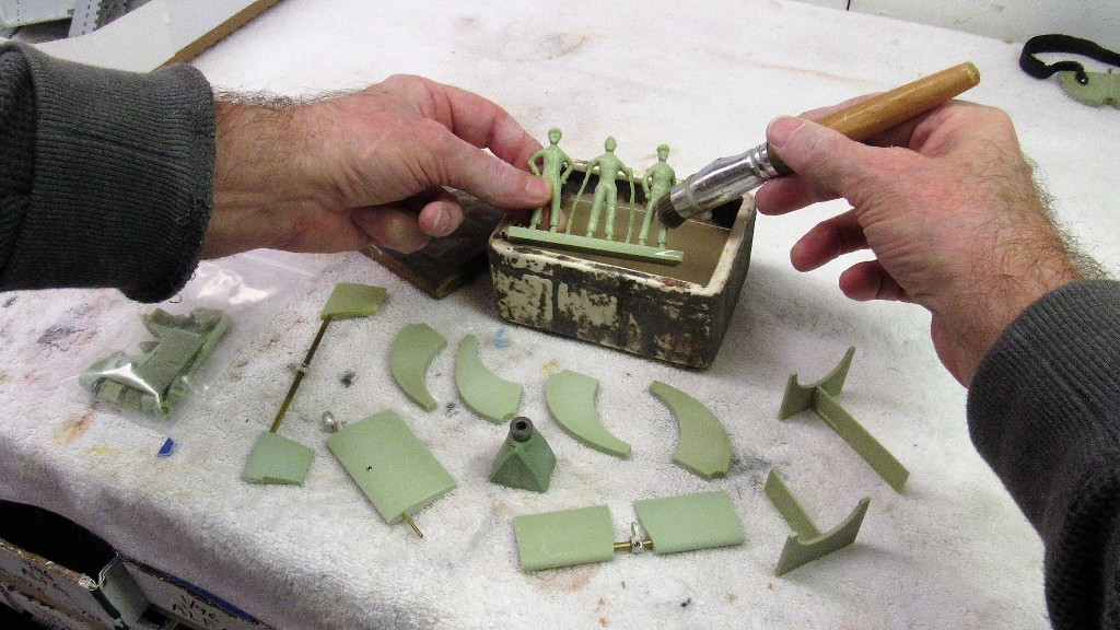
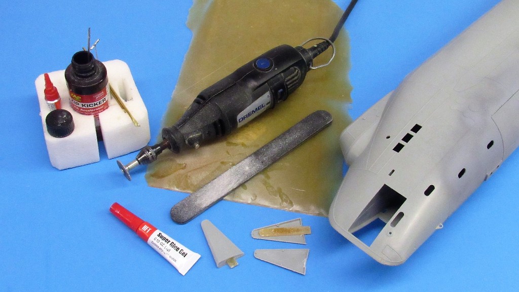
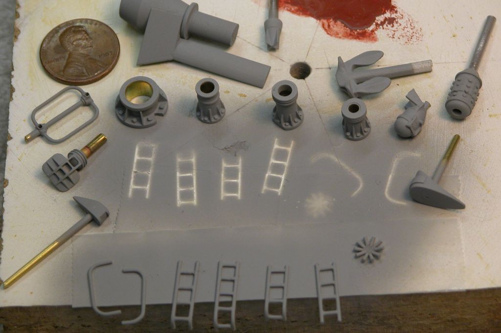
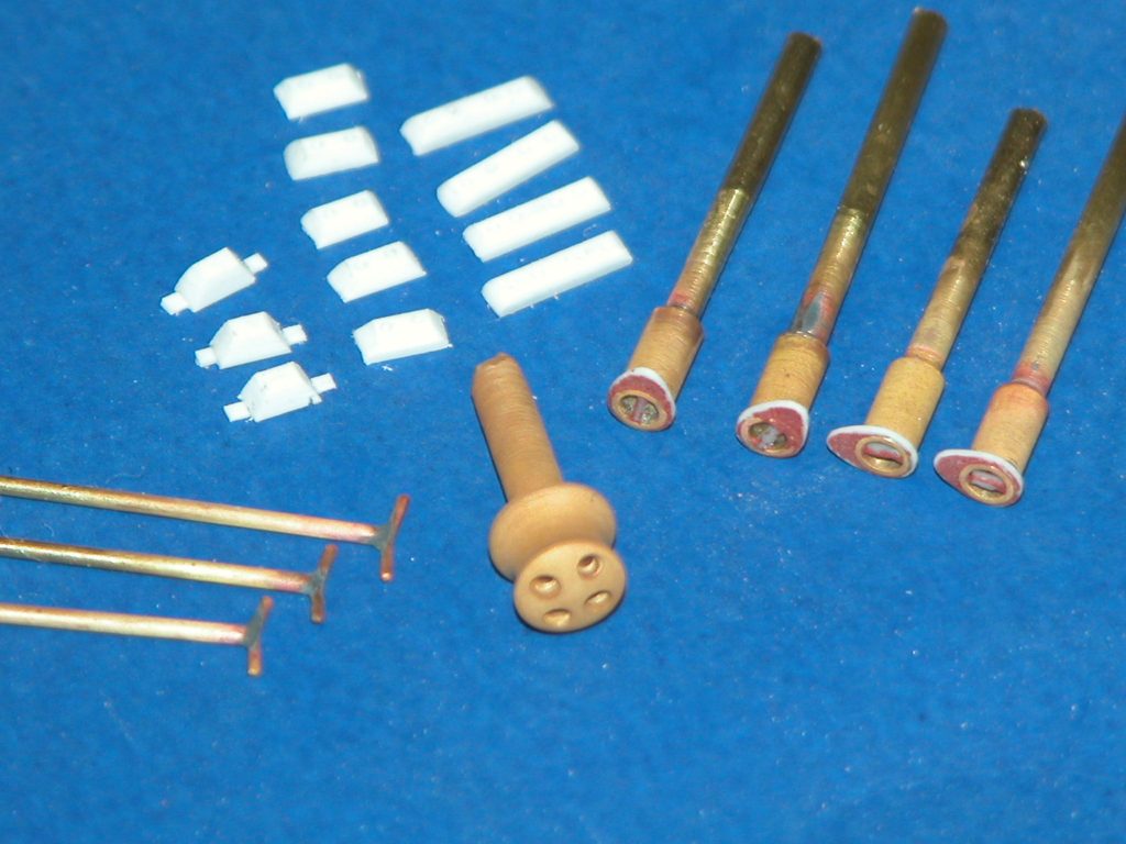
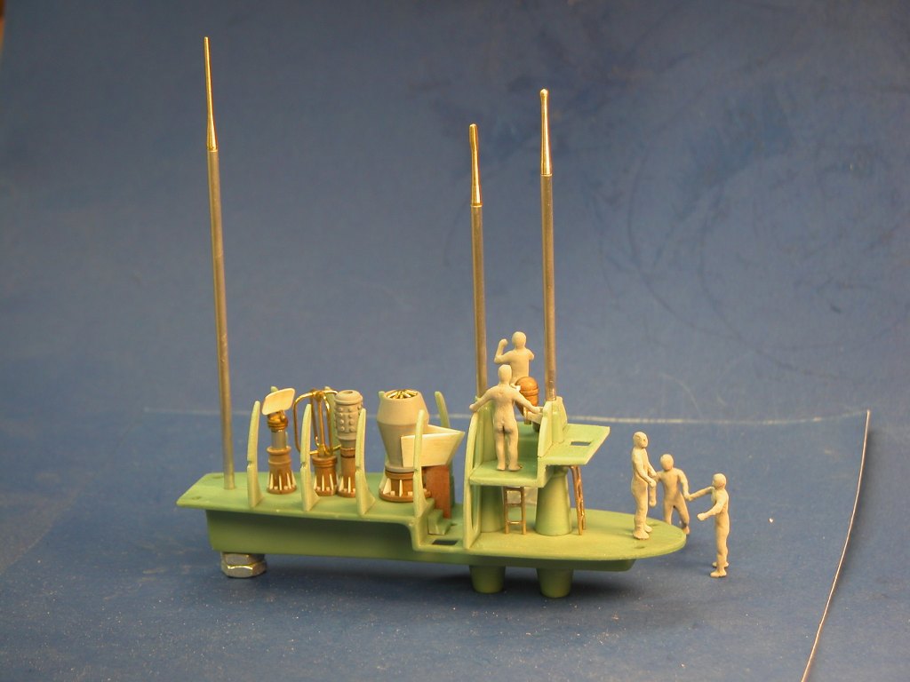
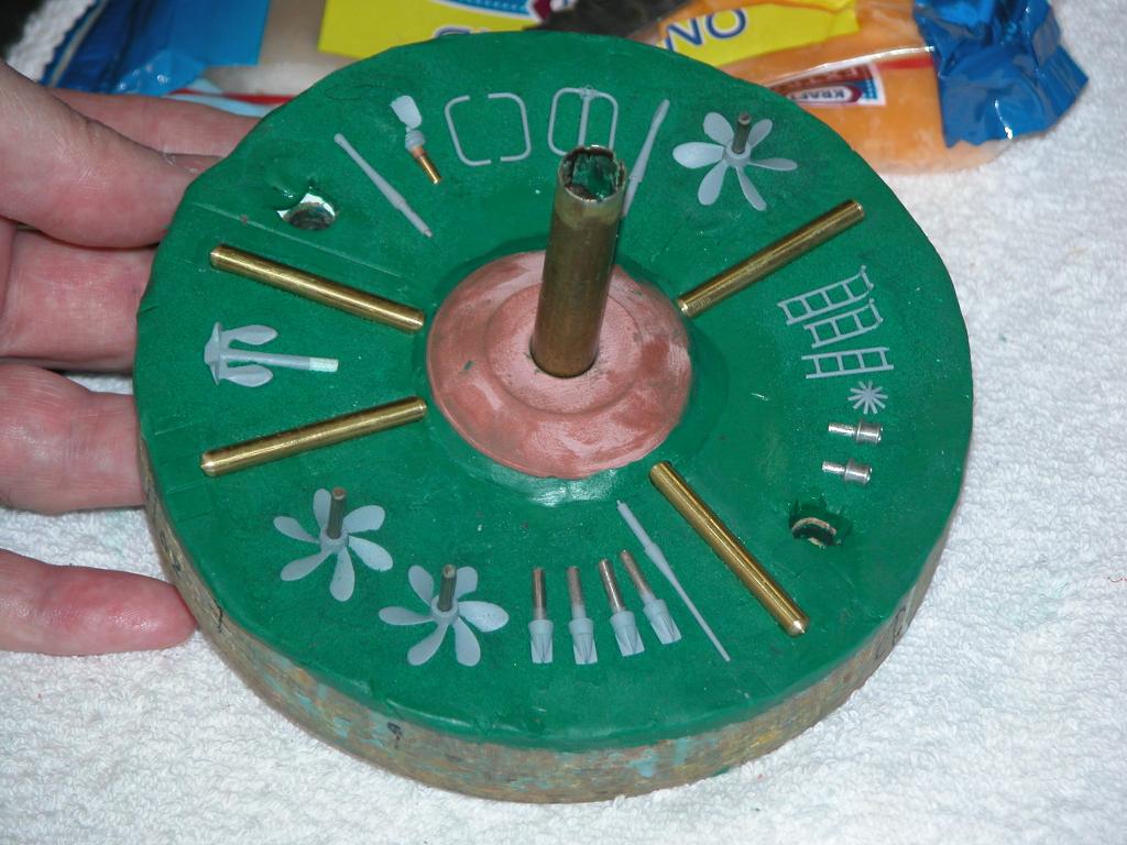
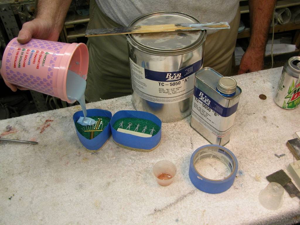
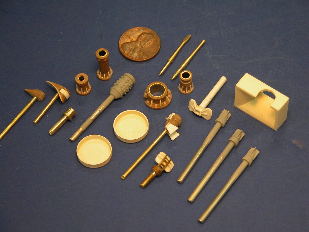
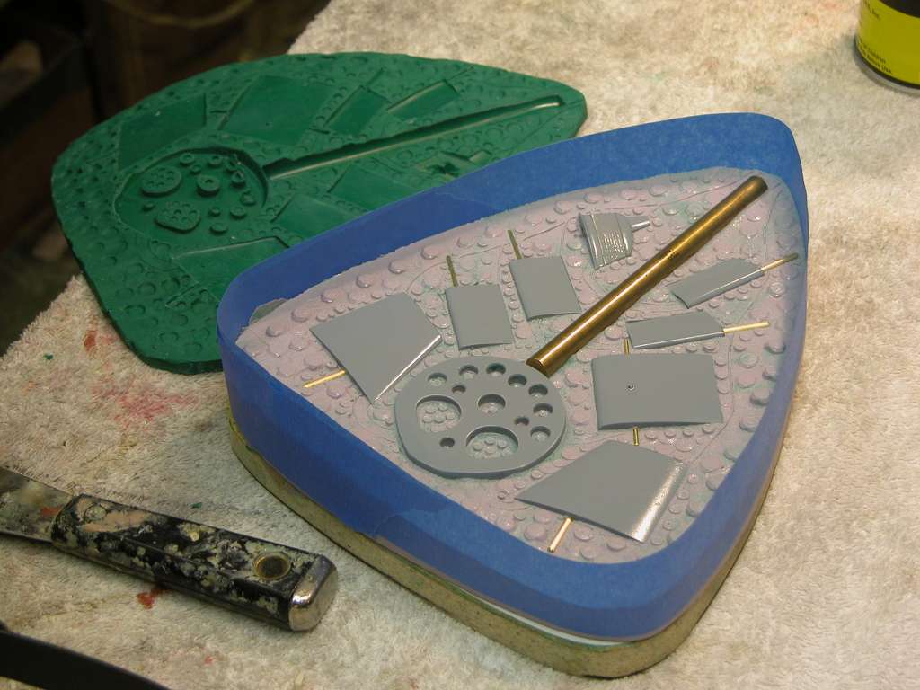
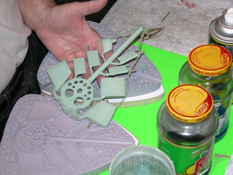
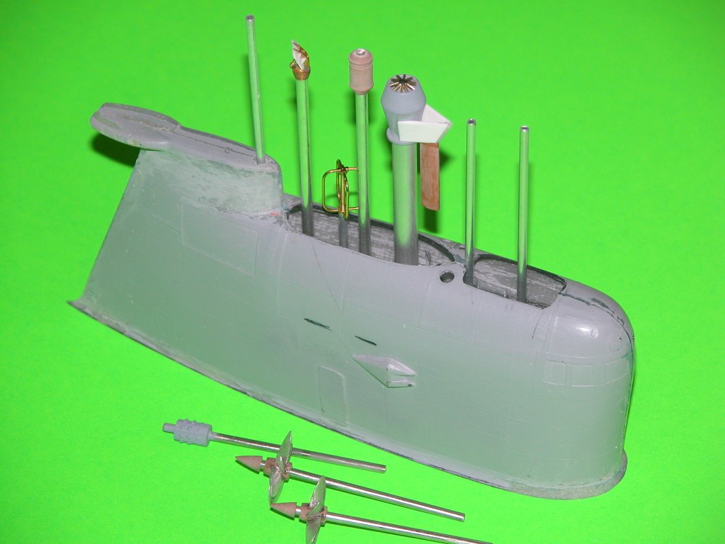
A while back I developed a 'fittings kit' for just this model kit. Most of the parts were cast polyurethane resin, and the rest cast white-metal. Before using any of the resin parts I first had to de-grease them with a dunking in lacquer thinner while scrubbing with an abrasive pad and stiff brush.
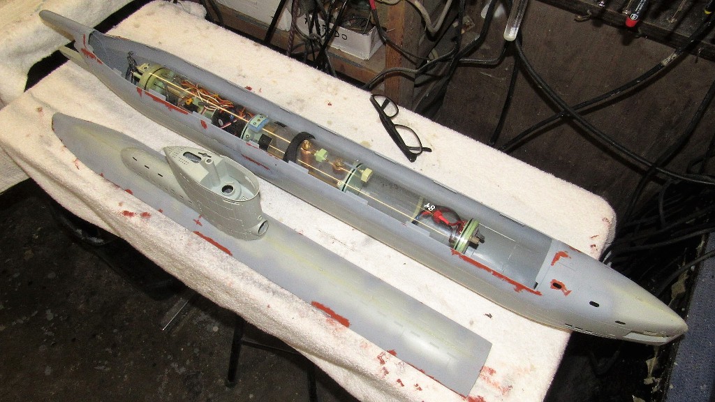
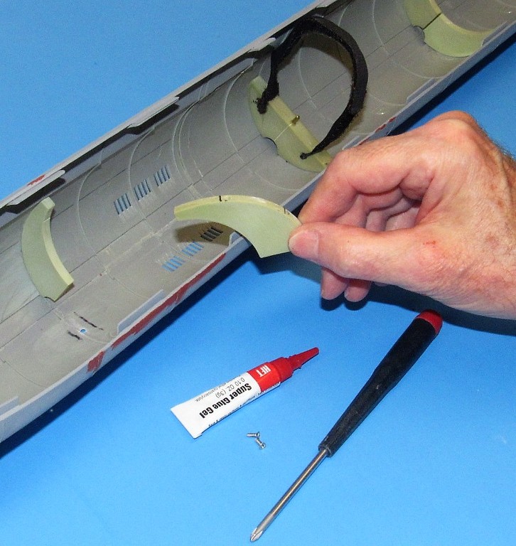
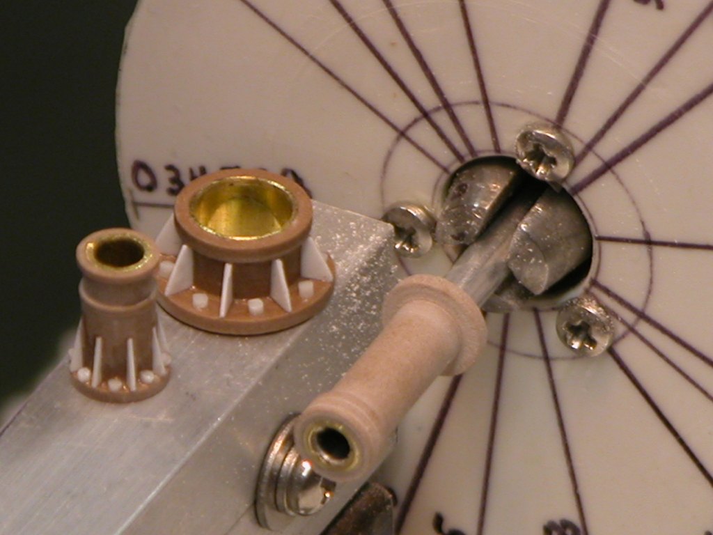
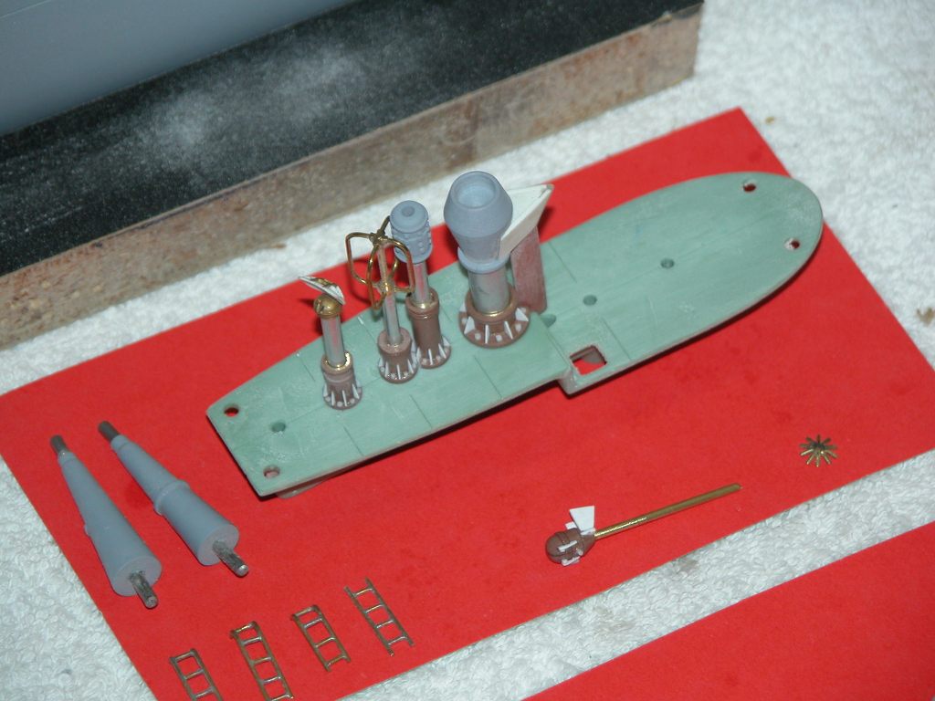
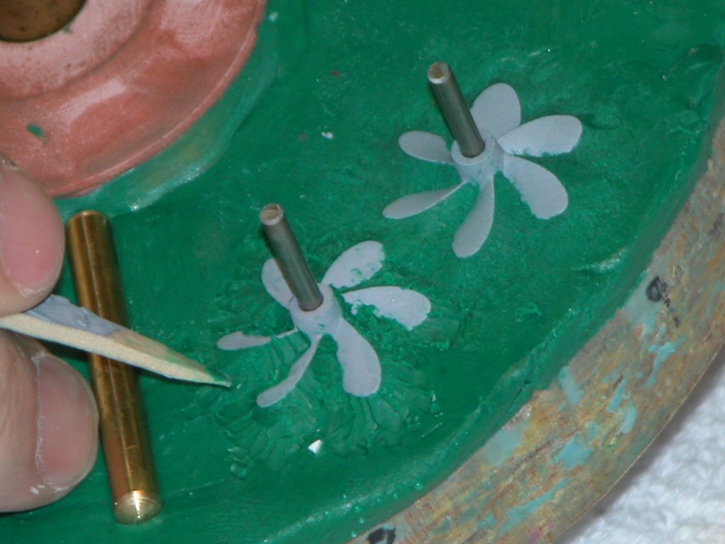
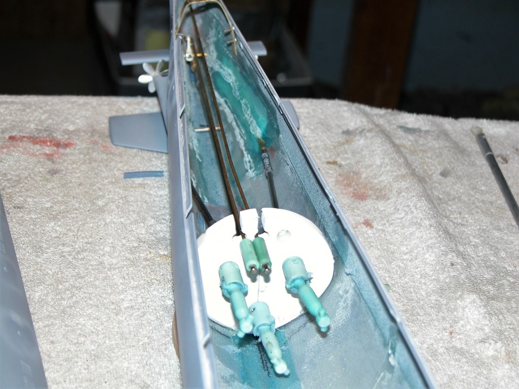
The WTC foundations were secured within the hull with both 2-56 machine screws and copious amounts of CA adhesive. First, each foundation segment was marked where a fastener hole would be bored, then I held the segment into a spot in the hull where it would go and marked the inside of the hull. That mark indicating where a hole would be drilled to pass the securing screw.
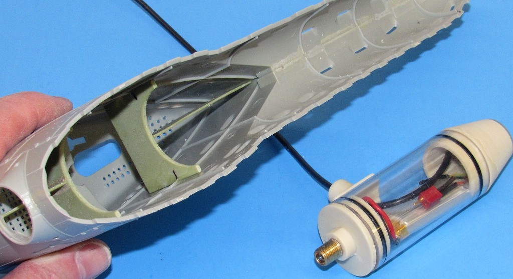
Note that the central foundation has a Velcro strap and an 'indexing pin'. The strap would hold the WTC in place, and the pin would insure that the cylinder was fixed against axial or rotation once mounted into the hull.
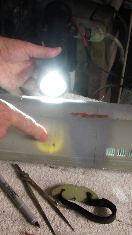
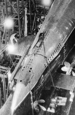
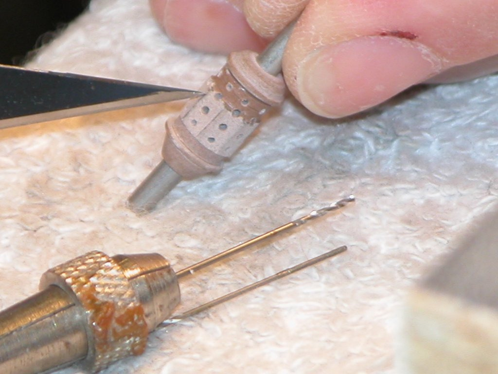
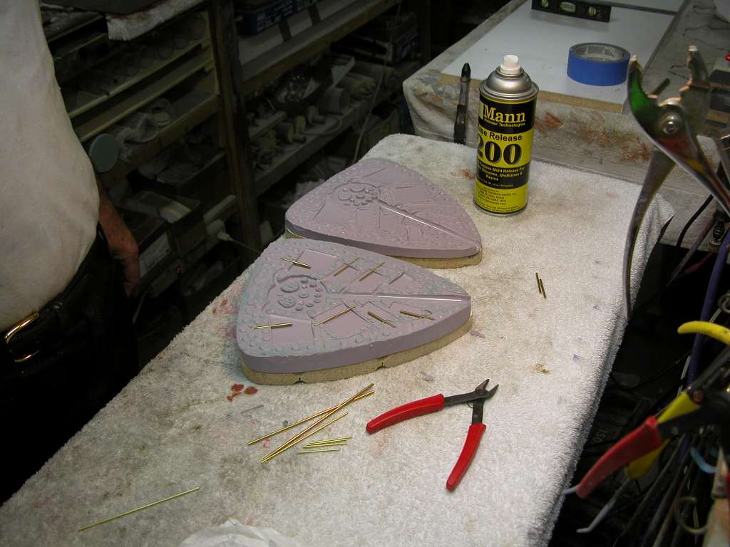
It was too awkward to drive a drill bit from within this hull. So, with the aid of a powerful flashlight, I identified the drill identification mark made on the inside and copied that marks location on the outside. Now I could drill the fastener holes from the outside with reasonable precision.
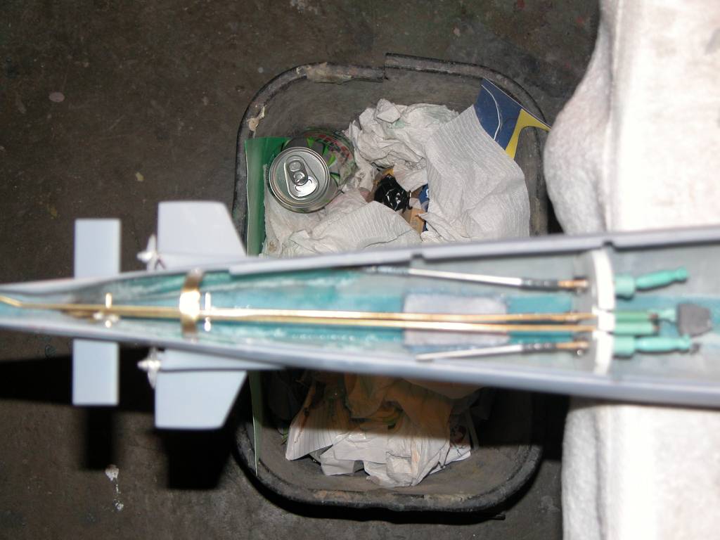
All hull foundation pieces were screwed tightly into place, and thin formula CA applied to secure the foundation pieces to the hull.
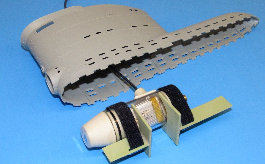
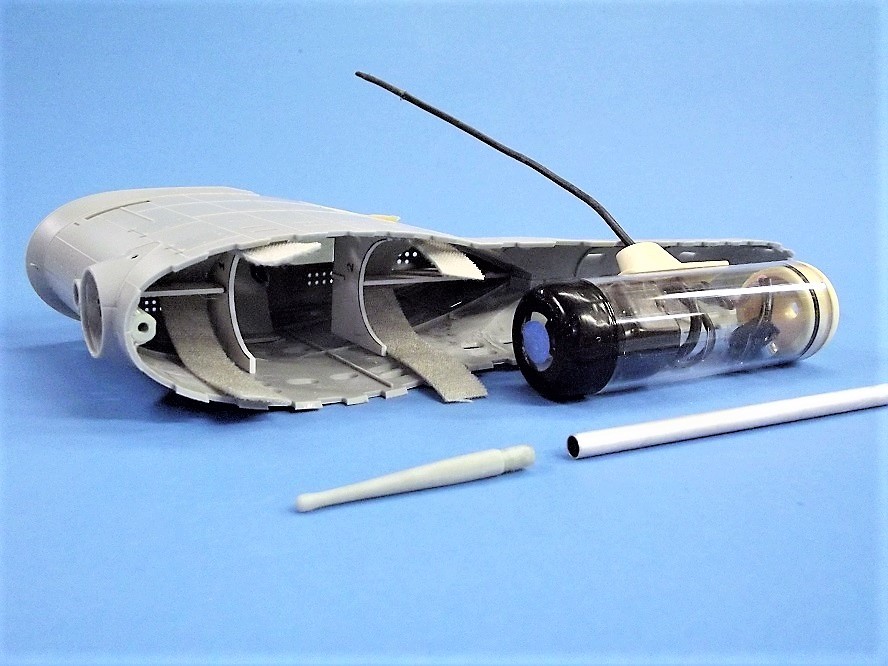
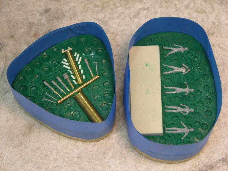
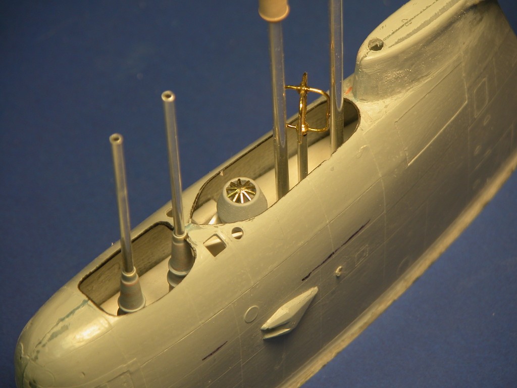
Two resin foundation pieces were secured within the sail. These not only provided an aligned platform for the FPV enclosure, they also greatly strengthened the entire sail assembly. Note how Velcro straps are used to secure the enclosure in place.
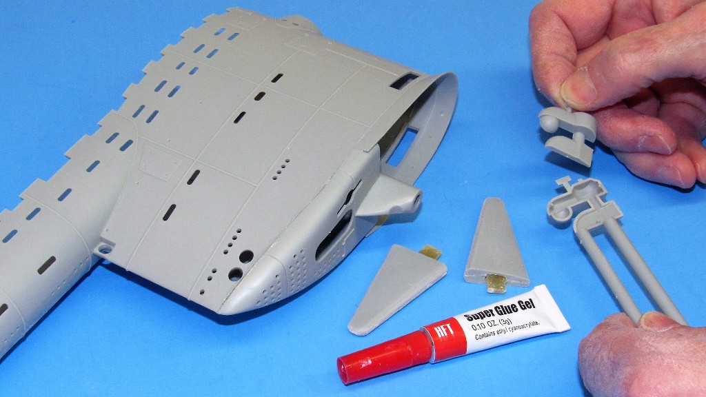
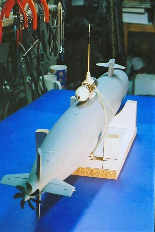
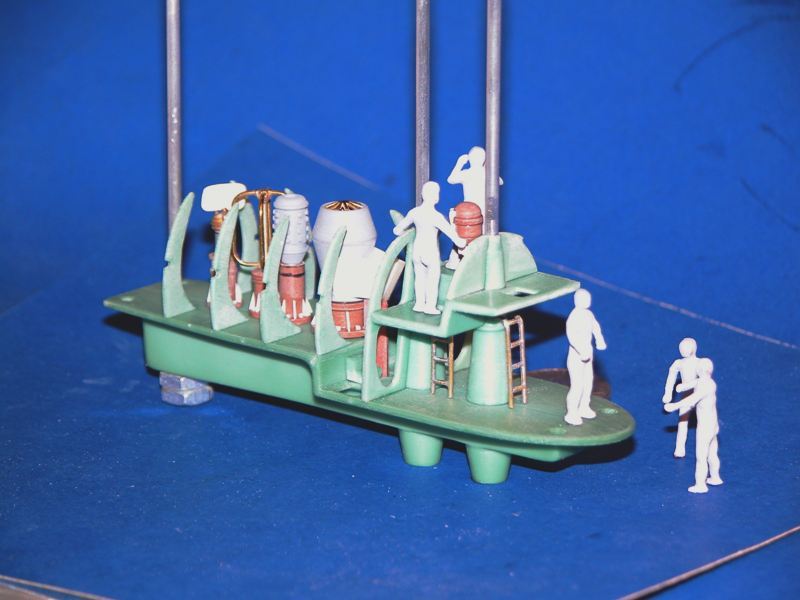
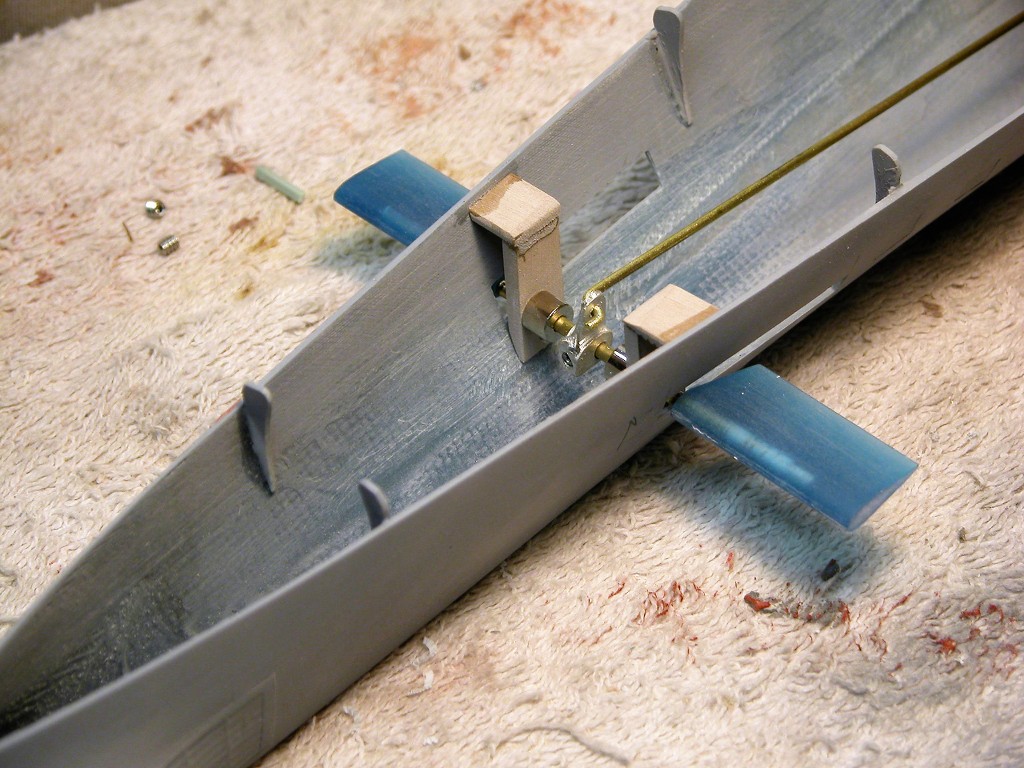
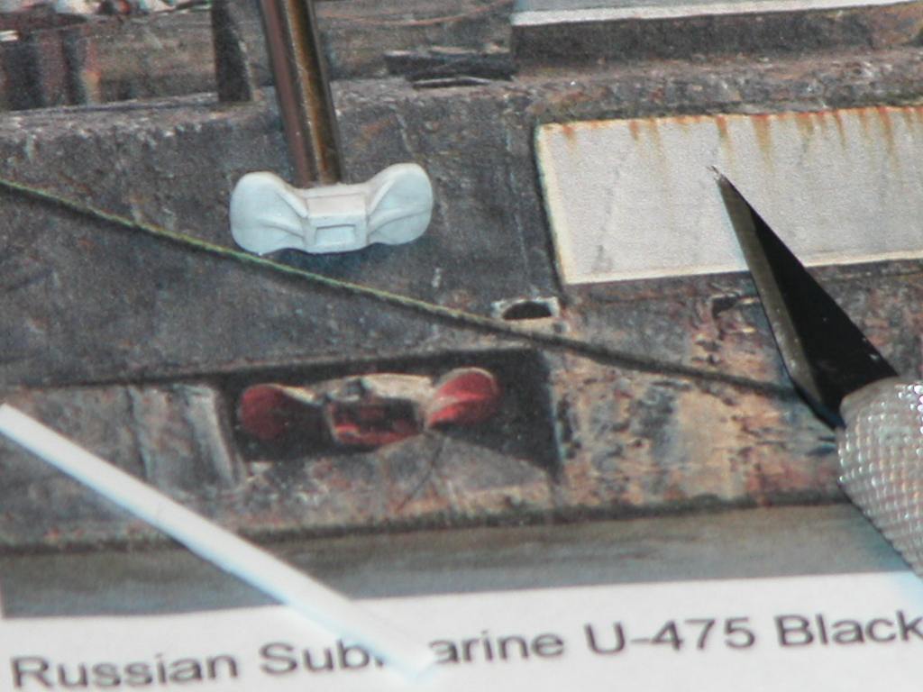
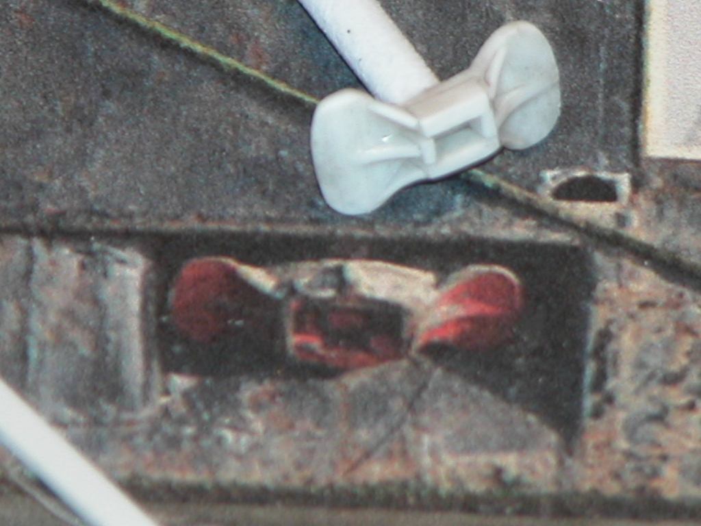
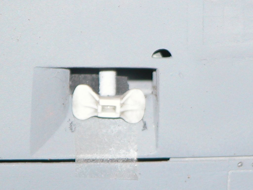
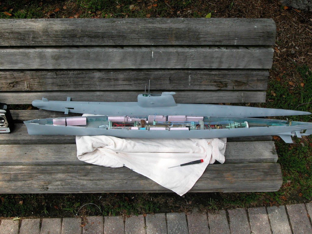
The rest of the kit parts were cleaned up and assembled. I modified the original two sets of horizontal control surface guards by equipping each with a strip of GRP sheet to act as an internal spar. The tabs of these items -- projecting from the end that mates with the hull -- would pass through square holes in the hull and affixed within to doubler-blocks on the inside, rendering these very vulnerable appendages with the strength needed to resist most collision and handling accidents without breaking.
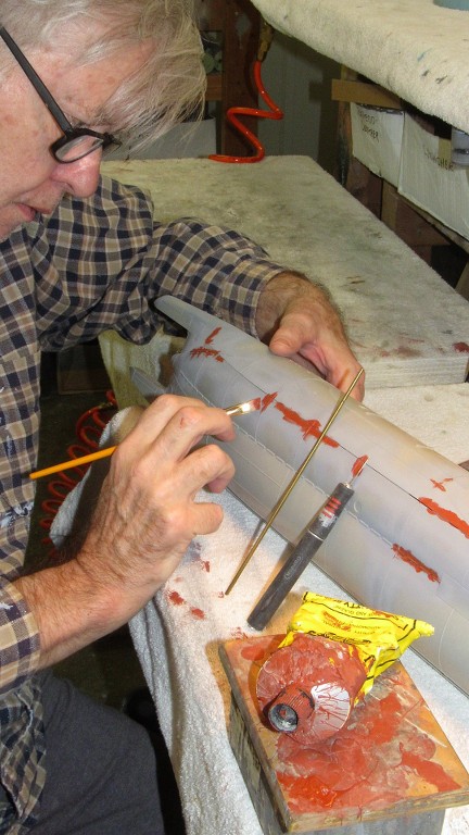
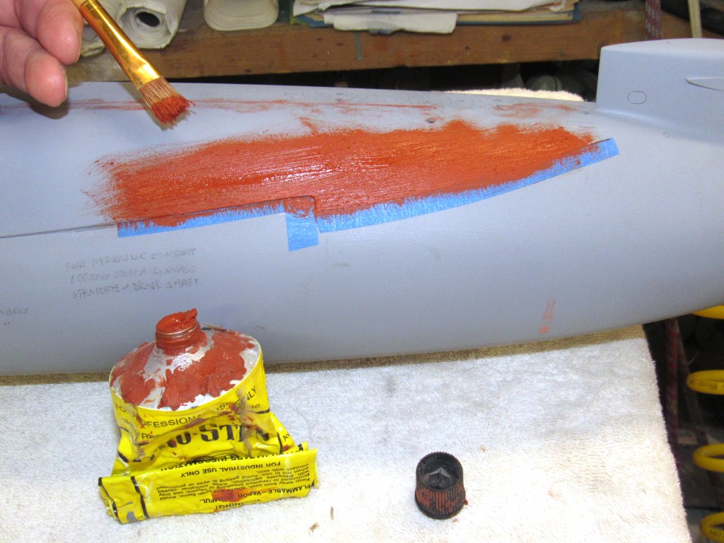
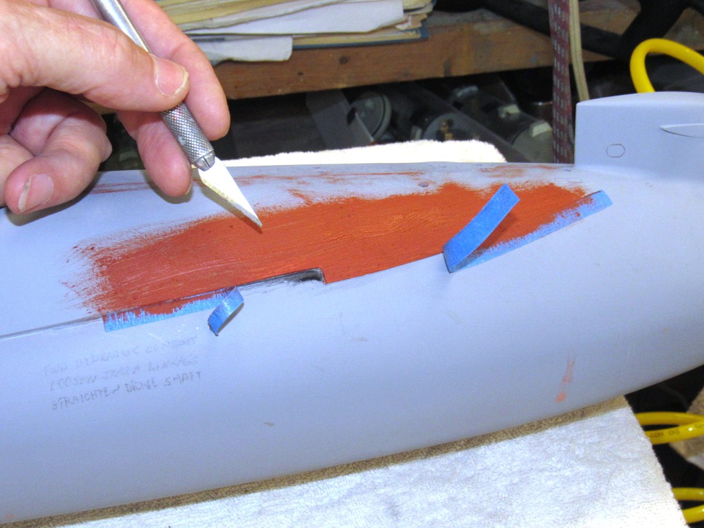
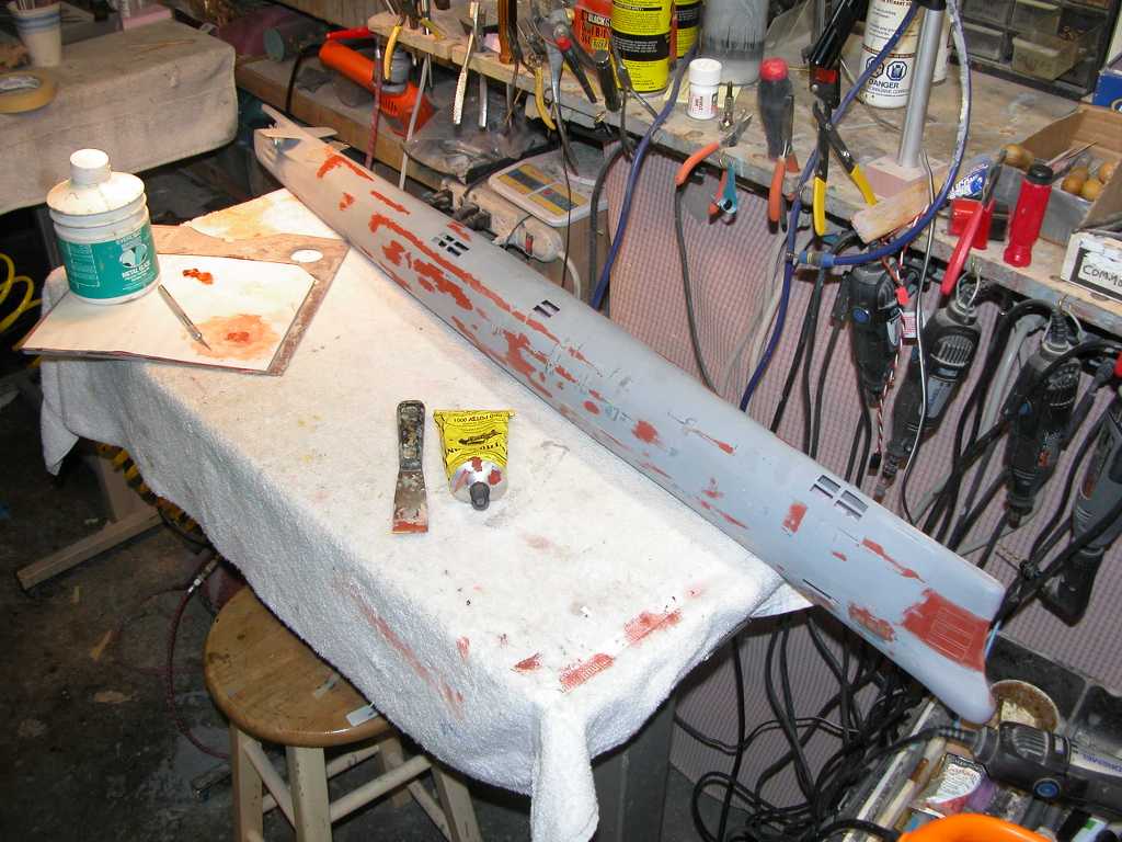
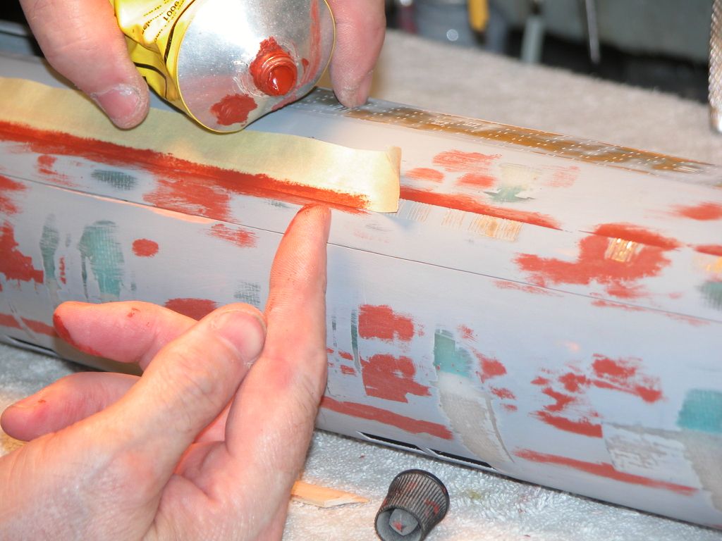
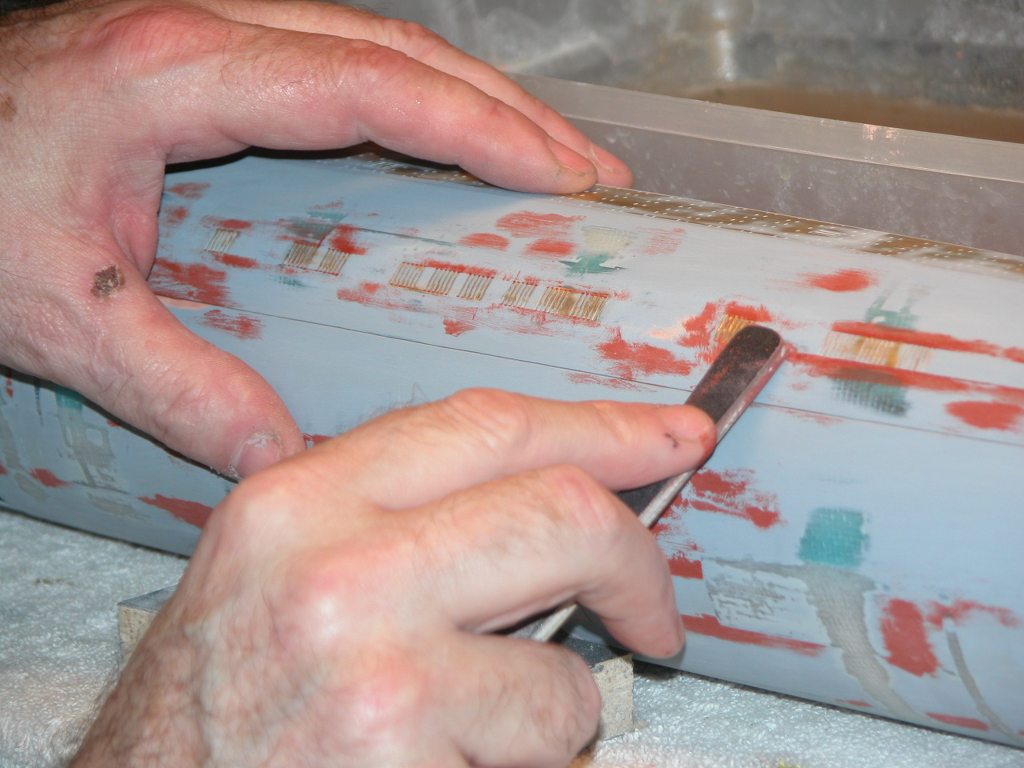
Meanwhile I continued the touch-up putty work, brushing it on to areas that still evidenced scratches, shallow gaps, and tool-marks.
Who is John Galt?Comment
-
Excellent.Of the approximately 40,000 men who served on U-boats in WWII, it is estimated that around 28,000 to 30,000 lost their lives.Comment
-
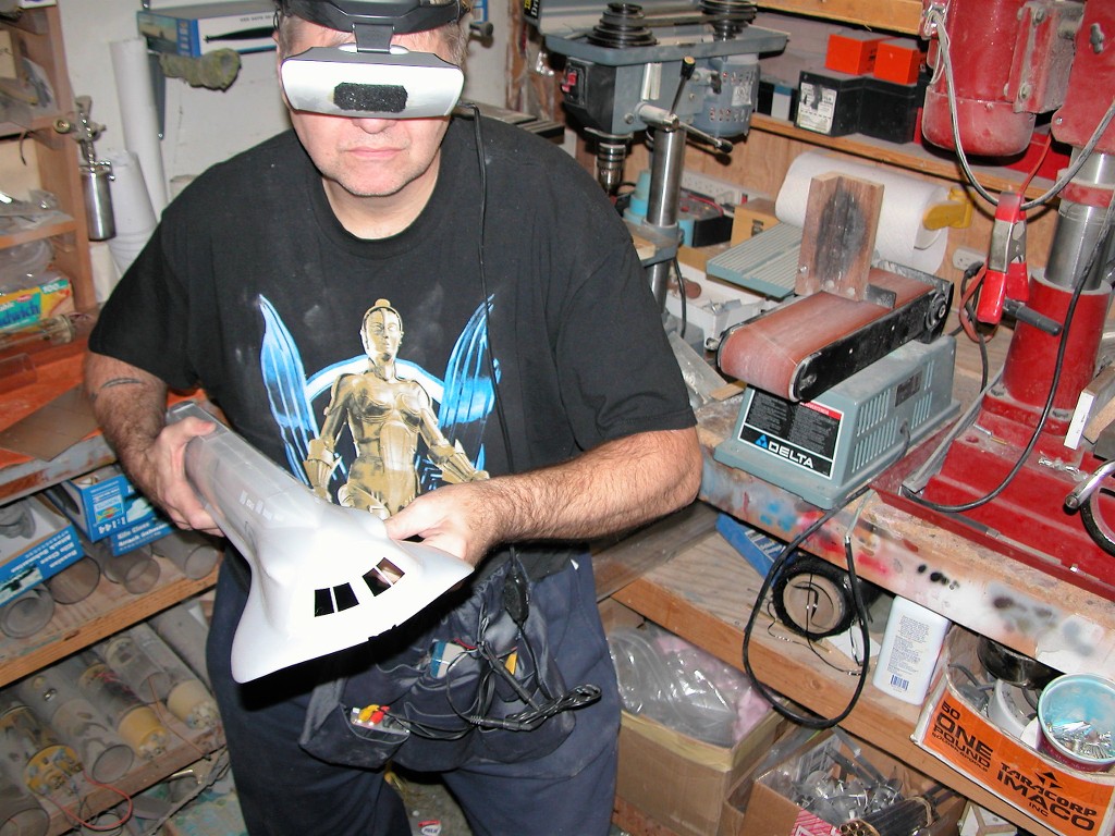
Great to see you at it with all the passion.Comment
-
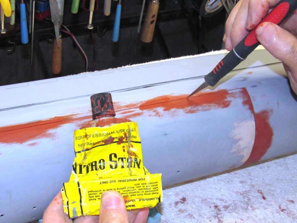
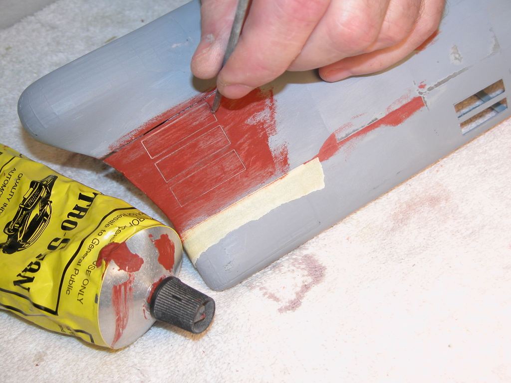
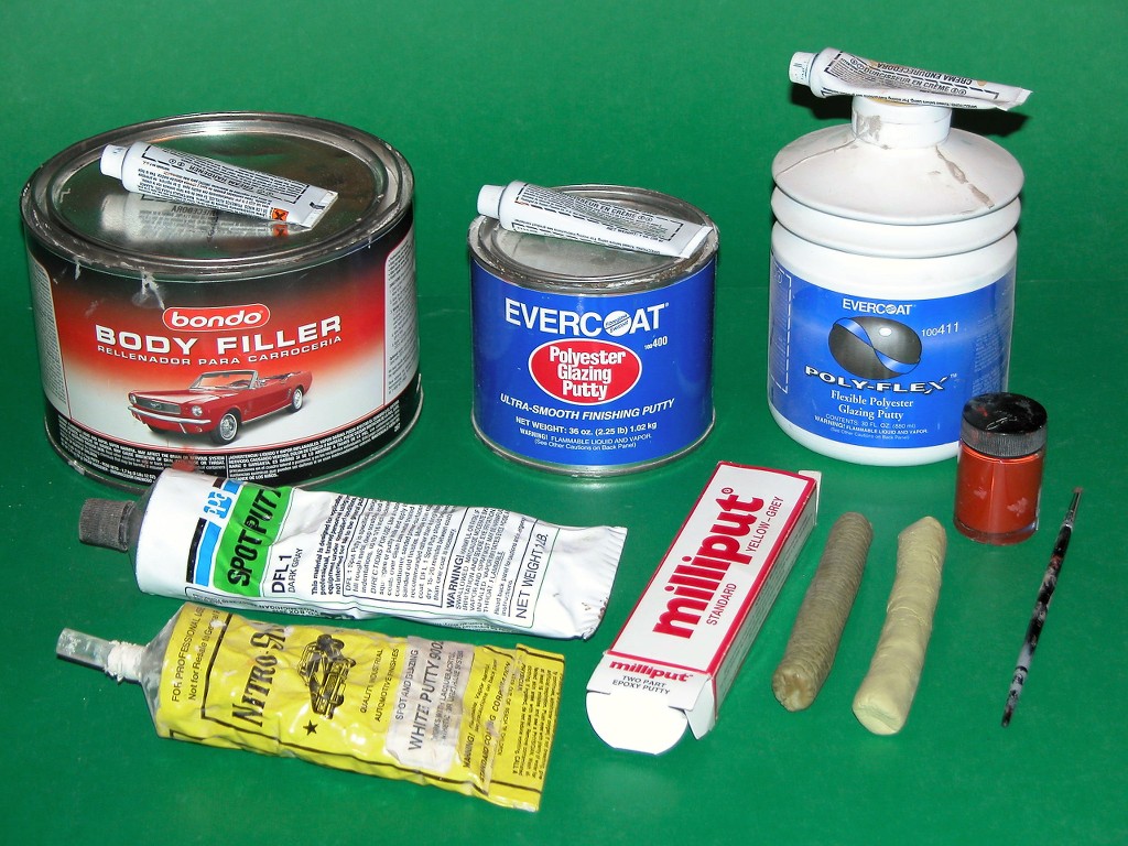
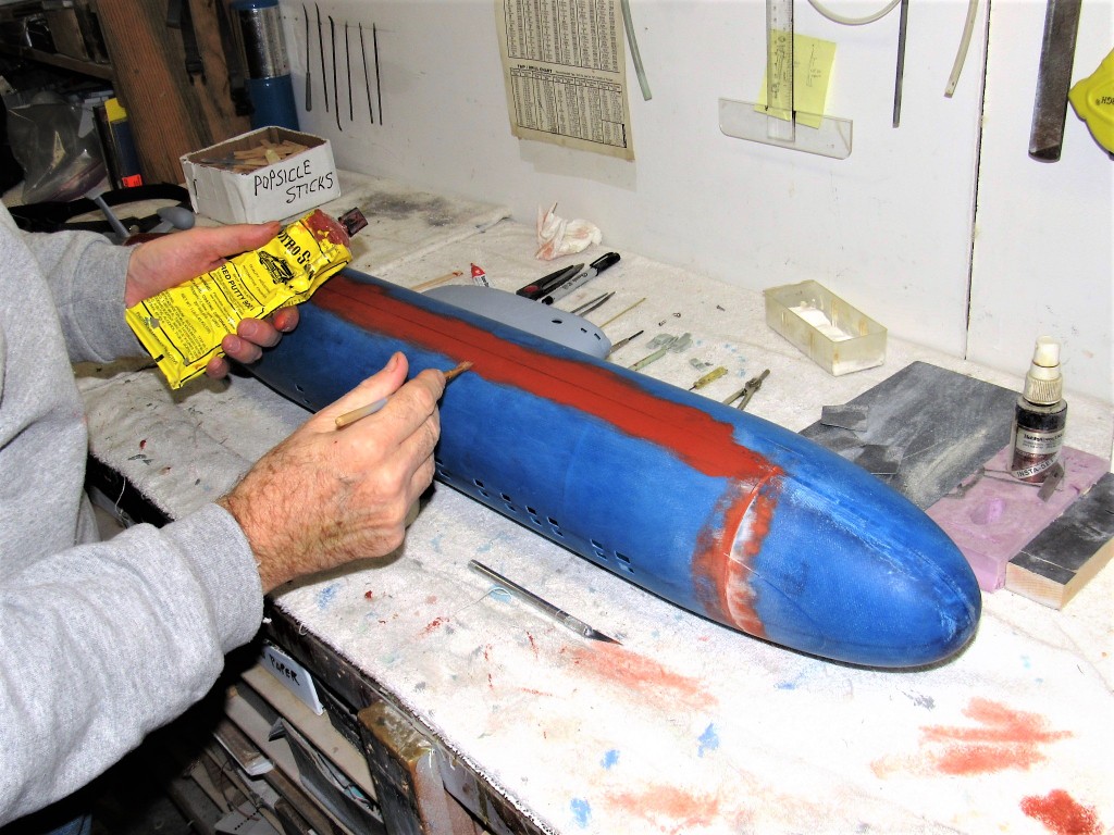
David, in the last picture, your NitroStan looks like a murder scene. LOL
Anyways, are you still filling in this photo or something else?
If you can cut, drill, saw, hit things and swear a lot, you're well on the way to building a working model sub.Comment
-
Yet another sacrifice to the God of Model Building. The Aztecs were ***** amateurs; hand me a #11 blade loaded tool, jack me up with three cups of coffee, add one wrong pull of the handle, and I'll splatter blood all over the shop.
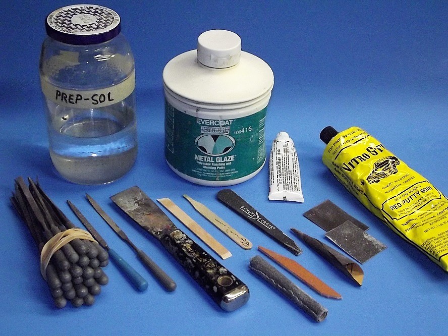
This is touch-up work. The initial filling was done with Bondo, and grout impregnated with CA, followed by filing, then heavy touch-up putty, then a wet sanding, followed by a heavy coat of primer. The work you see here is to fill the little imperfections that still present themselves in the primer. You know the drill, Tom: A good finish is a long, thankless job.
DavidWho is John Galt?Comment
-
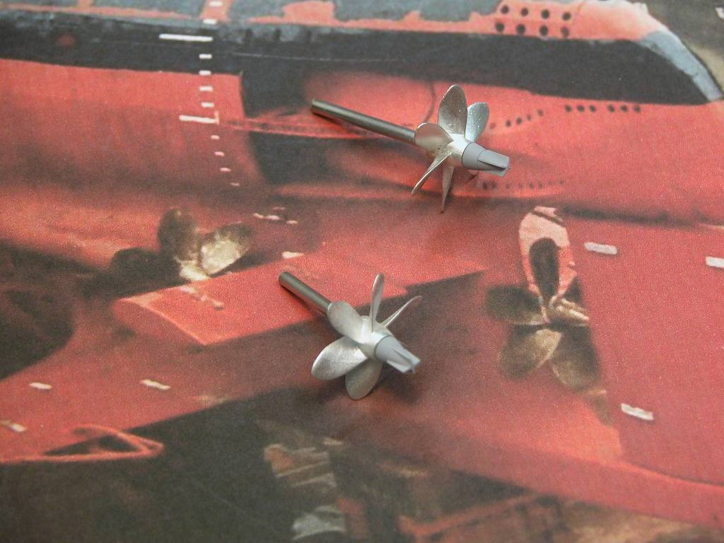
How many motors drove the 3 shafts?Make it simple, make strong, make it work!Comment
-
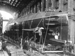
The Sierra I has 8 bow torpedo tubes while Sierra II has 6 tubes. Some references to share.
Sierra I:
Sierra II:
VComment


Comment