today's work

Collapse
X
 
  • Time
  • Show
Clear All
new posts
  • He Who Shall Not Be Named
    Moderator
    • Aug 2008
    • 12256


    As this 1/35 Type-23 r/c submarine will be little more than a mule to move the FPV (first person view) wireless video camera around underwater, I though it wise to give a little effort to the design and construction of the 1.25-inch diameter watertight enclosure needed to house the camera-transmitter, 1S Lithium-polymer battery, and magnetically actuated power switch.

    As with most gizmo's that originate here, the object began to take form while I was on the toilet. Thinking. In my head. In the head. Ah, sweet symmetry!

    From there, usually at my computer workstation (when not issuing blistering rants on the few forums I've yet to be banned from), I pause occasionally from keyboard pounding to scribble on whatever scraps of paper are at hand the raw idea; then refine the work onto post-it-note or graph-paper, at which point the drawing is to scale with critical dimensions called out.

    Simple structures like this enclosure warrant only a single orthographic side-view. More complicated structures get the three-view and isometric treatment.

    Such was the evolution of the FPV camera enclosure. Working drawing in hand and a quick trip to the shed garnered a proper length of Lexan tube and a removable bulkhead for the enclosures after end. Now all I have to do is work up the forward removable bulkhead that will house the camera and its lens. That will start life as a RenShape turned master, from which a rubber tool will be struck, and cast resin part(s) produced.

    But, first, I got to get this damned r/c model submarine done.


    Near the stern of the submarine, each side, are two rows of what I'll call (in the absence of any authoritative explanation) 'zincs'. Near the sawing, grinding, filing and sanding I did to separate the upper and lower hull halves some of these zincs were obliterated. Time had come to scratch-build and install the missing zincs.

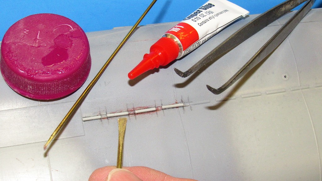
    Here you see the endgame: I'm finishing off the installation of the after set of zincs on the upper row, port side (the model is upside down).


    Each of the replacement zincs were a length of stretched-sprue CA'ed in place after laying out their position and spacing with a pencil.


    The kit provided the sprue, which I heated and stretched while semi-molten. An acquired art. The amount of heat, over such and such an area, with just so much tension applied, and that tension throttled till the desired diameter is achieved and halted till the plastic once again assumes a solid state. Much good fun. If you don't burn yourself... you're simply not trying hard enough!


    CA was applied with tools, not directly from the tube. Here I'm using a spatula type application tool to drive the adhesive along the length of a zinc, bonding it securely to the hull.


    A fault with the kit design was Bronco's attempt to capture the oval shaped upper limber holes (the function of limber holes is to vent and flood the spaces between inner and outer hull) at a high draft-angle of the injection forming tools hull cavity. To prevent entrapment, they made the wall thickness so thin at the extreme draft-angle point (near the top of the hull) that a complete fill during the injection of the molten polystyrene was not achieved and the resulting openings were miss-formed. That had to be fixed!

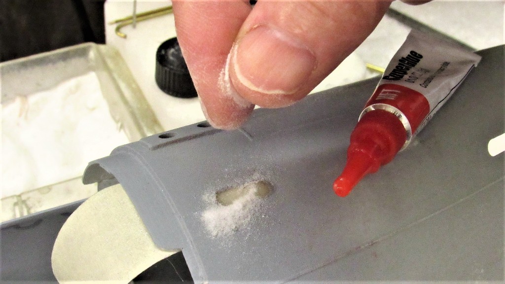
    I skinned over these holes with a CA-baking soda grout, then ground out properly shaped limber holes. This started with blanking off the hole from the inside with some masking tape.


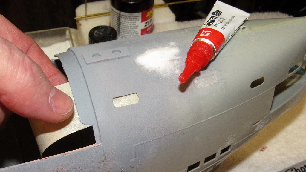
    CA was squirted over the masking tape and run up to wet the edges of the hole. Then baking soda was sprinkled on. The high pH of the baking soda catalyzed the CA almost immediately. This build-up continued till the hard grout was well over the contour of the bow.


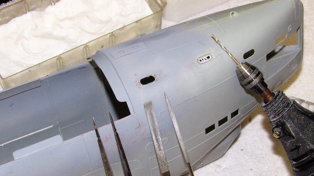
    Before going to town with rasp and second-cut file I outlined around the grout with a pencil. The pencil hashing would tell me to stop with the file work. To the right is a contoured grout filled hole that has already been marked, with the aid of a stencil, to indicate the desired shape of the 'new' limber hole.


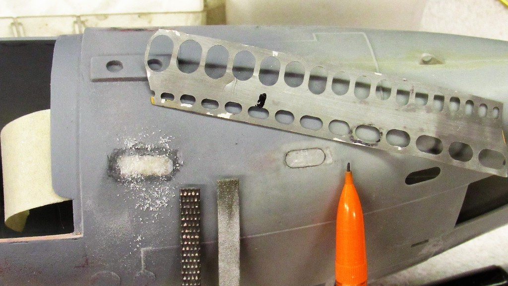
    To the right is how I make the rough-cut to the limber hole -- using a 1/16-inch drill bit as a hand-held mill. To the left you see a finished limber hole, given final form with careful use of flat and round diamond files. Nothing to it!


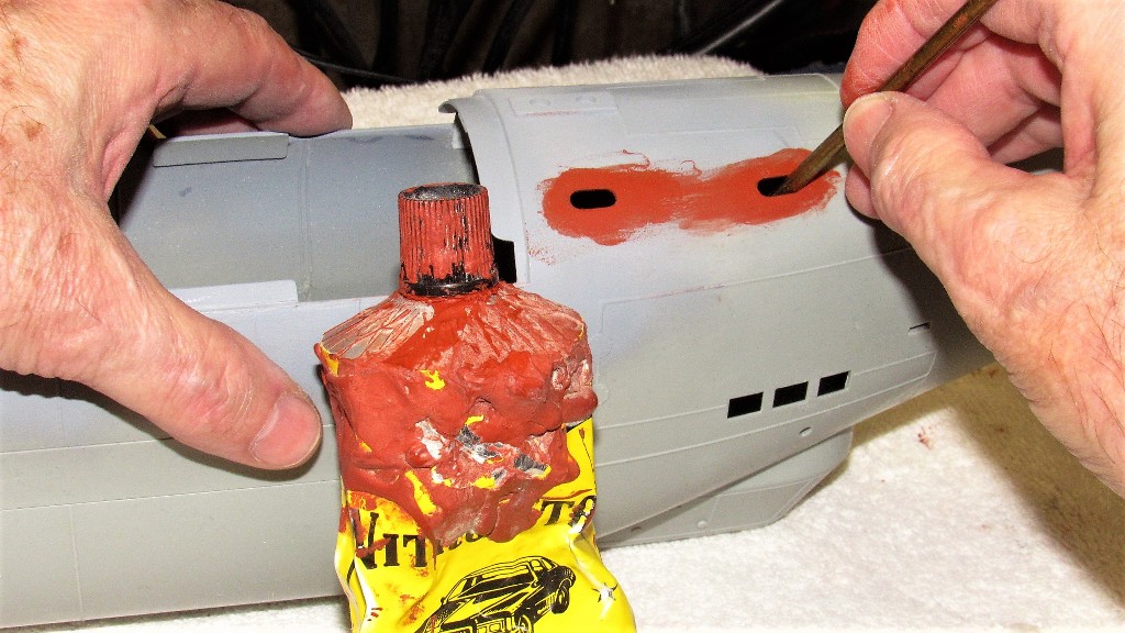
    Invariably there will be pits and scratches around the work, so I rub in some touch-up putty. I permit the putty to get onto the inside edges of the limber holes. That still pliable putty is then pushed into the edges with a rod of a diameter slightly smaller than the width of the limber hole. The rod is swished around a bit and pulled out. Once the putty dries, the surface is wet-sanded and primed.


    Who is John Galt?

    Comment

    • He Who Shall Not Be Named
      Moderator
      • Aug 2008
      • 12256

      Originally posted by Monahan Steam Models
      Alright already. Let’s see it ******, what have you been holding out on us with your progress!
      ... fresh off the presses!
      Who is John Galt?

      Comment

      • Monahan Steam Models
        Captain
        • Apr 2020
        • 755

        Originally posted by He Who Shall Not Be Named

        ... fresh off the presses!
        Yeah I was wondering if you were going to address those forward limber holes or not in this build. I rest my critique for now. You have passed… LOL

        Comment

        • He Who Shall Not Be Named
          Moderator
          • Aug 2008
          • 12256

          Originally posted by Monahan Steam Models

          Yeah I was wondering if you were going to address those forward limber holes or not in this build. I rest my critique for now. You have passed… LOL
          Yup. Those are eyesores. But other than that, this is a wonderfully researched, engineered, and rendered box of parts. I so wish Bronco would consider doing other 'big scale' injection formed kits like this.

          David
          Who is John Galt?

          Comment

          • redboat219
            Admiral
            • Dec 2008
            • 2735

            Where can we get one of those templates?

            Just in case, what's the dimensions of the new limber holes?
            Make it simple, make strong, make it work!

            Comment

            • He Who Shall Not Be Named
              Moderator
              • Aug 2008
              • 12256

              Originally posted by redboat219
              Where can we get one of those templates?

              Just in case, what's the dimensions of the new limber holes?
              verlindon stensils - Search (bing.com)
              Who is John Galt?

              Comment

              • redboat219
                Admiral
                • Dec 2008
                • 2735

                Product discontinued...

                Guess one can always improvise using brass sheet or even a soda can.

                Carry on.
                Last edited by redboat219; 01-23-2022, 01:05 AM.
                Make it simple, make strong, make it work!

                Comment

                • MFR1964
                  Detail Nut of the First Order
                  • Sep 2010
                  • 1290

                  I hope you've encountered the fact that those limberholes are not symmetrical placed at both sides, otherwise there is more work to do.

                  Manfred.

                  I went underground

                  Comment

                  • He Who Shall Not Be Named
                    Moderator
                    • Aug 2008
                    • 12256

                    Originally posted by MFR1964
                    I hope you've encountered the fact that those limberholes are not symmetrical placed at both sides, otherwise there is more work to do.

                    Manfred.
                    Argh!

                    Manfred!... you taskmaster, you!
                    Who is John Galt?

                    Comment

                    • MFR1964
                      Detail Nut of the First Order
                      • Sep 2010
                      • 1290

                      You're lucky, it's the other side you have to change, i'll search for some pics to give you some reference.

                      Msnfred.
                      I went underground

                      Comment

                      • He Who Shall Not Be Named
                        Moderator
                        • Aug 2008
                        • 12256

                        Originally posted by MFR1964
                        You're lucky, it's the other side you have to change, i'll search for some pics to give you some reference.

                        Msnfred.
                        Manfred to the rescue! Thank you, old friend.

                        David
                        Who is John Galt?

                        Comment

                        • MFR1964
                          Detail Nut of the First Order
                          • Sep 2010
                          • 1290

                          Close both holes on the other side, start halfway the second closed hole, measure the width between your modified holes, and you're good to go.

                          Click image for larger version  Name:	P3260208.JPG Views:	0 Size:	42.3 KB ID:	158367

                          Not many pics present, but here is the idea, a shot of the bow-aeria.

                          Manfred.
                          I went underground

                          Comment

                          • He Who Shall Not Be Named
                            Moderator
                            • Aug 2008
                            • 12256

                            Ah, nuts! You're right, they stager longitudinally from each side. Screw it, I'm going with what I've got. At some point you have to be pragmatic and accept the occasional out-of-scale item like these limber hole locations.

                            I so appreciate your effort and time, Manfred. But I must move on -- I have so many obligations to get off the wall and benches...

                            David
                            Who is John Galt?

                            Comment

                            • MFR1964
                              Detail Nut of the First Order
                              • Sep 2010
                              • 1290

                              Sissy!!!!!!

                              If you like more work, the barriers near the stern are vertical instead horizontal, same issue at the ballast intakes near the keel, they are vertical has to be horizontal, near the torpedo doors you can choose between three holes or seven holes, barriers are horizontal, mine has the seven holes, more a matter of choice, they used both variations.

                              Manfred.

                              Captain Details
                              I went underground

                              Comment

                              • Das Boot
                                Rear Admiral
                                • Dec 2019
                                • 1149

                                Of the 40,000 men who served on German submarines, 30,000 never returned.”

                                Comment

                                Working...