today's work

Collapse
X
 
  • Time
  • Show
Clear All
new posts
  • trout
    Admiral
    • Jul 2011
    • 3545

    You want fun? Come to next year's SubFest and run around the pond/pool with David. That is a hoot! Even if you do not run a sub, the camaraderie and putting faces to names is worth the ticket. I can die tomorrow and I will have a smile on my face for attending Subfest 2021. Meeting David, Ken, Steve, Bob, Nathan, Warren, Casey, Erik, and the list goes on was one of the best parts.

    Maybe we can get a Texas run soon?

    Anyways, carry on and keep surfacing.
    Last edited by trout; 10-20-2021, 07:02 PM.
    If you can cut, drill, saw, hit things and swear a lot, you're well on the way to building a working model sub.

    Comment

    • SteveNeill
      Commander
      • Apr 2020
      • 315

      Will we ever have such an event in California? I'd love to go to the SubFest next year. But I don't have a plane to fly there and driving cross country in my motor home would be a hardship. I have a studio to run.

      Comment

      • He Who Shall Not Be Named
        Moderator
        • Aug 2008
        • 12253


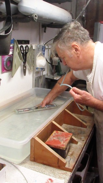
        Well, after about two-weeks of work I got this little HUNLEY WTC to work as advertised. Here I'm doing a practical in-water test of the systems ballast sub-system. The hose under my thumb leads to the suction side of the Low Pressure Blower (LPB) diaphragm pump. When the inlet side of that hose is in the air, such as when the model submarine broaches the surface in preparation to surfacing, the LPB is turned on, compressing air and blowing it into the flooded ballast tank, blowing out the water, lightening the boat, causing it to surface and assume surfaced trim.

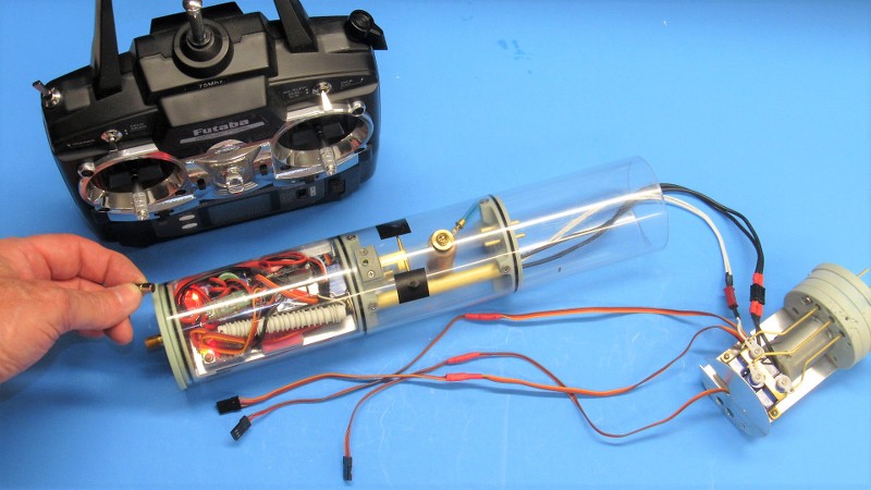
        Most r/c submarine transmitters are configured like aircraft as to specific stick and switch function, what is called, 'mode 2'.

        Typical r/c submarine transmitter controls go like this: The two-axis stick on the right hand side of the transmitter: Bow planes, up(rise)/down(descend). Rudder, turn right/left.

        The two-axis stick on the left hand side of the transmitter: Throttle up(ahead)/down(astern); ballast water, left(vent)/right(blow).

        The stern planes, in the special case of the HUNLEY model, controls the propeller thrust line about the pitch axis, counter-clockwise(rise)/clockwise(dive). Its the knob seen atop the right-hand side of the transmitter case.

        This picture denotes the happy ending of a long, and sometimes frustrating process of getting the system organized, assembled, and working in some semblance of a coherent whole.


        I needed to extend the three servo leads to lengths that would not only interconnect the two dry spaces through the ballast tank conduit, but would also be of significant length to afford the slack required to pull both the forward device tray and after motor-bulkhead clear of the cylinder ends. Initially I simply soldered on extensions to the servo leads, but later found that the added thickness at the solder unions became an interference issue within the conduit. Rather late in the game I was forced to abandoned the soldered extensions and substitute three-wire servo leads of appropriate length from a bulk spool I had at hand. The soldered unions in this case occurred back in the after dry space, well clear of the tight confines of the conduit.

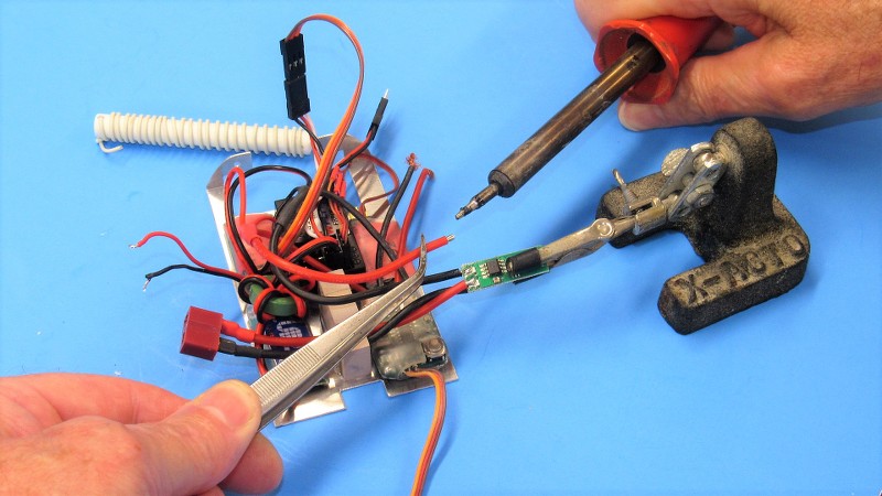
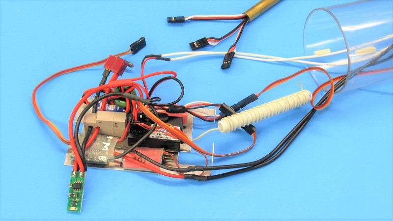
        The ch-4 output from the receiver controls the ballast sub-system servo and LPB electronic switch (2IS). As power and signal is shared between the two devices I soldered together a Y-connector to control the two devices from one input, that work underway on the left side of the photo.

        The two heavy wire pairs below are for the LPB (white wires) and motor (black wires). These pairs, along with the three three-wire servo leads, all eventually run from the forward dry space, through the ballast tank conduit, and into the after dry space.


        Soldering is straight forward using 60/40 (Lead/Tin) rosin core solder, a 25-Watt iron, and a non-acid liquid flux. Wires are first tinned, secured in some holding device, heat applied to adhere the wires together, and everything insulated and made nice and tidy (and, as it turned out with the three servo leads... too damn bulky to fit the conduit!) with heat-shrink tubing. I should have staggered the length of each wire of a three-wire lead. But... nnooooo! I piled each splice atop the other like a moron. Lesson learned!


        I made use of the excellent little KME magnetic mission-switch. This device permits on/off operation of the system by the simple wave of a magnet over the switches sensor. This type switch eliminates the need for the bulk and complexity of a typical toggle-switch outfitted with a watertight boot. Here I'm wiring it up the magnetic switch to the system.


        Not many are into the r/c vehicle game as deeply as me, but years ago I found that by shelling out the money for a proper crimping tool and sets of crimp-on connectors specifically designed for the type-J connectors (favored by all modern makers of r/c equipment) a great deal of time, and space within the tight confines of a WTC could be saved by making up my own leads and/or shortening existing ones.

        Here I'm demonstrating how the process works. A big advantage to the type-J connector is that the crimped in place pins can be removed from the plastic body easily -- without damage, to permit running of the (typically three) lead wires through the tight confines of a conduit -- and re-assembling once on the side of the conduit.

        Note how I've secured the KME mission-switch atop the RenShape foundation with two loops of sail-twin. Sometimes the old stuff is the best stuff.

        That green painted Iron doughnut is an inductive spike smoother-outer. Overkill for this job and the damned thing took up too much real-estate -- had to go! I get an unwanted DC pulsing from the battery eliminator circuit by doing that, but today's receives are smart enough to filter that minor fluctuation out at the front end and process the pulse-train just fine.


        The KME magnetic switch will eventually be mounted atop that brown, RenShape plastic foundation glued to the forward end of the device tray. This places the sensor close to the top of the WTC's cylinder so that there will be a short distance between it and the activating/deactivating magnet that will be swept by the WTC to turn things on and off. That foundation is also a strain-relief block for the cables that run to the battery-system Deans connector.

        I've already run the LPB and motor power wires through the WTC's conduit. And everything has been wired up and connected except for the three servo leads.


        Before cramming the three servo leads into the already tight conduit I did a complete systems test. I've just turned the system on with a magnet and will fiddle all the sticks and knob to make sure everything works as advertised. Note that I have yet to mount the mission-switch or remove the BEC's choke doughnut. This initial systems test a preliminary -- you don't want to get too far ahead of your skies: if there is going to be an issue make that issue apparent because of one or two steps taken since the last test, not a whole series of operations since the last test. Make trouble-shooting a whole lot easier if you can keep the number of suspects to a minimum during fault identification. In the Navy we called it, 'Easter egging'.

        https://imagizer.imageshack.com/v2/800x600q90/923/zJK50h.jpg[/IMG]

        AND THAT, SPORTS FANS, IS WHERE EVERTHING WENT SOUTH!!!!

        I mounted the tray into the forward dry space, and started to route the servo wires through the conduit. NO GO! Those fat splice points along the length of the leads would jam within the conduit. And that's what made me chop these leads off close to the servos and graft on three lengths of virgin lead from my stash of three-wire lead. That took an evening, but I was then able to fit the three leads into the conduit!

        A final dry run-up of the installed and buttoned up system and... amazingly... it all worked. Hell yeah! Suck it, Murphy!


        First practical test, an important one, is to check for leaks. At either end is mounted a tire-valve (Schrader-valve) on a bulkhead.

        When you push home the last of the two end bulkheads, it creates a slight over-pressure within the cylinder. That over-pressure is dumped by depressing the Schrader-valve stem momentarily to get the interior of the WTC equal to that of atmospheric pressure.

        To leak-test the WTC I remove the core-valve from the valve body and press-fit a length of flexible hose. Submerging the WTC underwater and blowing on the hose (while doing so, firmly holding the two outboard bulkheads on tight so they don't pop off) will cause any leakage points to bubble and reveal the exact point of leaking. In this case, the WTC passed this test the first time. The hose removed and the core of the Schrader-valve re-installed (only an idiot would forget to put the core back in before the next in-water test... guess who!).

        Who is John Galt?

        Comment

        • trout
          Admiral
          • Jul 2011
          • 3545

          "only an idiot would forget to put the core back in before the next in-water test" I fall into that category......been there, done that - earned the badge. The unfortunate part is I seem to find new ways to mess up!
          If you can cut, drill, saw, hit things and swear a lot, you're well on the way to building a working model sub.

          Comment

          • He Who Shall Not Be Named
            Moderator
            • Aug 2008
            • 12253


            Mike Bratley, formerly a rag-hat bubble-head (he actually served as crew aboard one of the DSRV's in the day!) is today a high-ranking COD driver (you know, those uglier than sin, gray, turbo-prop flying mail-trucks used aboard Carriers). In his off-hours, which are few, he's a bit of a model-builder. He's into r/c boats, high-power rockets, and now r/c submarines.

            He dragged my sorry butt into his first r/c submarine project, a 1/72 Revell SKIPJACK. Not taking my advice to 'start slow' -- to keep the system components as basic as possible so he could learn and enjoy the many frustrations even a simple r/c submarine will present -- he completely ignored me and jumped into fancy lighting and autonomous control circuitry. What he needed me for was help with the fully retractable mast array!

            Holy-****! His first r/c submarine?!...

            Normally I dismiss this kind of thing as stupid-talk. But, he's almost finished with it, and from what I've seen, it's a rational, well thought out piece of work. Only hiccup is the means of translating the mast actuation servos unusually long travel from a motion that originates along the submarines longitudinal axis to a sharp 90-degree bend upward to push the masts up, and pull them down on command.

            At his place Mike handed me what appeared to be a length of stainless aircraft quality control cable (wonder where THAT came from?!), and sent me on my way after forcing me to eat steak and consume massive quantities of diet Mountain Dew. I told him I would work the problem back at the shop. And here are the gory details of what I came up with:

            So I came up with this mock-up of a three pulley mechanism to translate cable motion by 90-degrees. Nothing new here, airplanes have been doing this for over a hundred years.

            However, as the stainless steel cable was rather stout it experience a lot of internal stress and friction as the lay of the individual wires rubbed and twisted against each other as they negotiated the tight radius turn offered by the one-inch diameter main pulley. I know that Mike's servo can deliver the force to move the cable, but the weak link in his linkage is the magnets used to couple servo travel, within the SD, to outside travel, external of the SD. The experiment points to the need to find a more flexible cable material -- one that won't bind up when stressed like this. We're on the right track, but need to experiment with different type cabling.


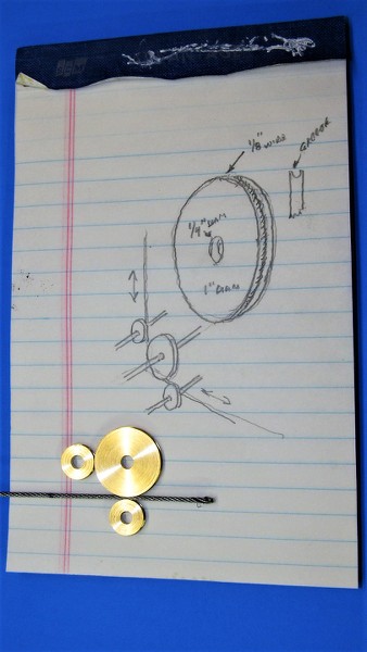
            Most hair-brained ideas are first sketched out to get a better feel of the mechanics involved. Here a isometric of the pulley arrangement is presented graphically. It's at this point in the design process that you identify the size limitations of the environment it will fit, which drives the size of the mechanisms components. I settled on the main pulls diameter being one-inch. That, along with the two smaller pulleys, and eventual frame that would support the pulleys, the entire mechanism would have to fit the narrow annular space between SD and the hulls inner surface.


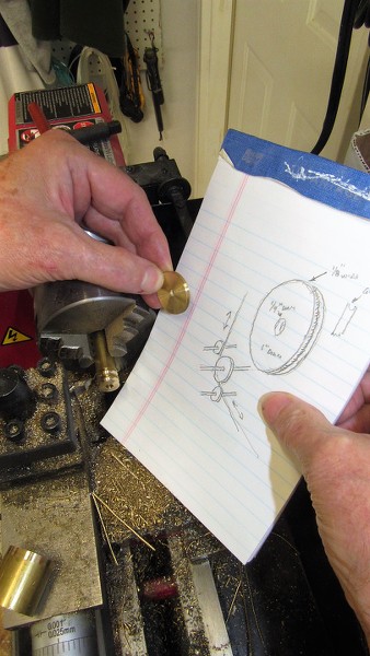
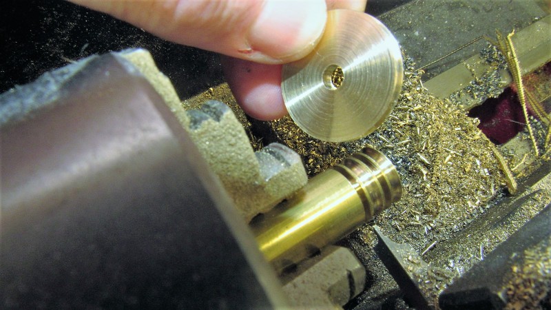
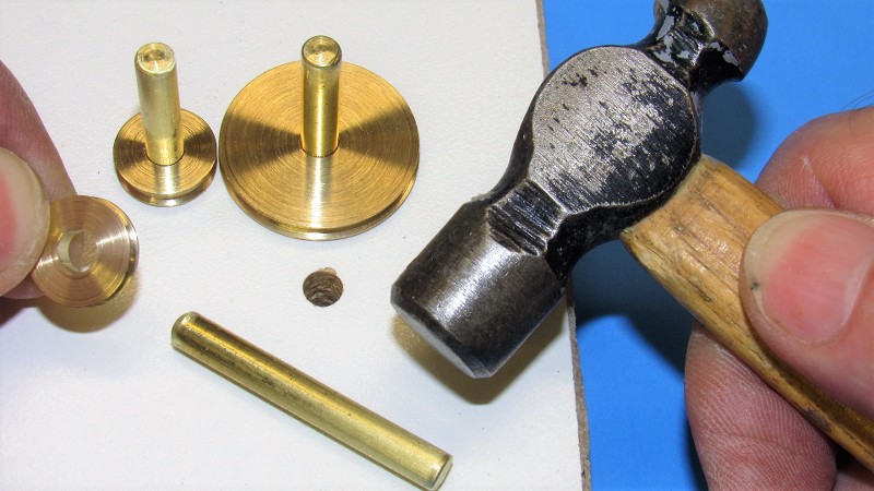
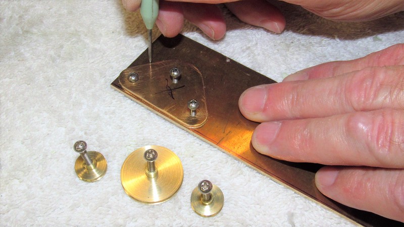
            A simple lathe job turning some machine-brass round-stock to size and shape. I've completed the main pulley and am just about finished with the two smaller ones, still chucked up and ready to be parted away.


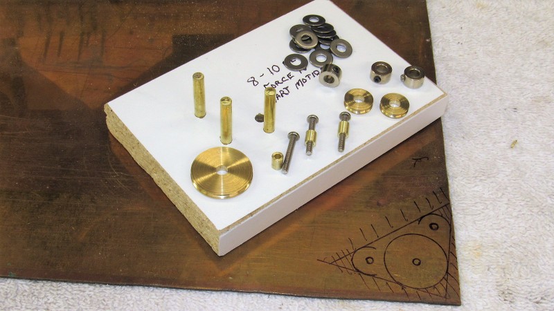
            Brass pins press-fit into holes drilled into some particle-board with a nice, clean white veneer. The pulleys rotated freely about these pins.


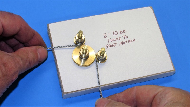
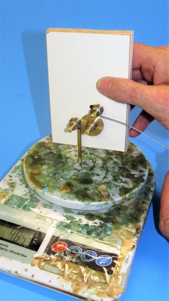
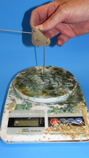
            The pulleys secured with wheel-collars, the cable reeved between the pulleys, and a determination of the force required to overcome the friction caused by the twisting wires within the lay of the cable.

            Ouch!

            Nearly a half-pound of force required to get the cable in motion. That won't do at all! We've got to come up with something of similar diameter, nearly as stout, but producing less internal friction when traveling over a tight radius pulley.


            Who is John Galt?

            Comment

            • redboat219
              Admiral
              • Dec 2008
              • 2735

              Originally posted by He Who Shall Not Be Named
              Mike Bratley, formerly a rag-hat bubble-head (he actually served as crew aboard one of the DSRV's in the day!) is today a high-ranking COD driver (you know, those uglier than sin, gray, turbo-prop flying mail-trucks used aboard Carriers). In his off-hours, which are few, he's a bit of a model-builder. He's into r/c boats, high-power rockets, and now r/c submarines.

              He dragged my sorry butt into his first r/c submarine project, a 1/72 Revell SKIPJACK. Not taking my advice to 'start slow' -- to keep the system components as basic as possible so he could learn and enjoy the many frustrations even a simple r/c submarine will present -- he completely ignored me and jumped into fancy lighting and autonomous control circuitry. What he needed me for was help with the fully retractable mast array!

              Holy-****! His first r/c submarine?!...

              Normally I dismiss this kind of thing as stupid-talk. But, he's almost finished with it, and from what I've seen, it's a rational, well thought out piece of work. Only hiccup is the means of translating the mast actuation servos unusually long travel from a motion that originates along the submarines longitudinal axis to a sharp 90-degree bend upward to push the masts up, and pull them down on command.

              At his place Mike handed me what appeared to be a length of stainless aircraft quality control cable (wonder where THAT came from?!), and sent me on my way after forcing me to eat steak and consume massive quantities of diet Mountain Dew. I told him I would work the problem back at the shop. And here are the gory details of what I came up with:

              So I came up with this mock-up of a three pulley mechanism to translate cable motion by 90-degrees. Nothing new here, airplanes have been doing this for over a hundred years.

              However, as the stainless steel cable was rather stout it experience a lot of internal stress and friction as the lay of the individual wires rubbed and twisted against each other as they negotiated the tight radius turn offered by the one-inch diameter main pulley. I know that Mike's servo can deliver the force to move the cable, but the weak link in his linkage is the magnets used to couple servo travel, within the SD, to outside travel, external of the SD. The experiment points to the need to find a more flexible cable material -- one that won't bind up when stressed like this. We're on the right track, but need to experiment with different type cabling.


              Most hair-brained ideas are first sketched out to get a better feel of the mechanics involved. Here a isometric of the pulley arrangement is presented graphically. It's at this point in the design process that you identify the size limitations of the environment it will fit, which drives the size of the mechanisms components. I settled on the main pulls diameter being one-inch. That, along with the two smaller pulleys, and eventual frame that would support the pulleys, the entire mechanism would have to fit the narrow annular space between SD and the hulls inner surface.


              A simple lathe job turning some machine-brass round-stock to size and shape. I've completed the main pulley and am just about finished with the two smaller ones, still chucked up and ready to be parted away.


              Brass pins press-fit into holes drilled into some particle-board with a nice, clean white veneer. The pulleys rotated freely about these pins.


              The pulleys secured with wheel-collars, the cable reeved between the pulleys, and a determination of the force required to overcome the friction caused by the twisting wires within the lay of the cable.

              Ouch!

              Nearly a half-pound of force required to get the cable in motion. That won't do at all! We've got to come up with something of similar diameter, nearly as stout, but producing less internal friction when traveling over a tight radius pulley.

              How about bicycle cables?
              Make it simple, make strong, make it work!

              Comment

              • He Who Shall Not Be Named
                Moderator
                • Aug 2008
                • 12253

                Maybe......
                Who is John Galt?

                Comment

                • redboat219
                  Admiral
                  • Dec 2008
                  • 2735

                  Dan Kachur's Skipjack periscope mechanism.
                   
                  Make it simple, make strong, make it work!

                  Comment

                  • He Who Shall Not Be Named
                    Moderator
                    • Aug 2008
                    • 12253


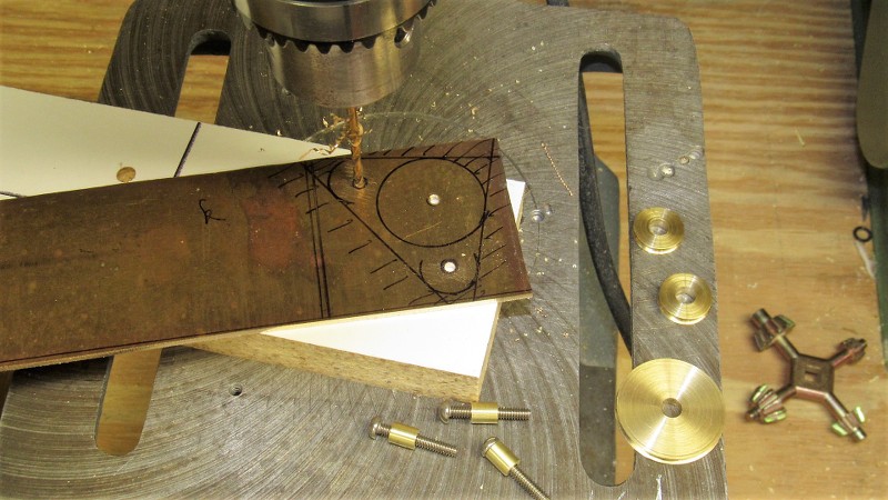
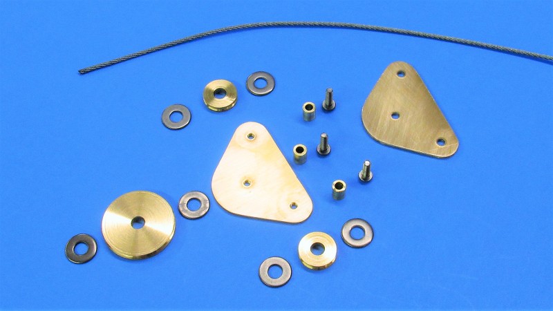
                    Today I went from mock-up to practical three-pulley fairlead. I was delighted to find that the drag of the mechanism went down to only five-ounces. Not bad. I think Mike can work with that.


                    Who is John Galt?

                    Comment

                    • Das Boot
                      Rear Admiral
                      • Dec 2019
                      • 1149

                      We aren’t worthy.
                      Of the 40,000 men who served on German submarines, 30,000 never returned.”

                      Comment

                      • redboat219
                        Admiral
                        • Dec 2008
                        • 2735

                        Wouldn't a brass tube with an internal diameter slightly bigger than the wire and bent 90 degrees work as a guide?
                        Last edited by redboat219; 10-29-2021, 07:38 AM.
                        Make it simple, make strong, make it work!

                        Comment

                        • mike27283
                          Lieutenant, Junior Grade
                          • Aug 2020
                          • 18

                          My first post...at the 'gentle' insistence of my friend and mentor - 'He Who Shall Not be Named'. I am now moving from site 'stalker' (for many years) to an actual poster.

                          - Many many thanks to David for his lessons, humor and occasional kick in the pants - as well as the flattering bio...
                          - Thanks to Trout for the running light housings and Bob for his advice, drive, and vision for this unique hobby.
                          - My work pales in comparison to those on this site and I greatly appreciate the talent I have seen here which I am inadequately trying to emulate.

                          redboat219 - I started with a throttle cable linkage, moved onto brass tube (of too small a diameter) and in the midst of trying to figure out how to waterproof the giant hole leading out of the WTC from the linear servo cable linkage lost the 'forest for the trees' ... It was David's genius idea to create the magnetic shuttle which solved the 'hole' problem. In the attached pictures I have now used larger brass tubing successfully to house the magnets as well as route the linkage cable - especially now that I have some decent tube benders from Harbor Freight. The rollers are part of the lesson plan teaching me how to craft metal parts - and they do significantly reduce friction. The plan is to mount the assembly (once complete) to the underside of the upper hull half - therefore eliminating the need to somehow manually hook up the mechanism to the mast raising platform. The only manual connection will be the magnet linkage to drive the fairwaters.

                          Hopefully the images and videos upload here properly...but am including to briefly show the magnet shuttle in current state as well as some of the build history. My motivation is several fold - I am a former Submariner ('85-'95...SSBN 728, TTF, and DSU - Seacliff (DSV-4) and rode the Mystic (DSRV), my father was a plank owner on the USS Scorpion (the pic of the coffee cup used to be his), I love the challenge - and RC subs are just damn cool!

                          The mast assembly has antennas that raise within the fairings, the sub is lighted to include a submarine ID beacon that flashes at the correct rate - torpedo's are on the menu at some point - creating a working accurate scale model is my goal. I've even considered some kind of alka-seltzer tablets to eject as counter measures... All of this is of course is against the best advice in the hobby - start slow.

                          The sub ID beacon is what led me initially down the road to incorporate a Parallax BS2 Basic Stamp microcontroller into the build. The BS2 controls the beacon, monitors for a PW loss and if detected flashes the masthead light at a fast rate as a visual indication when the sub pops to the surface after the BLM blows the reserved air charge - I also incorporated a leak detect function. If a leak is detected the sub will blow to the surface and flash both the sub ID beacon and the masthead light at a fast rate. I also incorporated a magnetic relay which signals the BS2 to turn off the ID beacon and Masthead light when the masts are in the down position. The running lights and stern light always stay illuminated as a visual indication the sub is powered.

                          Go Navy!


                          - Having issues uploading photos...hopefully the videos are accessible here on the post. I'll add photos later once I get it figured out...

                          Comment

                          • trout
                            Admiral
                            • Jul 2011
                            • 3545

                            Wow, that is really amazing!
                            If you can cut, drill, saw, hit things and swear a lot, you're well on the way to building a working model sub.

                            Comment

                            • redboat219
                              Admiral
                              • Dec 2008
                              • 2735

                              Mike, the brass tube I was proposing was only just a short section enough to coax the wire to bend 90°. The other end would terminate with a rare earth magnet that can engage with a corresponding one on the output shaft of say a 3" SD. Click image for larger version

Name:	Notes_211031_153318.jpg
Views:	275
Size:	53.4 KB
ID:	155196
                              Make it simple, make strong, make it work!

                              Comment

                              • mike27283
                                Lieutenant, Junior Grade
                                • Aug 2020
                                • 18

                                My god...had to convert all of my HEIC files to JPEG...as well as resize - what a hassle. Anyways - initial learning curve surmounted ... Magnetic shuttle pics listed and video. redboat219 - yes - totally onboard. You can see in the photo there are 2 - 90° turns leading to the top of the WTC as you depict. Once I have the roller potion David created (and used as a teaching aid) installed I'll post some new photos. I assume this design could be used for other applications.

                                Here is a video of it in operation: https://youtu.be/NnLz8u96Tco

                                Attached Files

                                Comment

                                Working...