Welcome to our forums. For the best in R/C submarine kits, components and accessories, be sure to visit the Nautilus Drydocks
If this is your first visit, be sure to
check out the FAQ by clicking the
link above. You may have to register
before you can post: click the register link above to proceed. To start viewing messages,
select the forum that you want to visit from the selection below.
I have been looking at your endcap manufacture with a lot of interest, and I have a questions.
Who is your supplier of bushings, and gears for your shafts ?
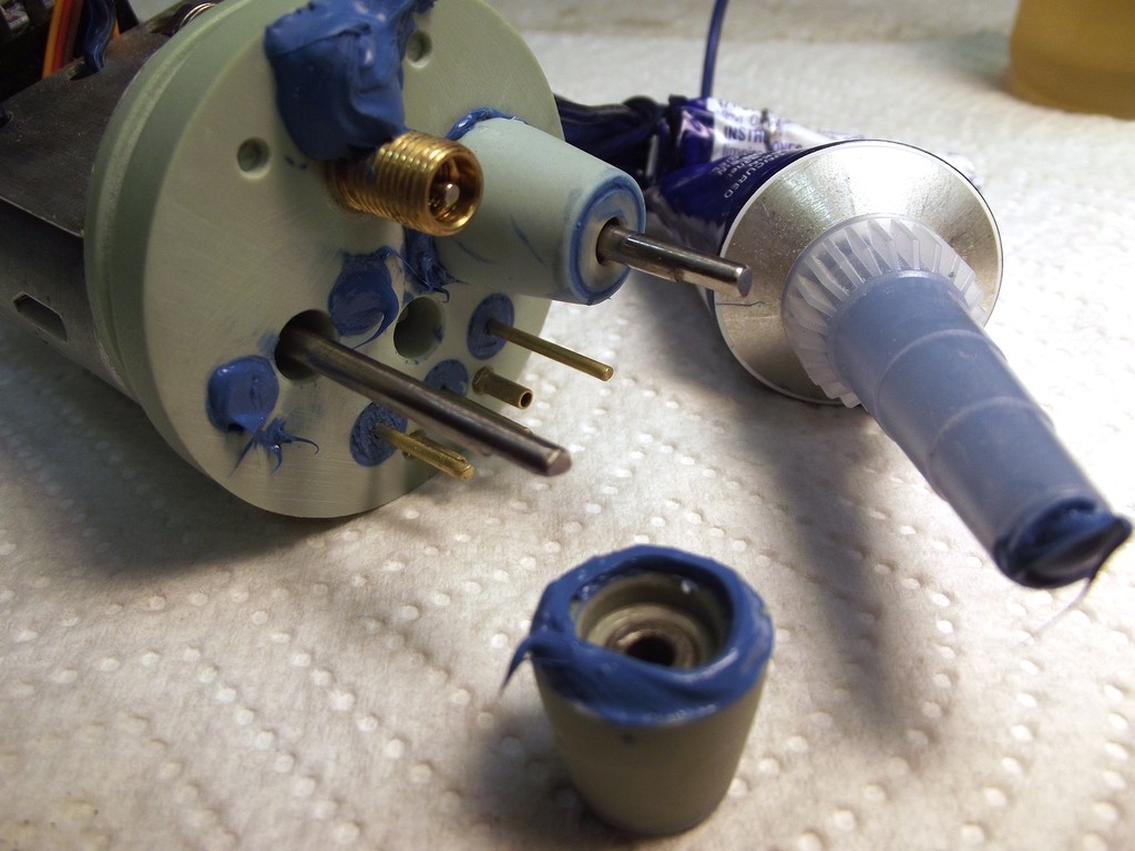
With the twin shafts off the one motor do you have any pics of how the shafts are sealed?
I have been looking at your endcap manufacture with a lot of interest, and I have a questions.
Who is your supplier of bushings, and gears for your shafts ?
With the twin shafts off the one motor do you have any pics of how the shafts are sealed?
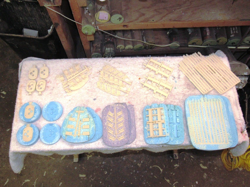
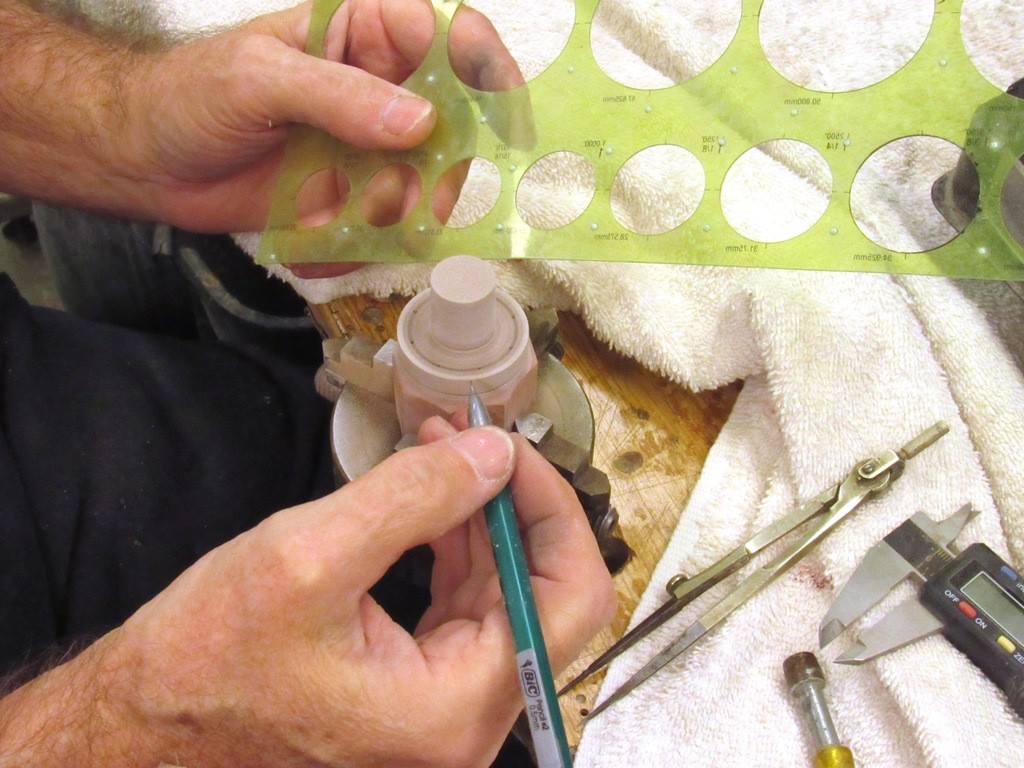
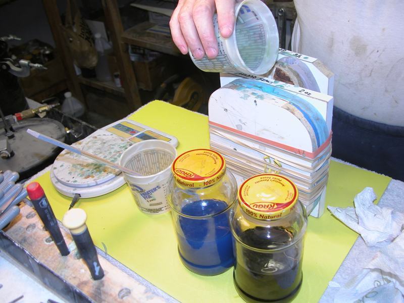
I rely heavily on reproducible model building techniques. My principle one is resin casting. Most of that work, as illustrated here, is simple pressure assisted casting. Some hum-drum piece work needed to make the parts utilized by the r/c submarine modular systems I market through the Nautilus Drydocks. Polyurethane casting resin is catalyzed, poured into rubber tools, pressurized till it hardens, then the tools are opened and the cast parts extracted, and the process repeated.
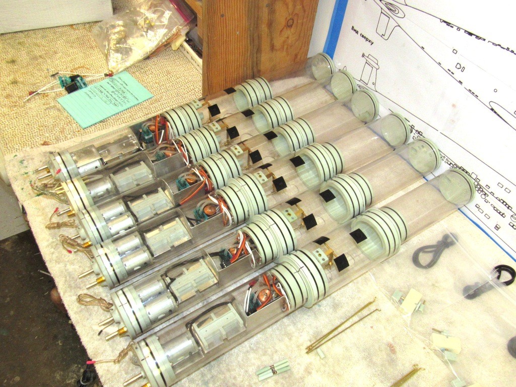
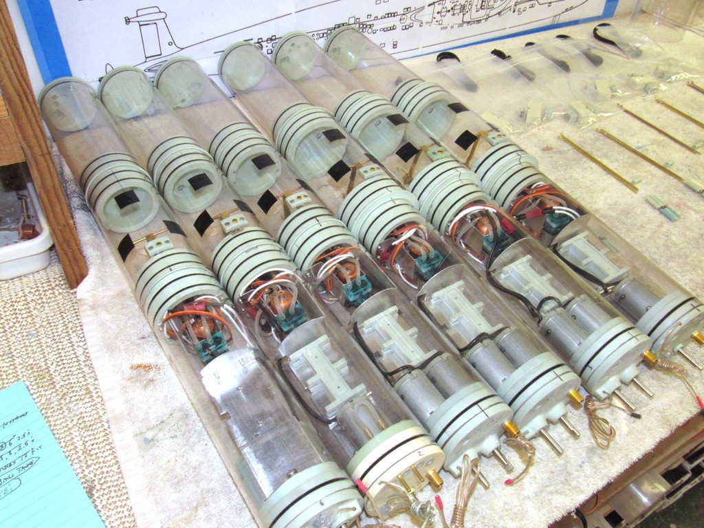
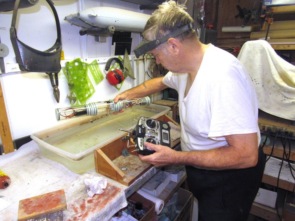
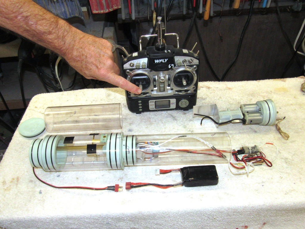
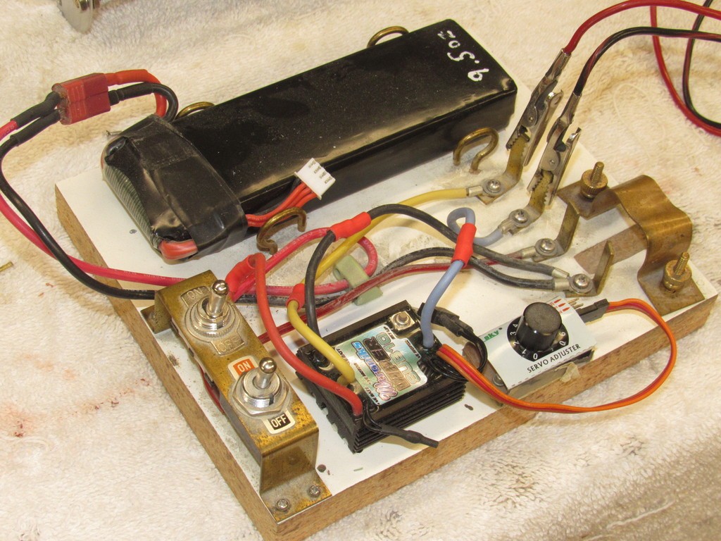
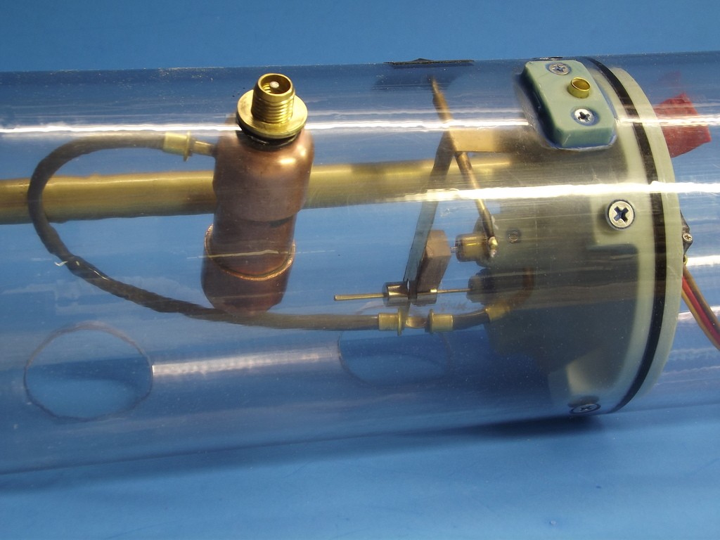
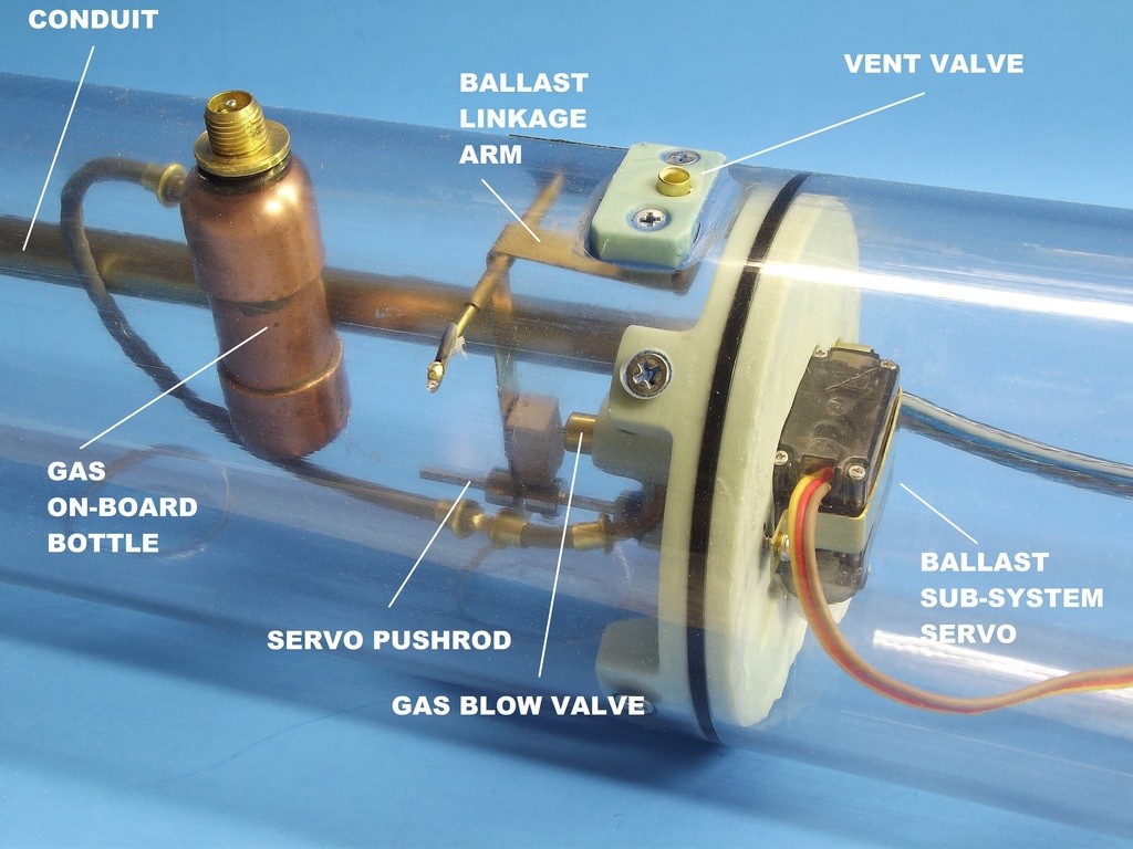
Spent most of last week leak checking and certifying a group of our major project, the SubDriver. This is a watertight enclosure containing the propulsion, control, and ballast sub-systems needed to operate an r/c model submarine. These things are our bread-and-butter. We used to do industrial displays, movie effects miniatures, private commissions, and resin kits (remember Lunar Models?). Today we support the r/c submarine hobby trade.
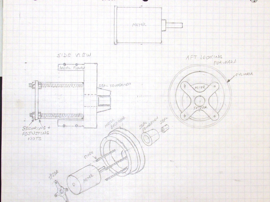
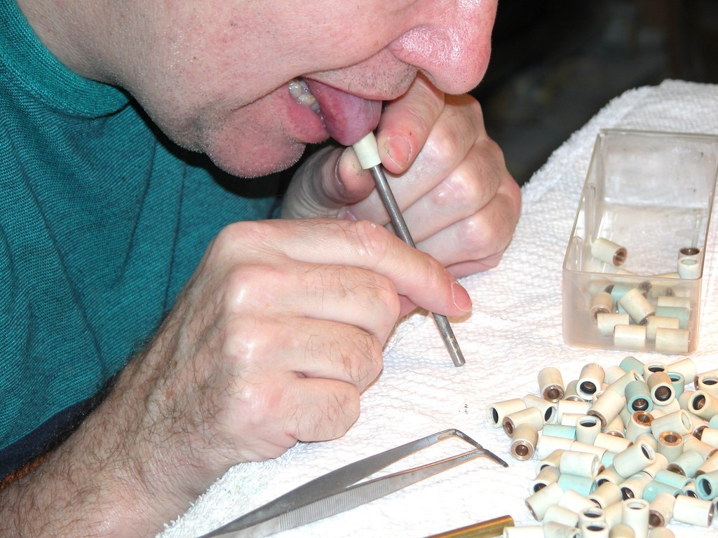
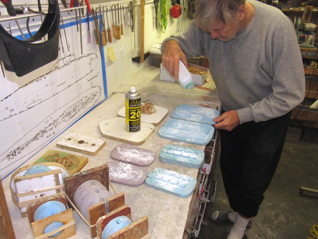
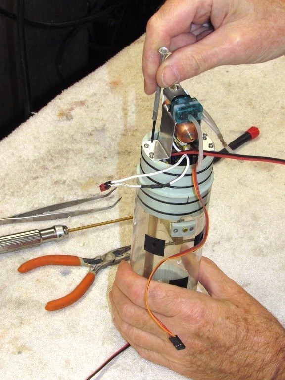
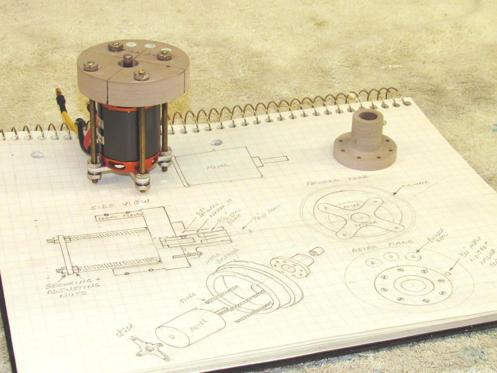
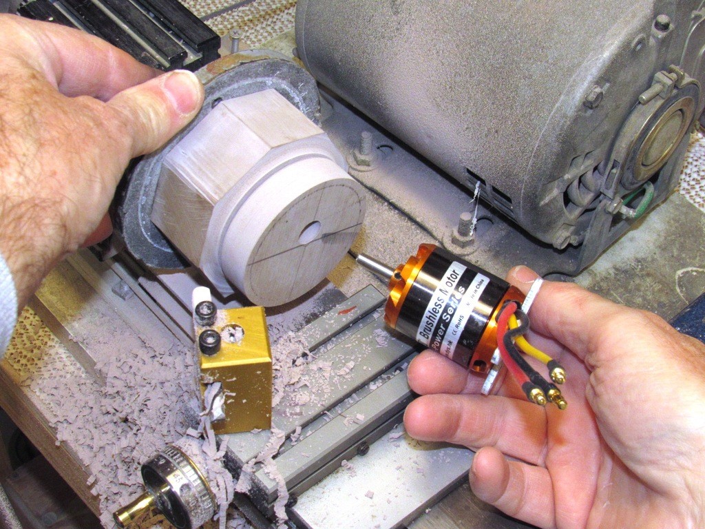
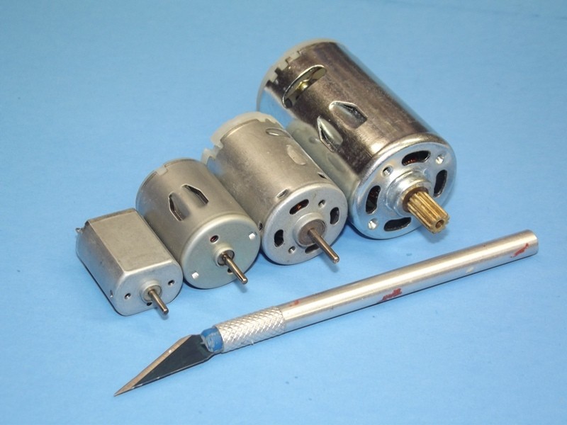
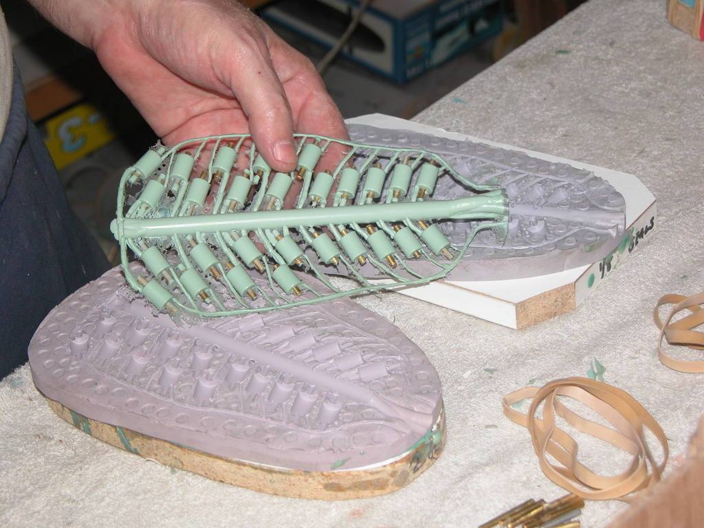
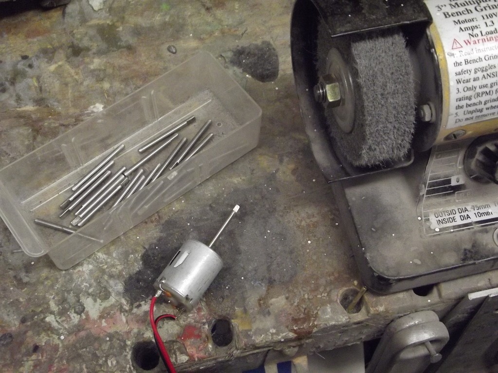
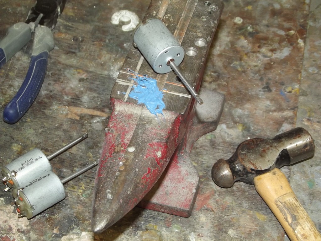
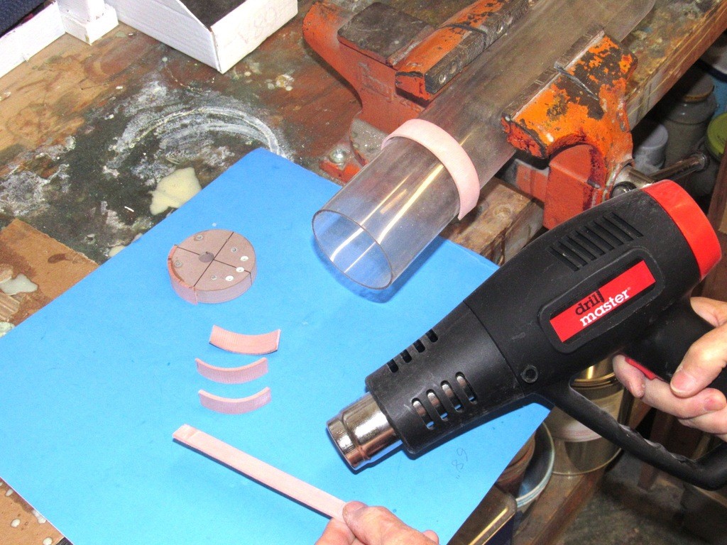
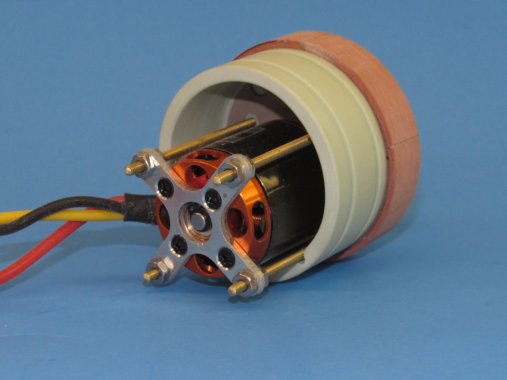
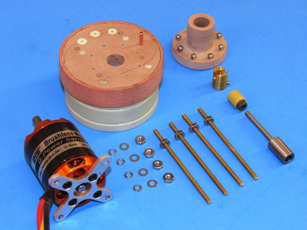
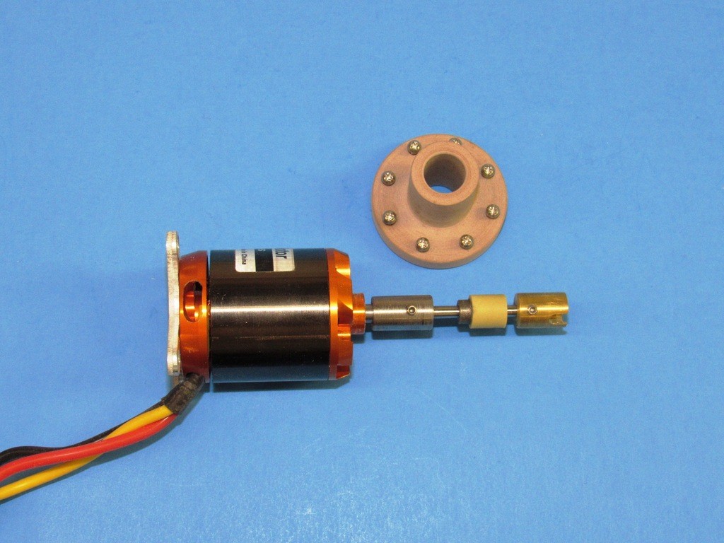
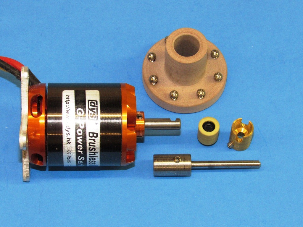
I'm in the process of joining the 21st Century: I'm switching from brushed to brushless motors. That has required some motor evaluation and development of new foundations to mount the motor(s) within the SubDriver. Here I'm mocking-up a motor-bulkhead master with motor and associated hardware. If it works in this form then it will work with the eventual cast resin pieces produced from the masters.
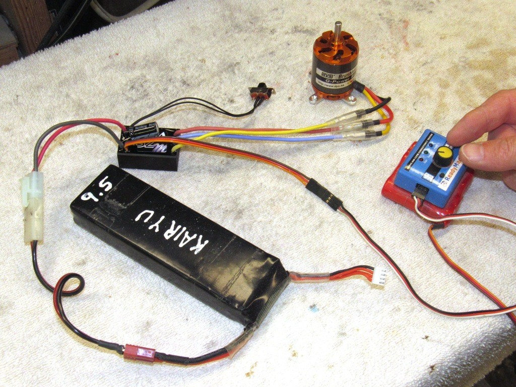
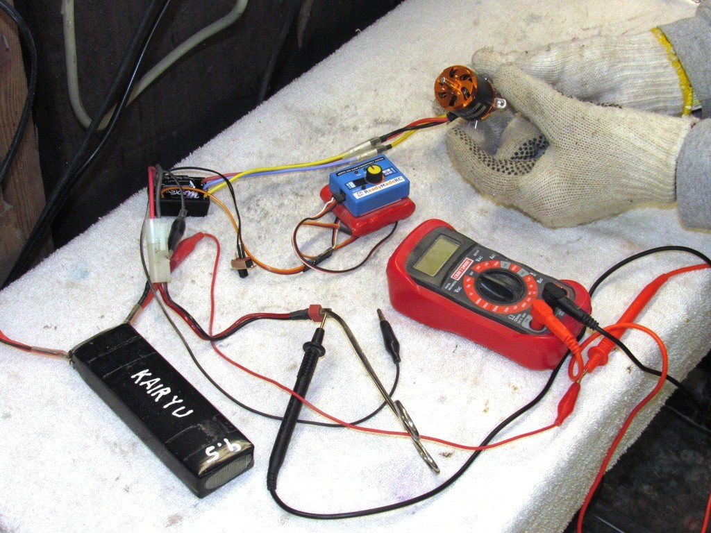
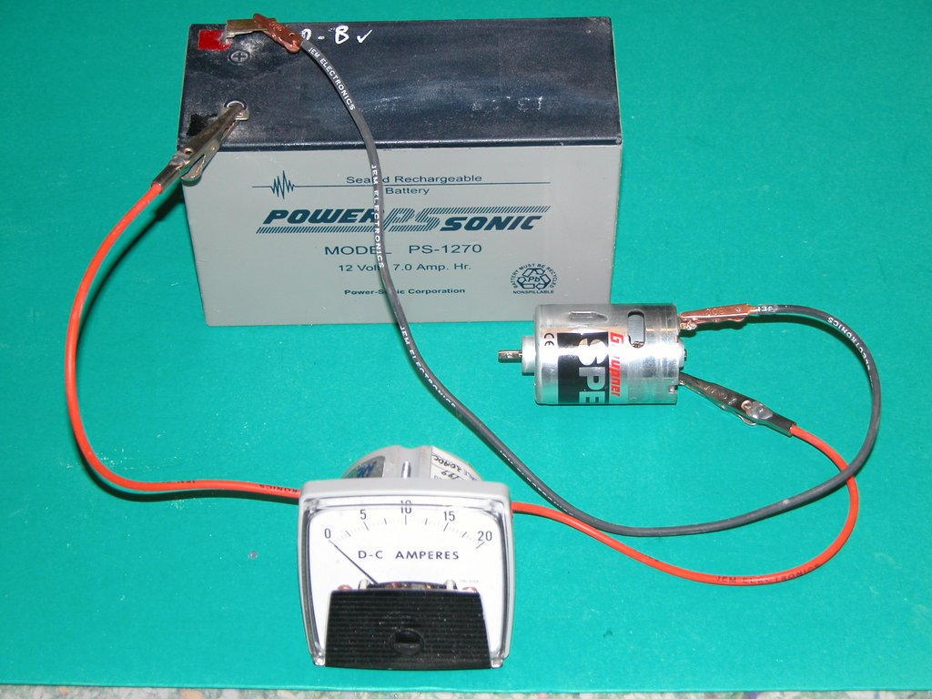
What are the gloves used for? Cold or testing the motor’s strength?
Yes, Tom. Testing the motors strength to stall, and observing maximum current draw -- need to know stuff like that before determining which ESC to use and rating of its protective fuse.
The same protocol I observed over thirty years ago when I selected brushed motors for my line of WTC's.
A wealth of great info once again. I do however have some more questions mainly to do with clarity of what I’m seeing.
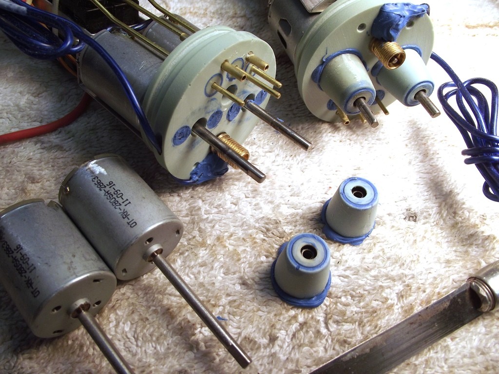
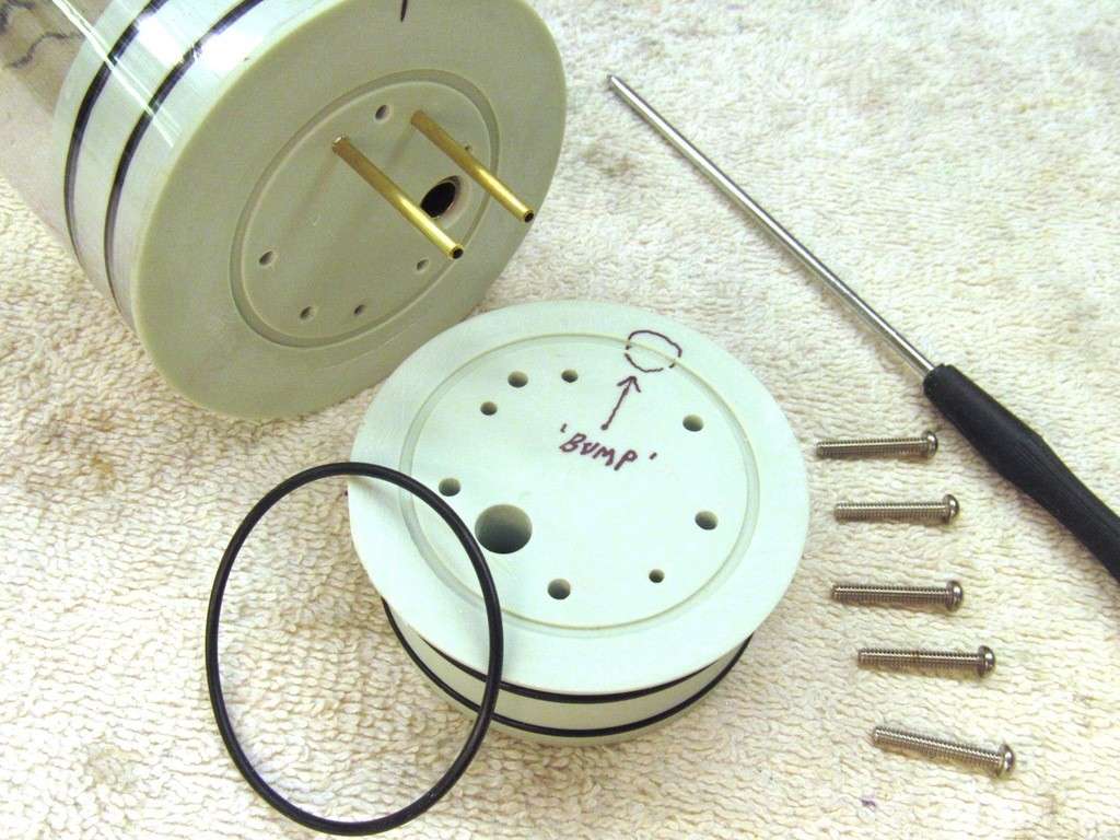
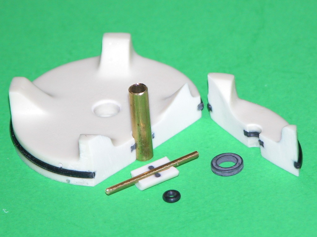
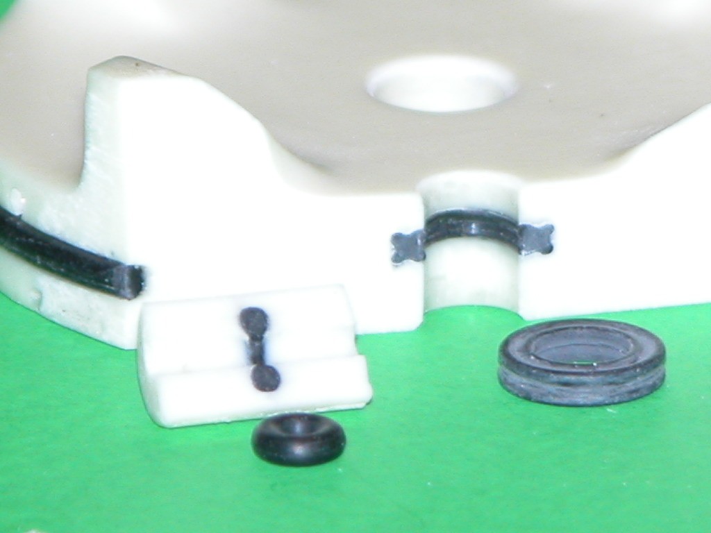
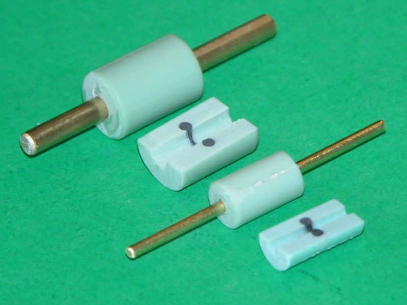
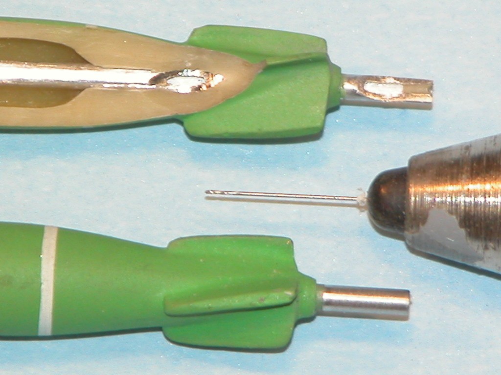
I notice on your end caps in the most recent pics where the pushrods are located, there is a faint ring of blue silicon around them. Are these inserts? I always assumed that your pushrod design simply meant sliding a tiny o ring on a brass shaft inside the silicon mould and the poly resin encased the o -ring after pulling out the brass core. Have I missed something here?
Also do you buy a length of stainless for your shafts, cut them to size and then drill the hole in the end to friction fit onto the shorter motor shaft? How do you guarantee that the new shaft extension is absolutely parallel with the original shaft or is any eccentricity taken by the flexing of other parts? I did read earlier that
Hello
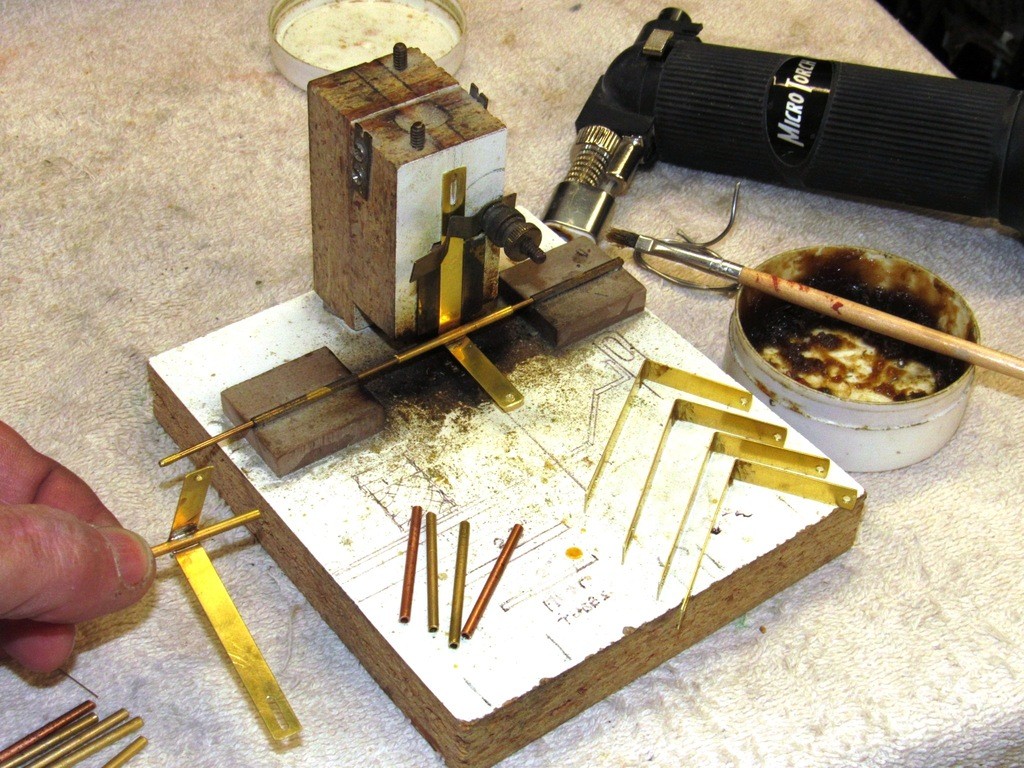
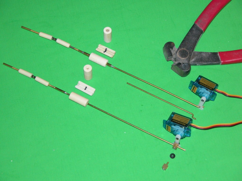
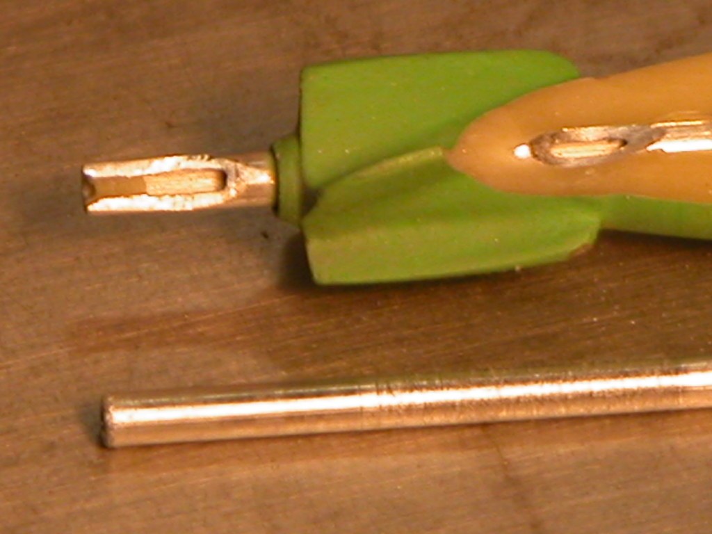
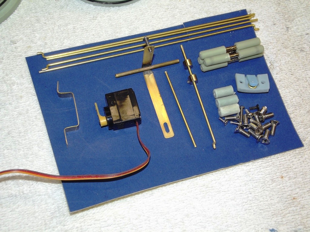
In your post 61 picture, what is that brass rod/bent strip for?
It's part of the ballast sub-system linkage -- it translates the push-pull of the servo push-rod to an up-down motion under the vent valve to open and close it. The picture shows the jig used to solder the pivot pin shaft to the L-shaped arm.
A wealth of great info once again. I do however have some more questions mainly to do with clarity of what I’m seeing.
I notice on your end caps in the most recent pics where the pushrods are located, there is a faint ring of blue silicon around them. Are these inserts? I always assumed that your pushrod design simply meant sliding a tiny o ring on a brass shaft inside the silicon mould and the poly resin encased the o -ring after pulling out the brass core. Have I missed something here?
Also do you buy a length of stainless for your shafts, cut them to size and then drill the hole in the end to friction fit onto the shorter motor shaft? How do you guarantee that the new shaft extension is absolutely parallel with the original shaft or is any eccentricity taken by the flexing of other parts? I did read earlier that
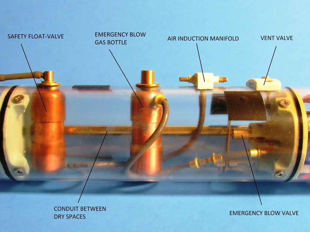
The only cast-in-place O-ring is the one that seals the end of the conduit that extends through the ballast tank and connects the forward to the after dry spaces within the SD. In this application I'll use either X or O-rings. No difference, just depends what I grab out of the bin.
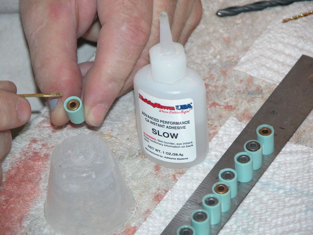
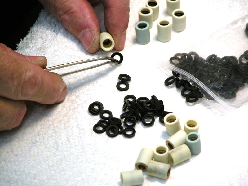
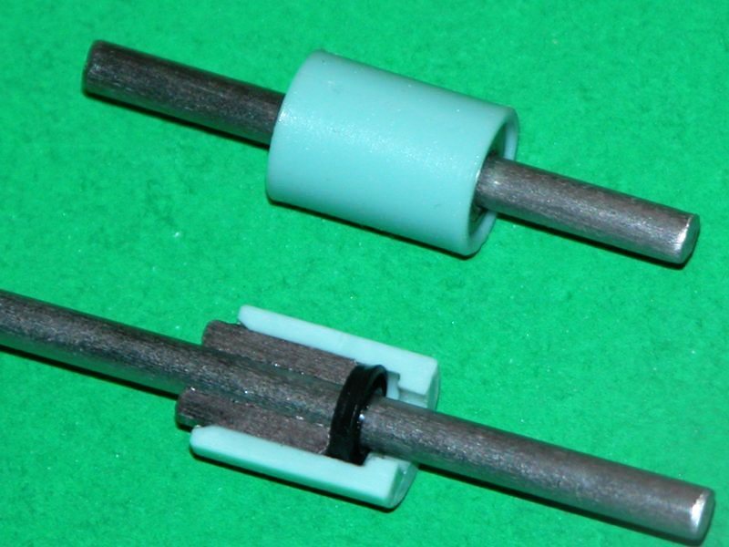
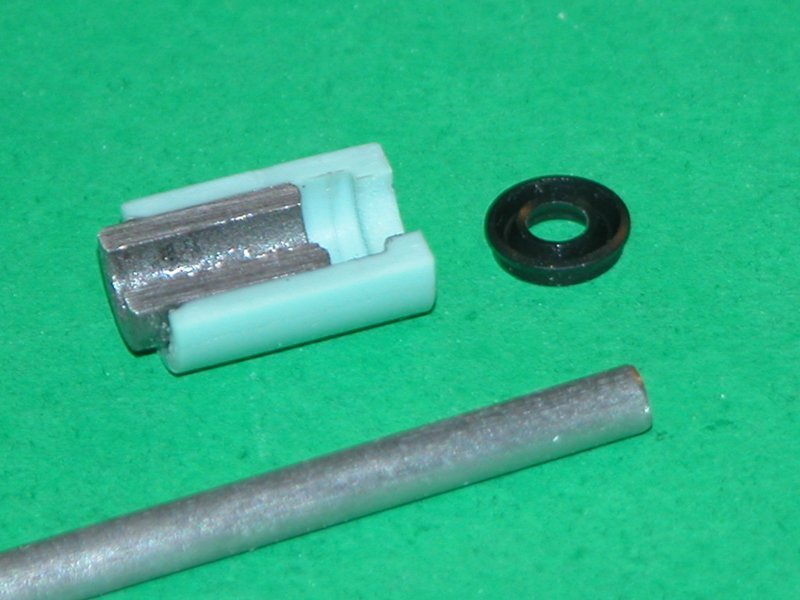
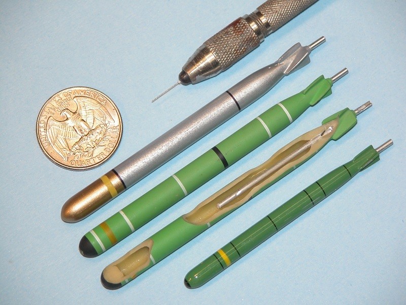
The pushrod and shaft seals are discrete items that are inserted and made watertight with silicon adhesive.
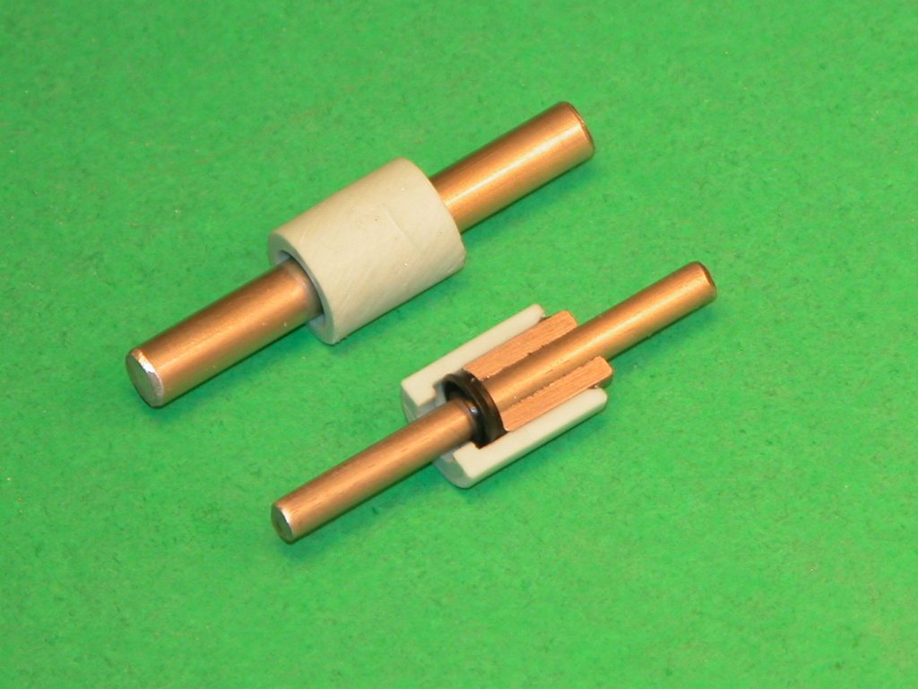
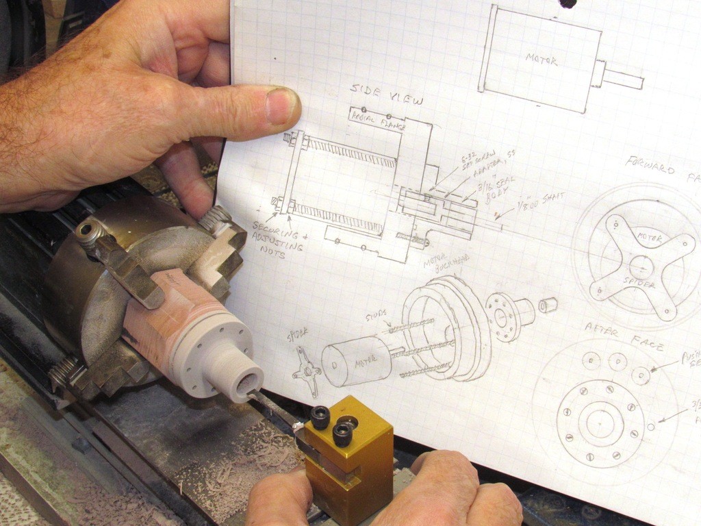
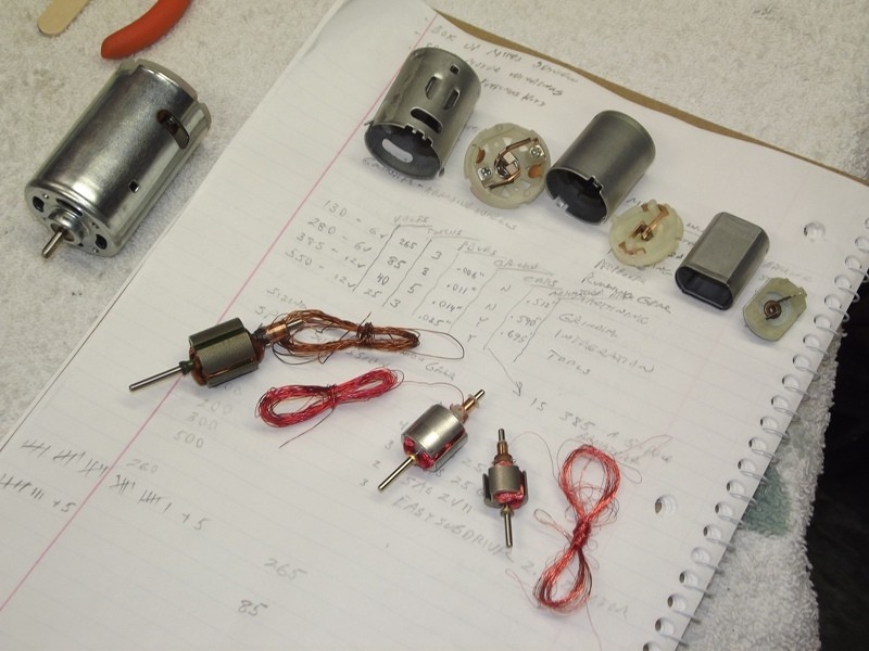
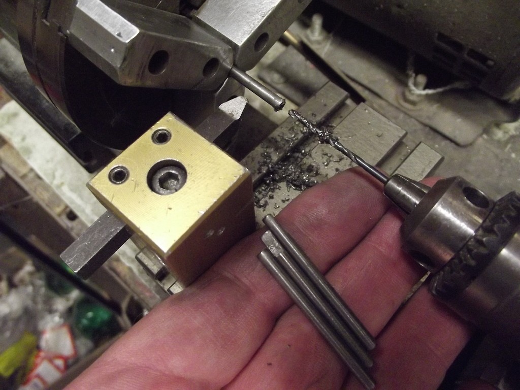
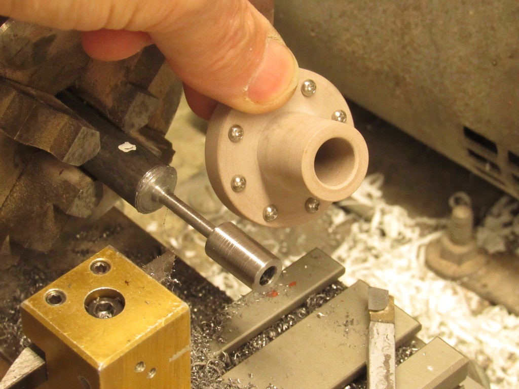
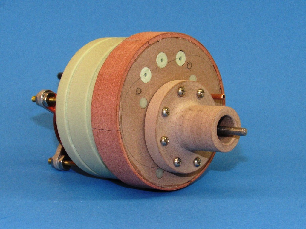
Shaft extensions are bored on the lathe. This insures exact centering of the hole to the shaft. I taper the motor shaft and make the fit between motor shaft and shaft extension a tight interference fit.
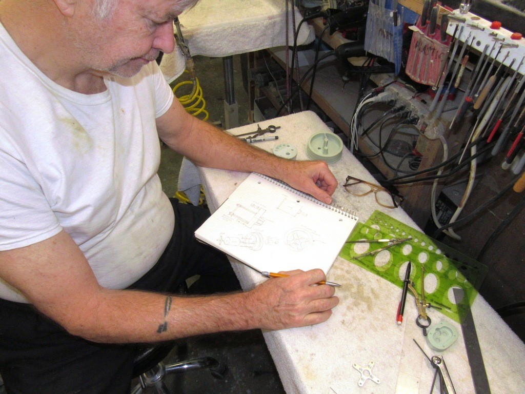
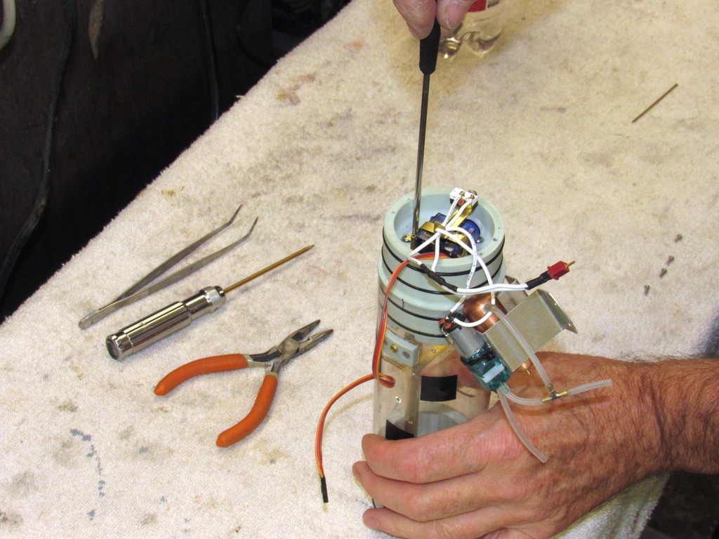
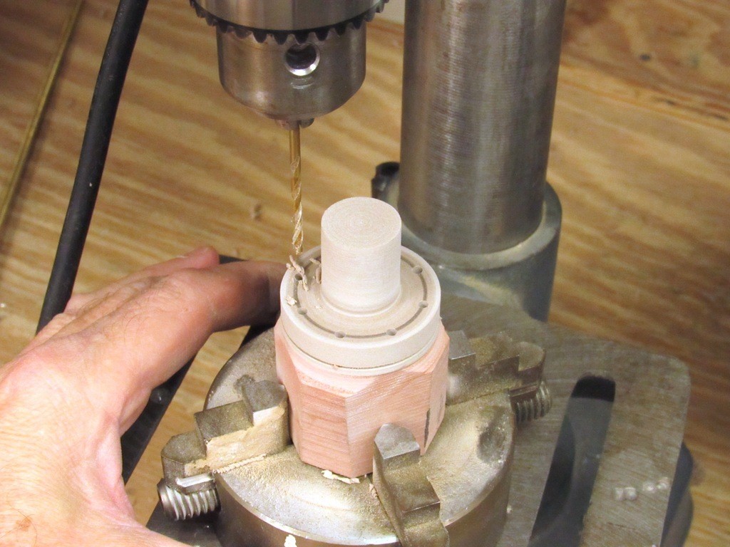
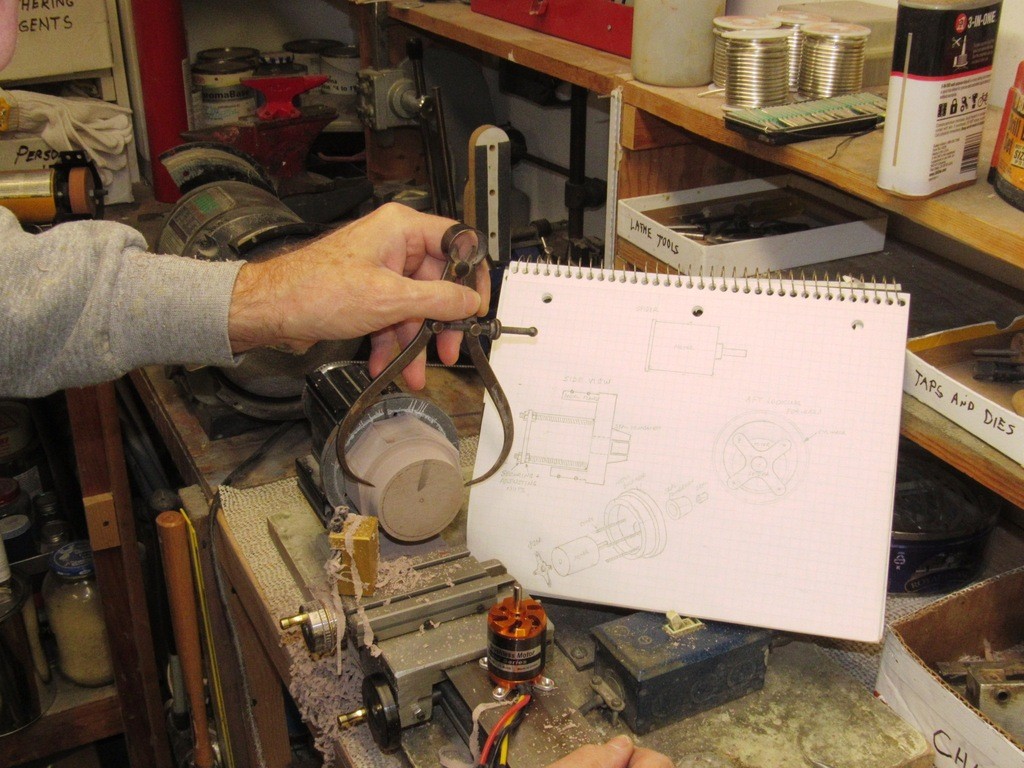
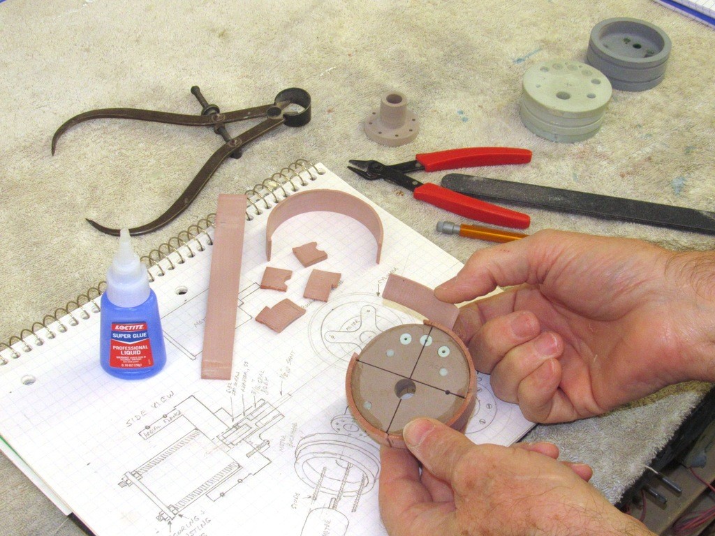
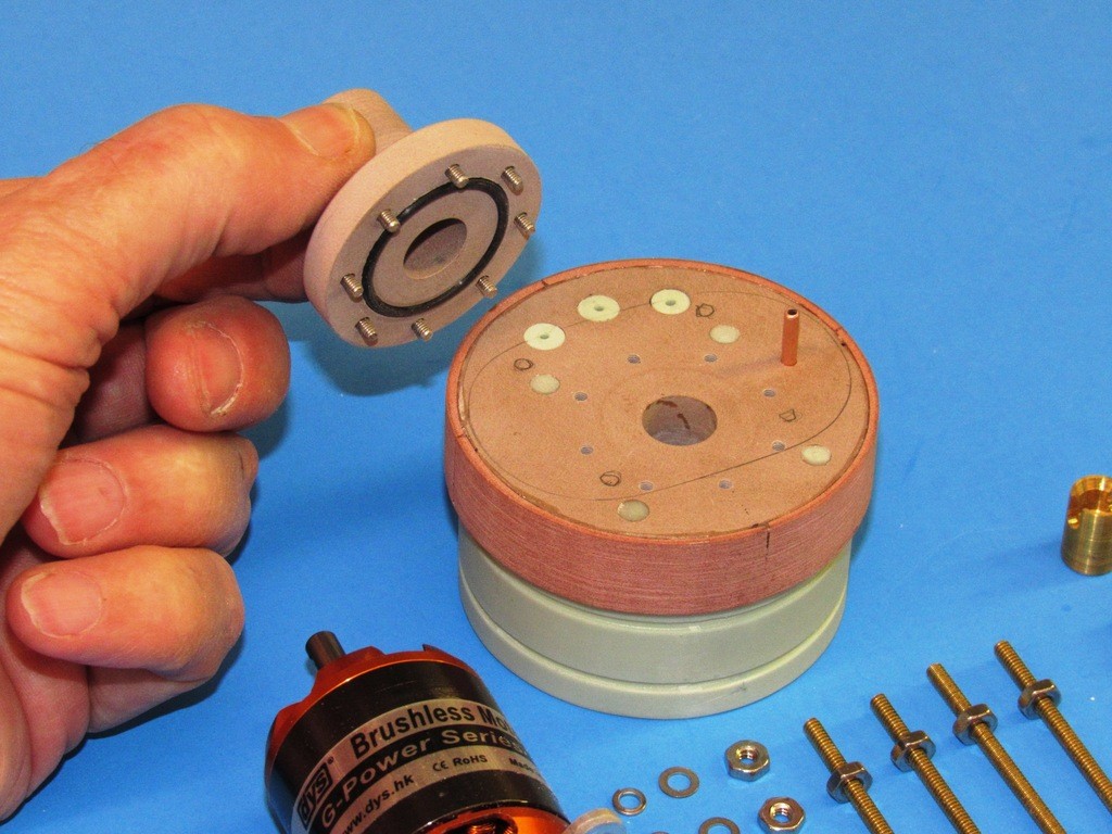
I've completed most of the grunt-work on the masters of a motor bulkhead that will mount a brushless propulsion motor for one of our SubDriver r/c submarine systems. I use the raw masters to check fit and operation in mock-up form. Once everything is working as planned (best laid plans … and all that happy horse-****), I refine the finish of the masters and turn them into rubber tooling from which production items will be cast.
Does that motor have a 5mm shaft going to 3/16" shaft?
Yes, the motor has a 5mm shaft. The shaft extension/adaptor in this case is 1/8", but I can make it any diameter I wish.
Bob had a good idea that would save a lot of MSD internal space: mount the motor in the wet! I'm working up a motor-bulkhead (MB) master for that arrangement today. Film at Eleven!

 Tweet
Tweet


Comment