
Dave you do any work today? Don't be slacking off you mess crank. I sanded down and primer painted the Yankee hull plug. Also shaped second to last hull section for the 1/72 670M, aka Charlie II. Work work work.
-
-
Sir question about how you poor your resign into the molds for your 1/32 torpedo. Do you just mix an poor into the canal and let gravity fill it OR do you high speed spin it in a machine OR do you use a syringe filled with resin and force it into the fill canal?
I use the Alumilite polyurethane casting resin. When mixed it has the viscosity of milk and easily fills a tool. With little trouble as long as the tool has adequate sprue, riser, and vent channeling to not only introduce the resin, but to provide a reservoir to account for crushed bubbles, and for the escape of displaced air from the tools cavities as the resin is introduced.
I pressurize the work while the liquid resin changes state to a solid, this crushes any bubbles in the mix or bubbles entrapped in the tools cavities. The make-up resin is provided by the riser cavity.
I've also spun-cast resin for special projects. But most of the time it's a simple gravity pour.
David
Last edited by He Who Shall Not Be Named; 12-16-2019, 07:51 PM.Comment
-
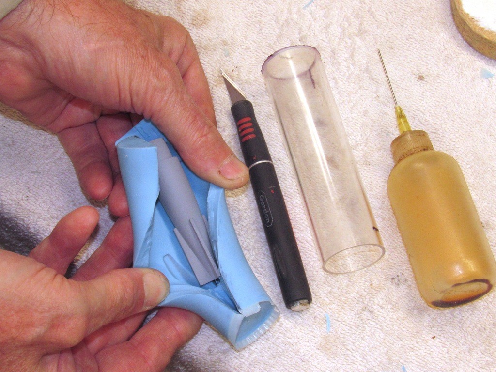
Thanks for All your time to answer us.Some more questions. Why did you go with the plastic tube as your container rather than a temporary made rectangular box with the mold then being two pieces? IS that aluminum rectangular strip with the squares and circles home made or bought? Last, in the picture with the tail piece being removed there is an oil bottle with a syringe needle,used in the process?
Thanks again Teacher Sir.Comment
-
Good observations, George.
I used discarded lengths of Lexan cylinder as the flasks (containment) for the rubber as their circular section insures a constant wall thickness around the circular masters. Any other geometry and it would be a waste of the very expensive RTV mold making rubber.
Those stainless steel scribing stencils are/were commercially available, the Verlinden company I believe. I bought those well over two decades ago. I do make my own acid-etched stencils, as well as parts on occasion


The oil is injected between the rubber and the inside wall of the flask to ease removal of the tool from the flask after casting the tool. Messy but effective. After that, insertion of the tool back into the flask is aided by lubricating the inside of the flask with talc.
DavidLast edited by He Who Shall Not Be Named; 12-17-2019, 01:15 AM.Who is John Galt?Comment
-
Hello, so you put oil on the rubber tool outside surface before inserting back into the lclear tube. What oil do you use?
Comment
-
Thank You for the lessons
Comment
-
SCRIBING This is the process of scraping (abrading) engraved, often narrow, depressions into the work. Most suited to representing seams between plates in close proximity to each other, such as access panels, hatch or door outlines, safety-track, missile hatches, even cheat-lines (waterlines, centerlines, datum lines, etc.), and breaks between fixed structure and control surfaces. In sheet-metal work scribing lines onto the sheet (blued to highlight the shiny engraved line) is a part of the layout process.
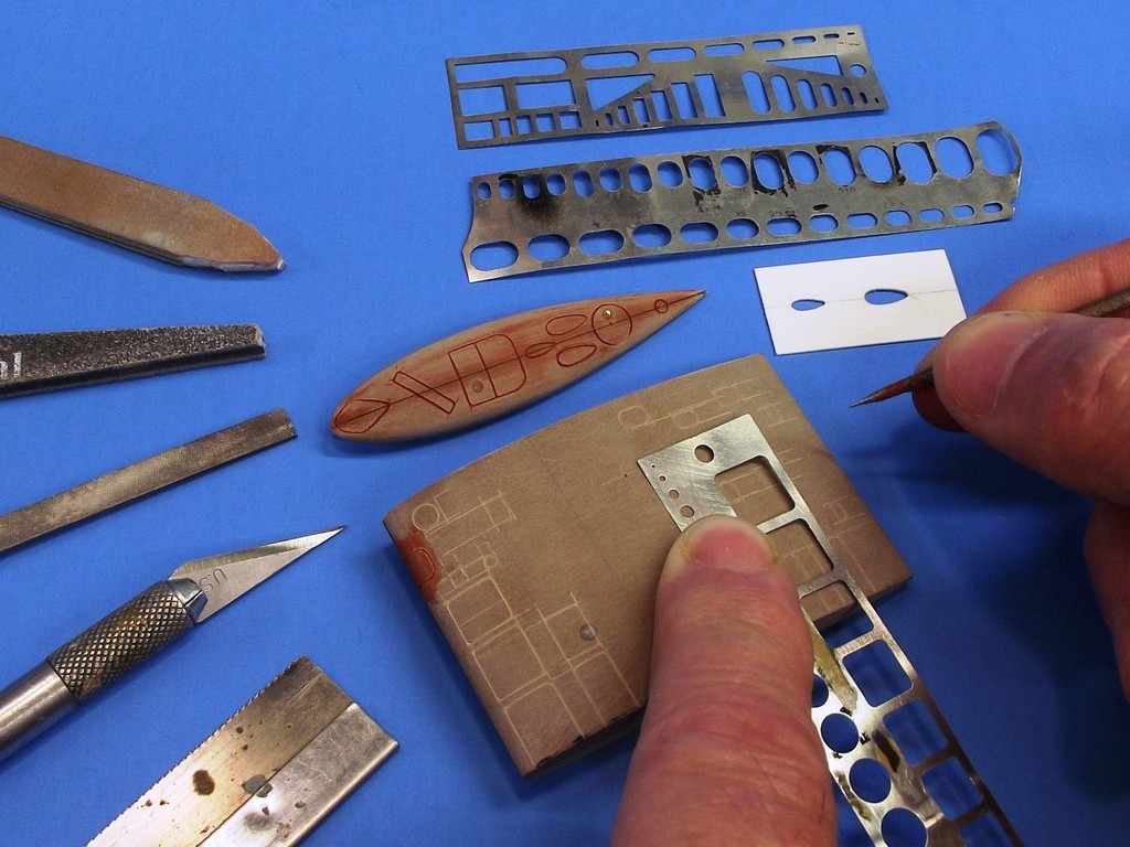
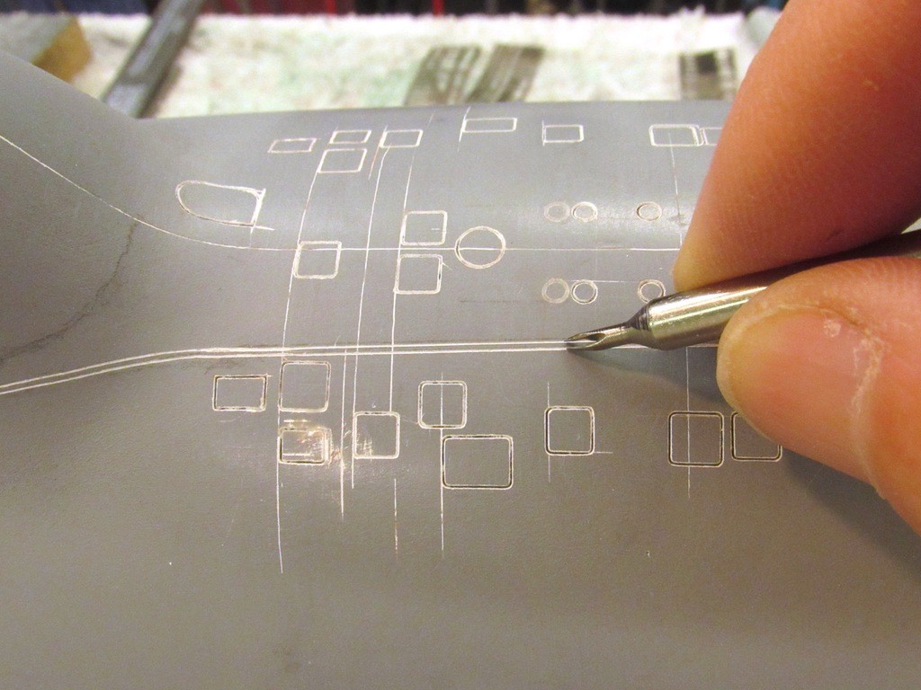
Here I’m using commercially available, stainless steel and plastic sheet engraving stencils to guide my scribe along as I represent hand-holds and access panels on the sides and top of this submarine sail master.
[IMG]file:///C:/Users/David/AppData/Local/Temp/msohtmlclip1/01/clip_image002.jpg[/IMG]
I used to make my scribing tool by simply taking a rat-tail jeweler’s file and grinding its tip to the appropriately shaped point – a sharp tip for a starting tool, a blunt tip for a finishing tool. Today I make a scribe by starting with a blank, a rod of 1/16” diameter carbon steel (tool steel in some circles). This tough, brittle metal will dull slowly, keeping its shape and point longer than softer metals. An important consideration as some of the work involves dragging the tool through fiberglass laminate – and silica glass is a very tough customer.
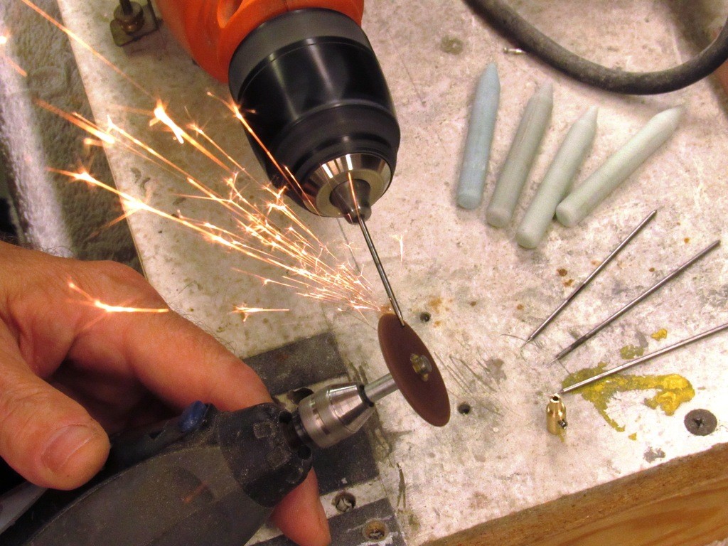
I secure a length of the rod into the chuck of a mini-lath and turn it. While spinning I grind in the working end of the scribe with a Carbide cut-off wheel. I keep grinding till I’m within a few thousandths of the desired tip diameter and then finish the job with files and wet-stone.
[IMG]file:///C:/Users/David/AppData/Local/Temp/msohtmlclip1/01/clip_image004.jpg[/IMG]
Typical tip diameter of a scribe is .010-.015 inch. The shank is CA’ed to a handle and I’m good to go. It’s good practice to file, sand, and wet-stone and polish the sides near the tip to minimize ware on the stencil used to guide the scribe during the engraving operation.
[IMG]file:///C:/Users/David/AppData/Local/Temp/msohtmlclip1/01/clip_image006.jpg[/IMG]
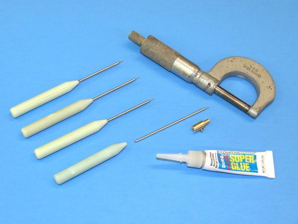
Typically I’ll engrave using two types of scribing tools: the first passes are made with a pointed tip, this tool does the cutting to approximate depth. The finishing passes are done with a blunted tip, this tool only refining the sides of the engraved line. In some situations the finishing scribe will be outfitted with the depth-collar to insure uniform depth of cut.
[IMG]file:///C:/Users/David/AppData/Local/Temp/msohtmlclip1/01/clip_image008.jpg[/IMG]
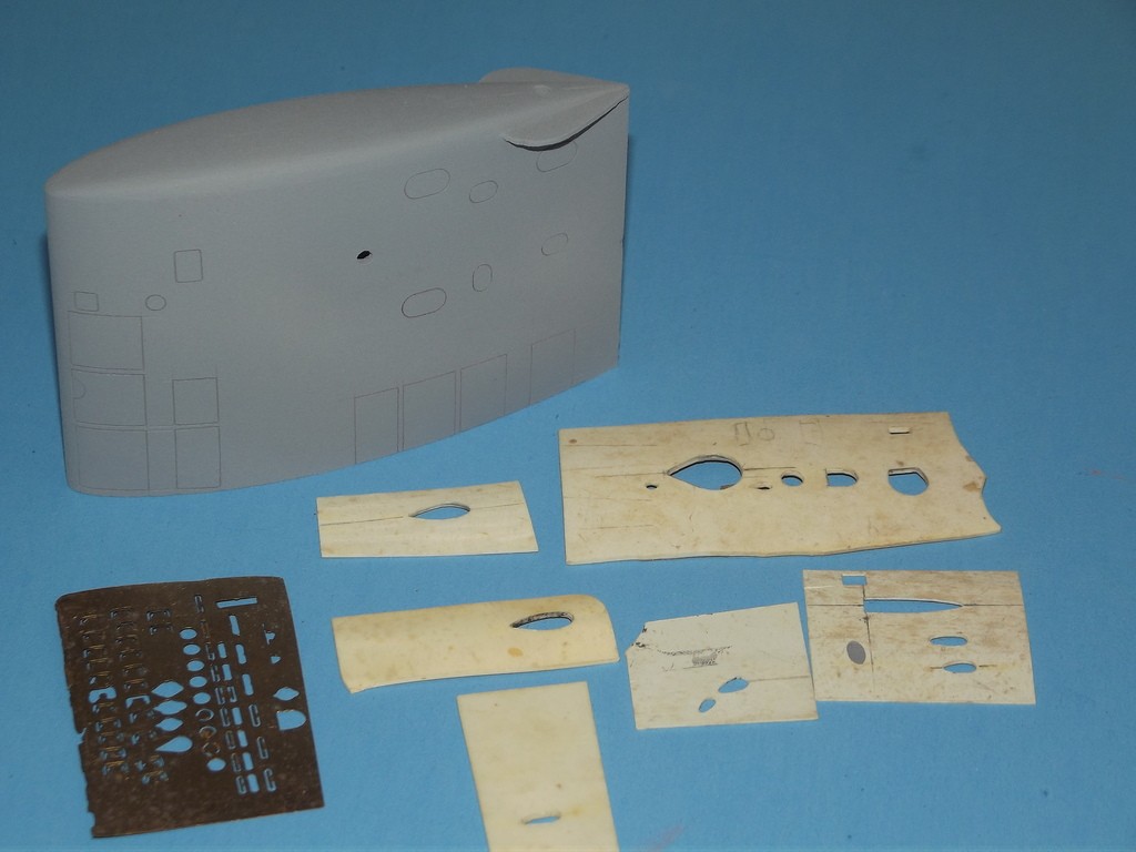
Scribing stencils take many forms and materials. Most flat, but some stencils are made to adopt the compound curves of complex surfaces. Example here is the top of this sail; the plastic stencil blank was heat-formed over the master to assume the gentile compound curve, then appropriate opening were cut into the stencil, those holes would guide the scribing tool as I engraved in the periscope and mast outlines onto the sail.
I also acid-etch metal stencils for specific, unique scribing jobs. You see one to the extreme left.
And I never toss a stencil once a job is done – often an old stencil will find use on a future job. I’ve amazed quite a collection of stencils over the years. These stencils fabricated from acid-etched plate, heat formed plastic, sheet metal, to GRP glove-fit types.
[IMG]file:///C:/Users/David/AppData/Local/Temp/msohtmlclip1/01/clip_image010.jpg[/IMG]
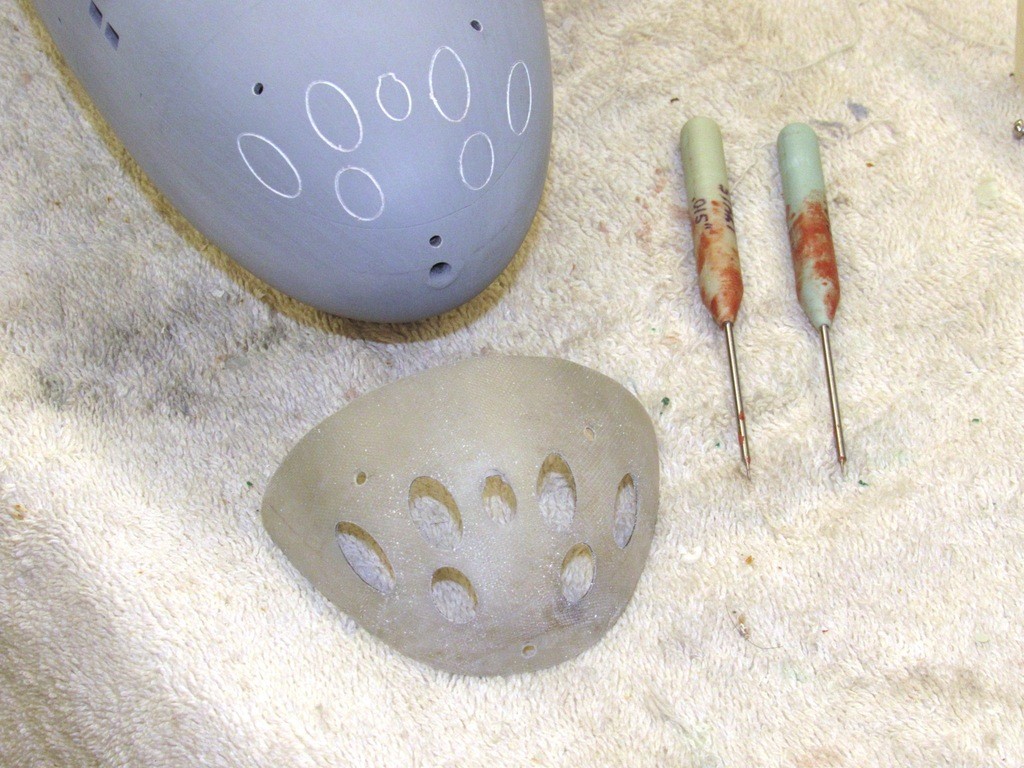
For extreme compound curves, such as the bow of this 1/96 ALFA model, I’ll lay up a fiberglass stencil blank to make a glove fit, and cut out the engraving holes as required; then use that stencil to engrave the lines required. Here you see the elongated ovals representing the torpedo tube shutter doors.
To insure a no-slip matting of the stencil to the bow I drilled and taped holes into the model itself, and secured the stencil with little 2-56 machine screws. No way no matter how much pressure I applied to the edges of the holes within the stencil would that stencil shift out of place! Once the job was finished it was an easy task to fill and fair over those holes.
[IMG]file:///C:/Users/David/AppData/Local/Temp/msohtmlclip1/01/clip_image012.jpg[/IMG]
Who is John Galt?Comment
-
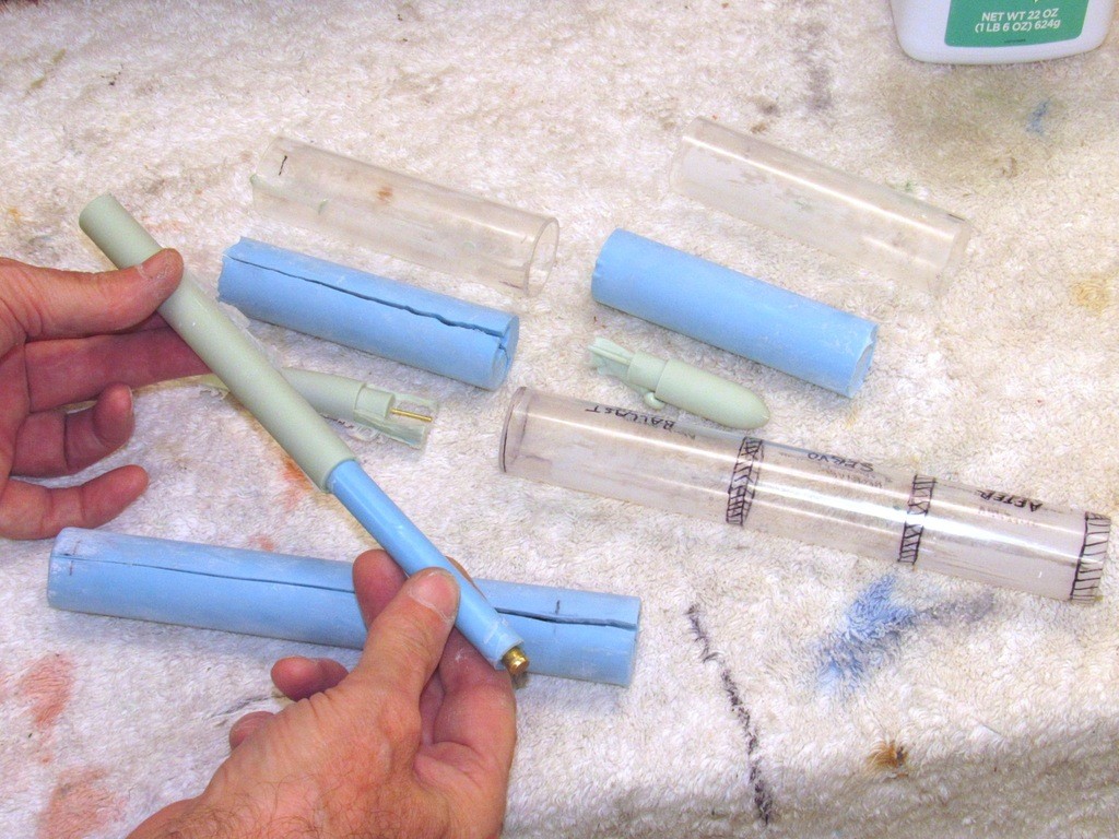
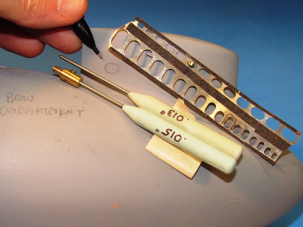
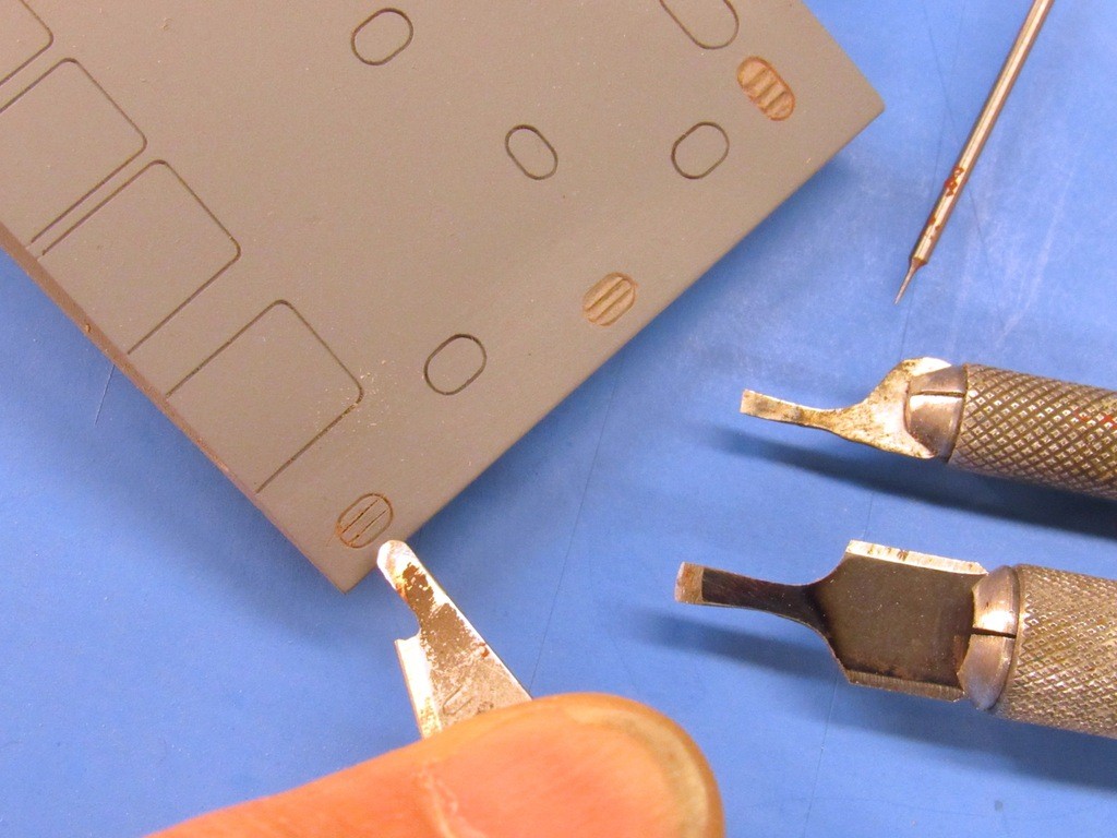
It’s good practice to first use a pencil, instead of the scribe, for the initial ‘check’ pass on the work. At this stage if you get the position wrong, or have chosen the wrong hole in the stencil, then no harm and no foul –you erase the pencil mark and try again. After validation of position and outline with pencil the process moves on to the engraving tools.
Many of the scribing stencils I employ are outfitted with pieces of sandpaper where they make contact with the models surface. This assures a no-slip tool when just using hand pressure to hold it in place as I maneuver the scribing tool with the other hand.
The scribe without the brass collar is sharp at the tip and makes the initial cuts. The ‘finishing scribe’, with the brass collar, is used to make the final passes and has a blunted tip – the adjustable collar insures a constant depth-of-cut.
[IMG]file:///C:/Users/David/AppData/Local/Temp/msohtmlclip1/01/clip_image014.jpg[/IMG]
A unique scribing tool is this two-point engraver, used to represent a submarines safety-track that runs the length of the deck.
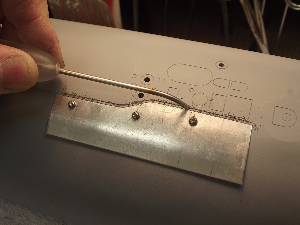
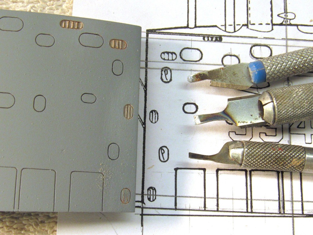
Aluminum stencils are used to guide the scribing tool over the hull of this model. As considerable lateral pressure would be applied to the edge of the stencil I insured it against movement by literally bolting it to the model with machine screws. The two-point scribing tool is seen above two of these stencils along with the screws used to secure the stencils in place.[IMG]file:///C:/Users/David/AppData/Local/Temp/msohtmlclip1/01/clip_image016.jpg[/IMG]
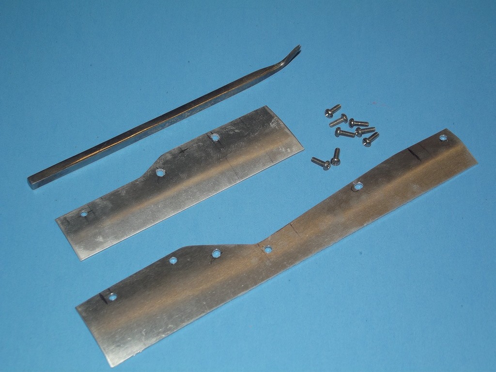
With the aluminum stencil bolted down tight I used a two-point scribing tool to engrave the two perfectly parallel lines that represent the safety-track atop the hull of this r/c submarine model. The long curved shank of the tool permitted me to rotate the head of the tool with great precision as I twisted it to conform to the curves of the stencil – failure to do so would produce lines of varying distance from one another.After the engraving job was done the stencil was removed and the bolt holes filled and faired.[IMG]file:///C:/Users/David/AppData/Local/Temp/msohtmlclip1/01/clip_image018.jpg[/IMG]
Another ‘special’ scribing tool used to under-cut an installed length of square section styrene rod to change its section to that of a ‘T’ is shown here. Careful grinding of a #11 X-Acto blade produced this tool.
[IMG]file:///C:/Users/David/AppData/Local/Temp/msohtmlclip1/01/clip_image020.jpg[/IMG]
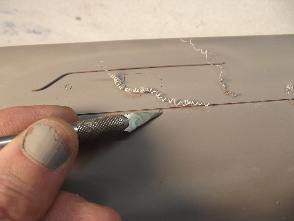
What was once square in section is now T in section. This feat of magic accomplished by scribing the two sides of the square rod.[IMG]file:///C:/Users/David/AppData/Local/Temp/msohtmlclip1/01/clip_image022.jpg[/IMG]
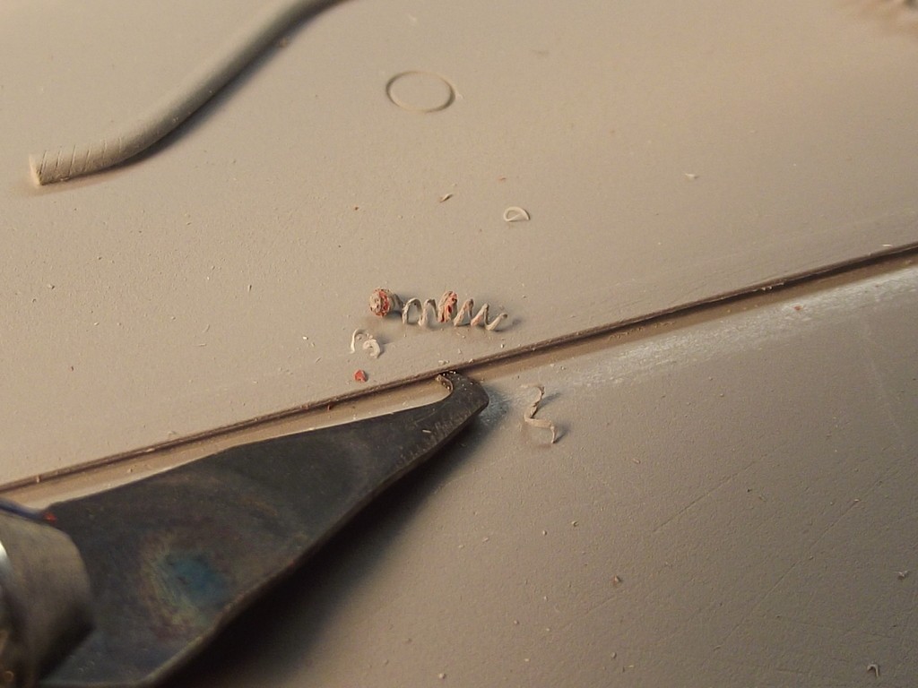
A similar scribing tool at work forming the safety track on another submarine model.
[IMG]file:///C:/Users/David/AppData/Local/Temp/msohtmlclip1/01/clip_image024.jpg[/IMG]
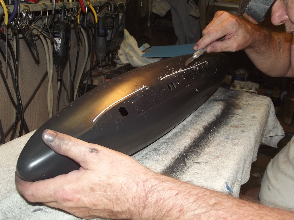
Once the engraved lines were cut into the models surface its good practice to free-hand the scribe within the established engraved lines in order to refine the shape, depth, and to correct errors like over-strikes, and tool marks. Inevitably, such localized repairs with filler or putty result in the goo getting into the engraved lines, which have to be re-established with the scribe to chase it out before the filler or putty dries/cures hard.
You see such tool-marks, datum lines, and over-strikes on the surface of this model. They will be filled with putty and the scribe then used to remove the putty from the previously engraved lines.[IMG]file:///C:/Users/David/AppData/Local/Temp/msohtmlclip1/01/clip_image026.jpg[/IMG]
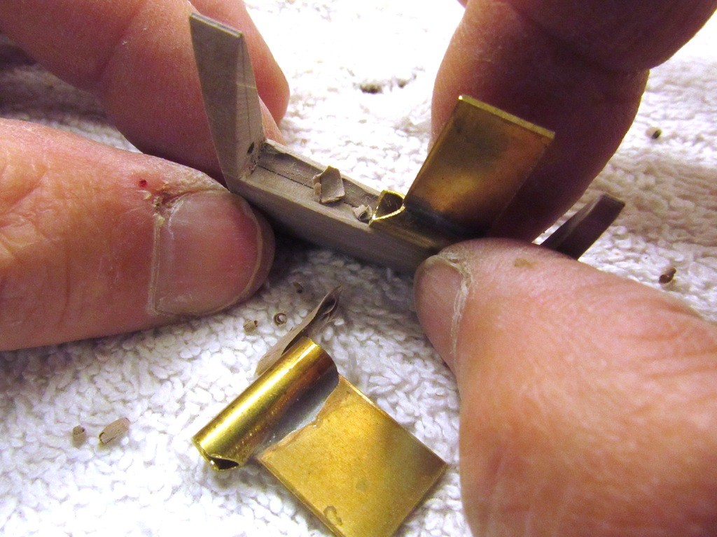
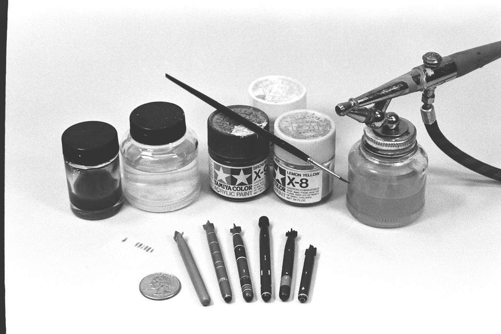
Sometimes I will augment the scribing operation with a low-torque drill and small bits. In this case I first pressed oblique holes into the body of this torpedo master and refined them with the shank end of a small drill bit. Note the brass tube used as a spacing-drilling jig.
[IMG]file:///C:/Users/David/AppData/Local/Temp/msohtmlclip1/01/clip_image028.jpg[/IMG]
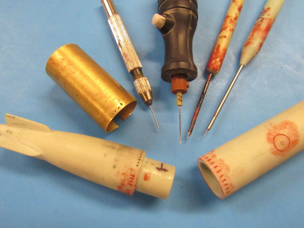
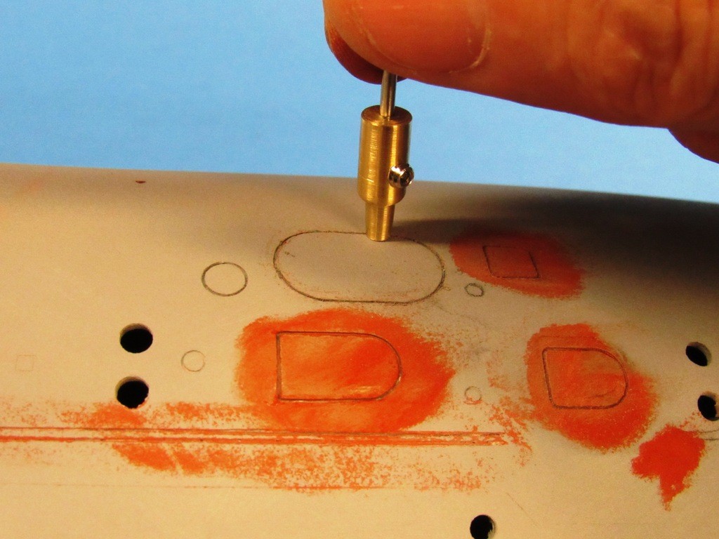
The more exotic engraving tools are these punches/circle engravers. These tools are formed from brass tube with the working end sharpened. I serrate the ‘blade’ of the tube to give it the ability to function as a hand-held radial saw: I press the tool into the work and rotate it a few degrees, press hard again, and rotate, periodically removing the tool to determine the depth of the circle cut into the model. As you see, there are all sorts of diameters and metals used to fabricate this type tool.
[IMG]file:///C:/Users/David/AppData/Local/Temp/msohtmlclip1/01/clip_image030.jpg[/IMG]
Who is John Galt?Comment
-
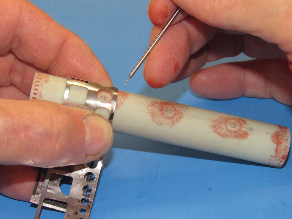
However, for the larger circles that have to girdle a cylindrical body like this, it’s back to the stencil. Note how this thin stainless steel stencil easily bends to conform to the circumference of the torpedo body. The sandpaper I glued to the stencil serving me well here by preventing it slipping over the work as I press the scribing point tightly against the inside surfaces of the hole used to guide the tool.
[IMG]file:///C:/Users/David/AppData/Local/Temp/msohtmlclip1/01/clip_image032.jpg[/IMG]
BLADESBy blades I also include the sub-set of ‘cutting’ tool, the saw. The blade, or knife, is a cutting edge so shape that it forces the molecules that comprise a substance to break their bonds and to fracture along the draw of the blade. The knife induces a localized failure of the substrate. The blade leaves little kerf – material lost to the cutting process – but cannot be plunged too deeply into the work without encountering great resistance. However, the blade, pulled spanwise along the work will scrape material away and in this way works as an ablator.
A saw, on the other hand, imparts many localized impact fractures (the teeth of the saw blade, each working as a gouge) causing localized failure of the substrate, little bits of which are thrown clear of the saw blade. A saw, unlike the blade, oblates the substrate. And in so doing produces a substantial kerf -- material lost to the thickness of the sawing blade. One has to account for this lost material during the layout process. Unlike a knife blade, a saw blade has the ability to dig deep into the work without experiencing an increase of resistance. Unlike the knife blade, the saw blade, because of the wide channel it cuts, relieves binding stress between the work and the saw blade.
OK. Below are typical commercially available X-Acto knife blades – these are representative of the bigger handle and blade types they offer.
[IMG]file:///C:/Users/David/AppData/Local/Temp/msohtmlclip1/01/clip_image034.jpg[/IMG]
And here are modified X-Acto-blades, each to serve a specific purpose. They were ground and sometimes bent to suit the job at hand. Apparent here are the two sizes of handles and blades X-Acto offers. To the extreme right is their ‘swivel’ knife -- great for following tight radius stencils or free-handing some types of camouflage masks. These high carbon steel blades are easily bent once taken to a red-heat – once shaping is completed the blade is taken back to a red-heat and quickly quenched in water to restore its hardness.
[IMG]file:///C:/Users/David/AppData/Local/Temp/msohtmlclip1/01/clip_image036.jpg[/IMG]
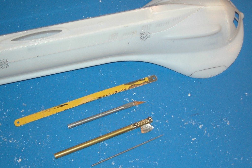
Here we see tools that work to saw, scribe, and cut the work. At the top is a simple hack saw blade; beneath it a knife; second from the bottom a razor saw blade set into a heavy brass handle for some ‘special’ work; and at the bottom a scribing tool.
The four tools used to cut away the superstructure portion of this kits polystyrene hull. First, I scribe the separation line; then followed that engraved line with the knife to deepen the cut; followed by use of the razor saw which is steerable to large radius curves (those curves seen atop the bow of the model); and, finally, the hack saw to finish the job.
Why the heavy brass handle on the razor saw? To ‘tune’ the tool to the job, that’s why. If you can get a cutting tool to resonate just right you will increase its cutting action substantially. Play with a tools shank or handle length and weight and, if you’re lucky, you’ll achieve this little slice of model-builders nirvana. More art than science.
[IMG]file:///C:/Users/David/AppData/Local/Temp/msohtmlclip1/01/clip_image038.jpg[/IMG]
These circular cutting tools are of the gouging type and are ideal for cutting concave trenches in the work. They are used to form the concave nesting trench within the trailing edge of a stabilizer that accepts the rounded leading edge of its rotating control surface. These tools are quickly made from brass tube. Note the sheet brass ‘handle’ soldered to the tool – to make pushing and guiding the circular cutting tool a relatively easy task.
[IMG]file:///C:/Users/David/AppData/Local/Temp/msohtmlclip1/01/clip_image040.jpg[/IMG]
Special cutting tools, here several types of ‘gouges’ have been ground to shape using standard X-Acto blades as blanks. Each of these tools serves a specific job on these little louvers I’m cutting into the trailing edge of this submarine sail master.
The right tool for the right job!
[IMG]file:///C:/Users/David/AppData/Local/Temp/msohtmlclip1/01/clip_image042.jpg[/IMG]
Initial shaping of the blade is done on the bench mounted grinding wheel. Final shaping is done with a hand held Carbide cut-off wheel spun in the chuck of a Dremel moto-tool. The blade is brought to razor sharpness with a wet-stone.[IMG]file:///C:/Users/David/AppData/Local/Temp/msohtmlclip1/01/clip_image044.jpg[/IMG]
Who is John Galt?Comment
-
How about putting a loop on the end of the rod in the center of the torpedo then use a hay hook/cork screw type handle
to pull it out of the tube. Be careful though we had a girl stab herself in the rear with a hayhook when the little jump seat she was on folded
up and she landed on the hook under the seat. ouch!
Attached FilesLast edited by Scott T; 12-18-2019, 12:18 PM.Comment
-
-
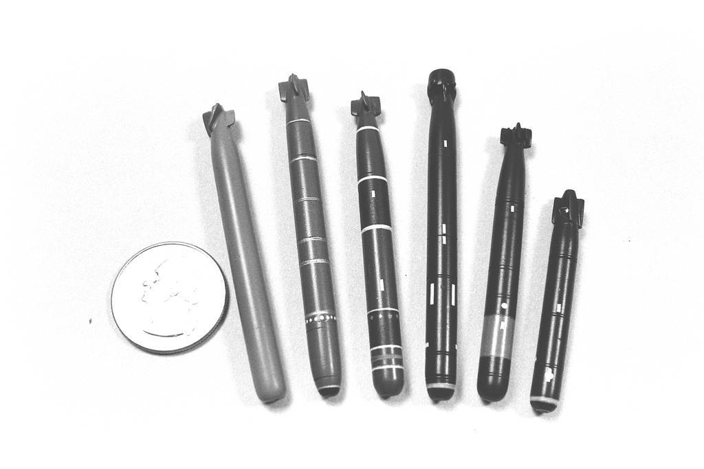
I was wondering, excuse me for asking, your small torpedo detail work on the master torpedo, the screw holes around the circumference of the torpedo will they be copied by the rubber mold? What size drill bit did you use to make them?
Will there have to be any rescribe work done after you pull a torpedo put of the mold?Comment
-
Thanks again for the lessons. So what is the size of the nozzle?
Comment


Comment