Guess this one will do.
https://www.hobbyking.com/hobbyking/...idProduct=8361
-
Romel,
I've got two different airvalves,
This one i use now inside the type 212 and type XXIII, you only have to plug up two of the outlets, you only need three.
This is the other one, you can regulate the rate of speed up and down, won't need that with the little LPB, but very usefull when using compressed air, i've got this one inside the type VII.
Manfred.Leave a comment:
-
Manfred can you give the specific make and model no. of the air valve you're using for your periscope mechanism?Leave a comment:
-
Thanks David, the frase, as usual, took some more time but she ready to be trimmed again, first solve another issue
Manfred.Leave a comment:
-
Very, very slick, Manfred. Great work as usual.
MLeave a comment:
-
No problem Romel, it doesn't have to be so big, we're not driving these boats in large waters, so it will be easely spotted.
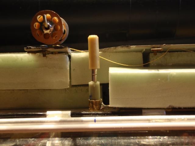
I went ahead with making the connection to the SD, it took me two times to get it right,
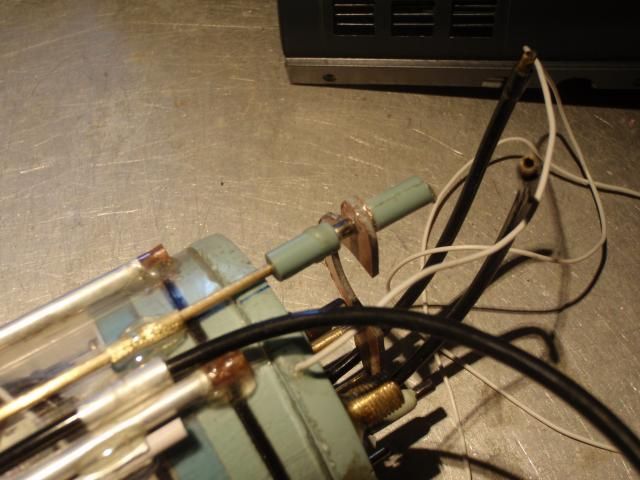
This was the first design, it proved to be too flimsy, the rod was way too flexible to transfer the motion from the servo to the triggerbar, if you have your SD placed inside the normal way, instead of upside down, it will work, simple because the distance is less.
At least it proved to me that the magnetic connection was usefull, so i designed a more robust version.
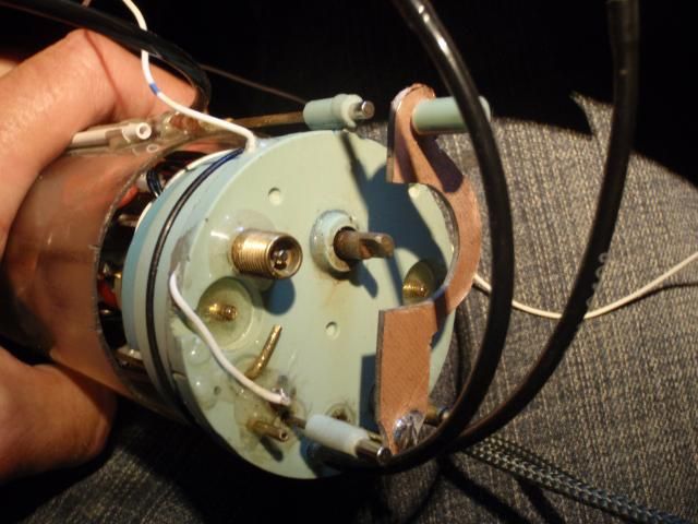
This is the Mark II version, made from CB, it's now possible to transfer the motion to the triggerbar, also made a vid to demonstrade the working order, it's being uploaded, be patient.
Also replaced the brass rods from the torpedosystem by Carbon one�s, it's now running much smoother than using lubrication.
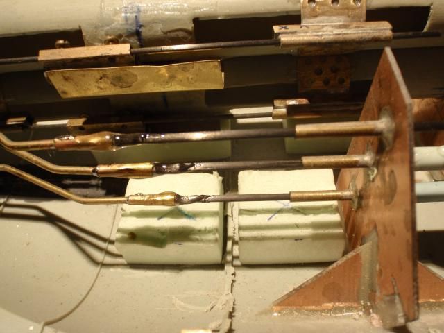
I simply cutted away each rod one by one and replaced them by carbon rods, soldered some tubing on both sides, and glued in the carbon rods with 2K glue.
Manfred.Last edited by MFR1964; 09-07-2014, 03:44 AM.Leave a comment:
-
Romel,
The buoy has the same size as my type 212, for me it's big enough, didn't have any problems to spot the buoy when my 212 was in trouble, most of the times i drive in dark open water near the shore, so a light coloured object will attrack your attention.
Manfred.
Manfred.Leave a comment:
-
Couldn't you have made the bouy bigger. That small pieces looks difficult to spot.Leave a comment:
-
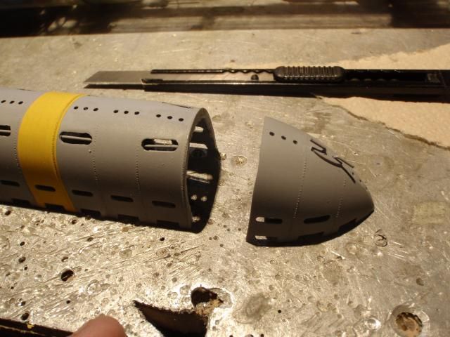
Last picture,
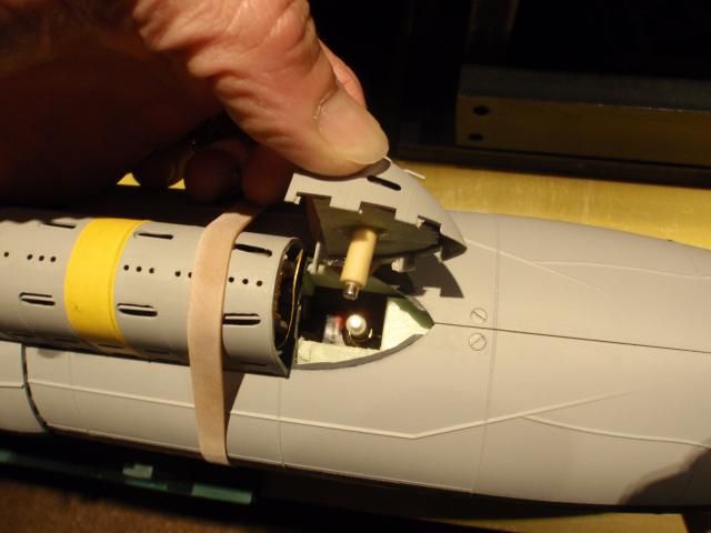
Opening up the rearpart by pulling it loose from the magnetic connection, last thing todo, making up the connection to the servo, testing the buoye, and trimming the beast,
Manfred.Leave a comment:
-
I've collected the pics, still have to make the connection to the servo, but i wanted to work back from the buoye towards the servo.
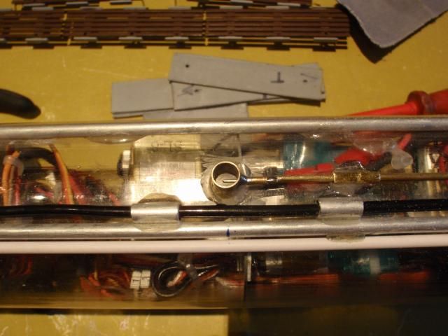
I copied the system from the 212, it works the same.
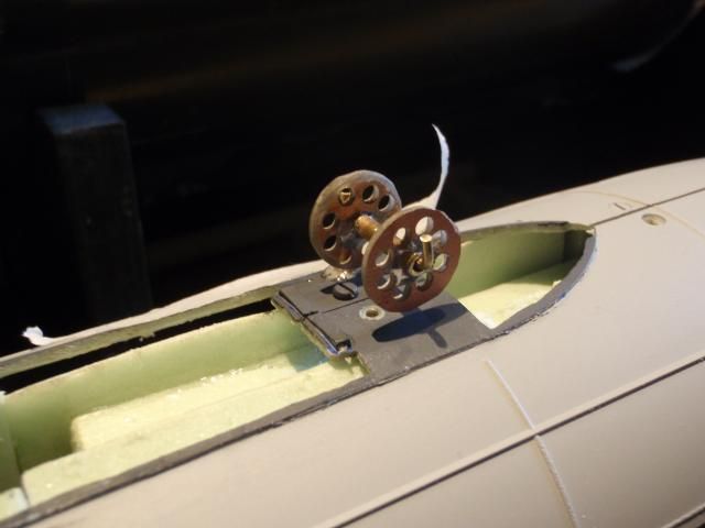
Made the spool and tried to keep it as light as possible.
It does fit exactly under the diesel exhaust, even with enough clearance to spin freely.
To make the connection between the buoye and locking system i've used again the magnets, this allows me to slide out the SD freely.
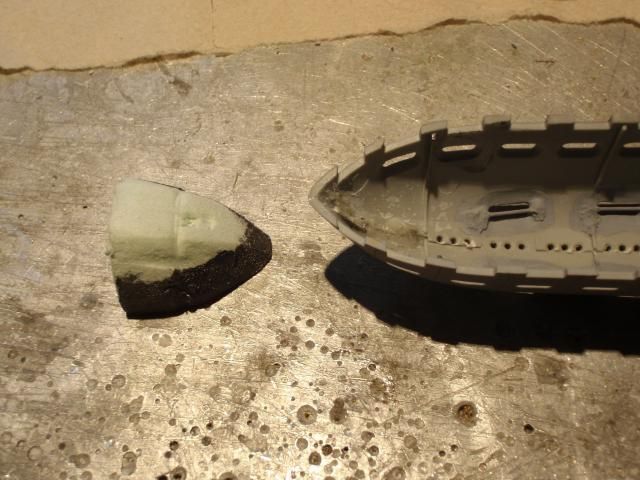
Shaped the foam to fitt inside the exhaust, glued it down with 2K glue.
A dryfitt to see if the hole to glue the magnet inside is positioned right.
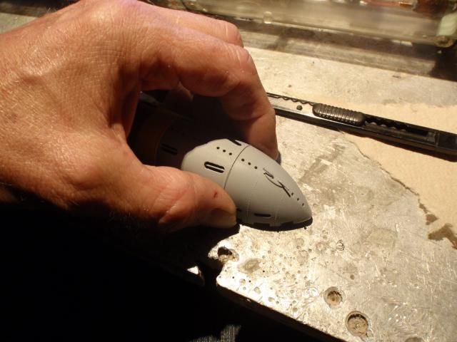
This was the most scary part, took the jewellers saw to cut free the rounded part, the cut is barely visible.
The advantage of using the jewellers saw is, you loose less material, so fixing the seem of the rearpart is easier.
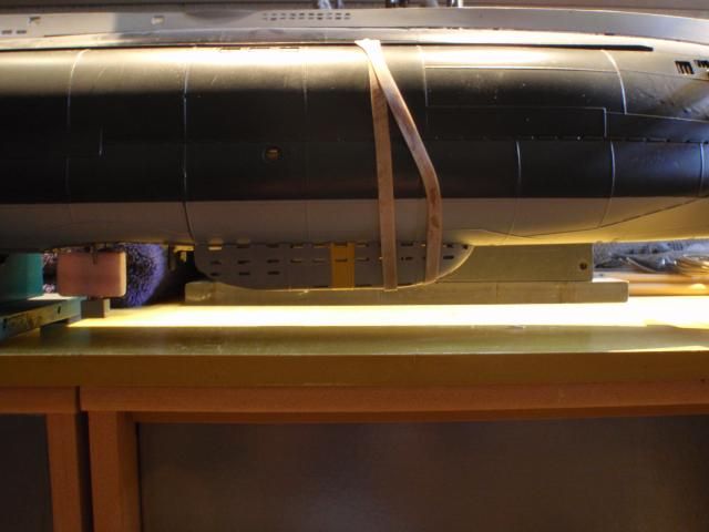
Had to place the hull upside down, this way the glue will stay inside the foampart instead dripping out.
It took about 24 hours to let it cure, again the seem is barely visible.
Manfred.Leave a comment:
-
It has been some busy weeks, made the release mechanism, the buoye itself and playing around to get this steered by the fourth servo inside the SD.
This weekend i'll shoot some pics from the progress, stay tuned.
Manfred.Leave a comment:
-
No problem Romel,
The length of both the rudder arms on top are 105 mm, lenght of the rudder control arm is 10 mm and the length of the diverudder control arm is 15 mm.
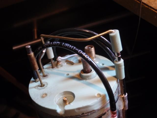
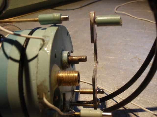
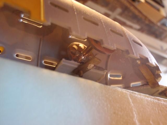
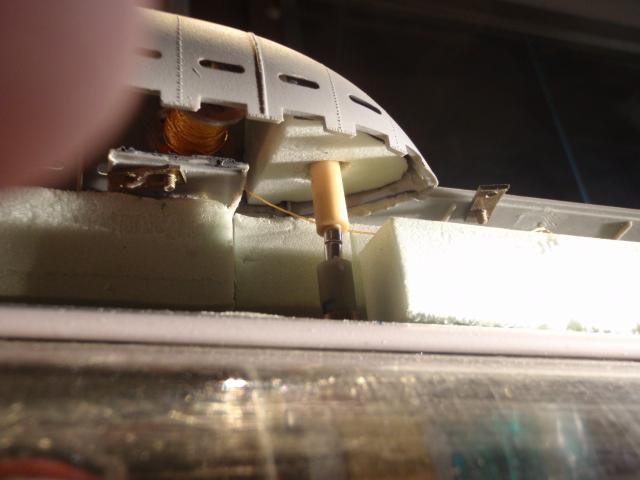
As for my journey for the resque buoye, the triggerbar is glued down on top, had a lucky stroke, since i had marked down the true center of the SD in the past, i could use this to center the triggerbar.
Glued down the triggerbar, used a small rat file to enlarge the inside of the bearings, this way i'm secured for a very light and smooth run, on the right you can see the beginning of the magnet couplers, this way you can still open up your SD without any problems.
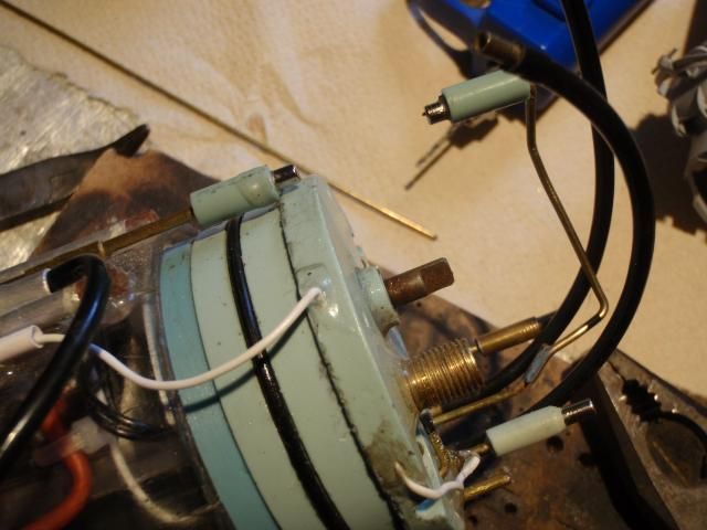
Since i've turned the SD upside down, i have to create a kind lever, which has to bend around the drivingshaft, first build the releasemechanism for the buoye itself.
Manfred.Leave a comment:


Leave a comment: