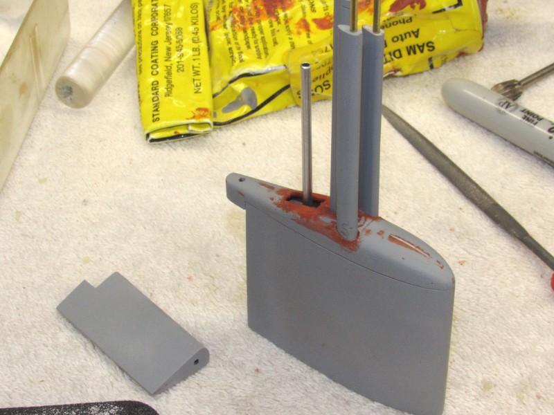
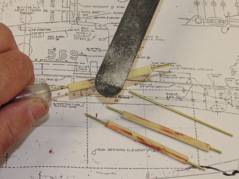
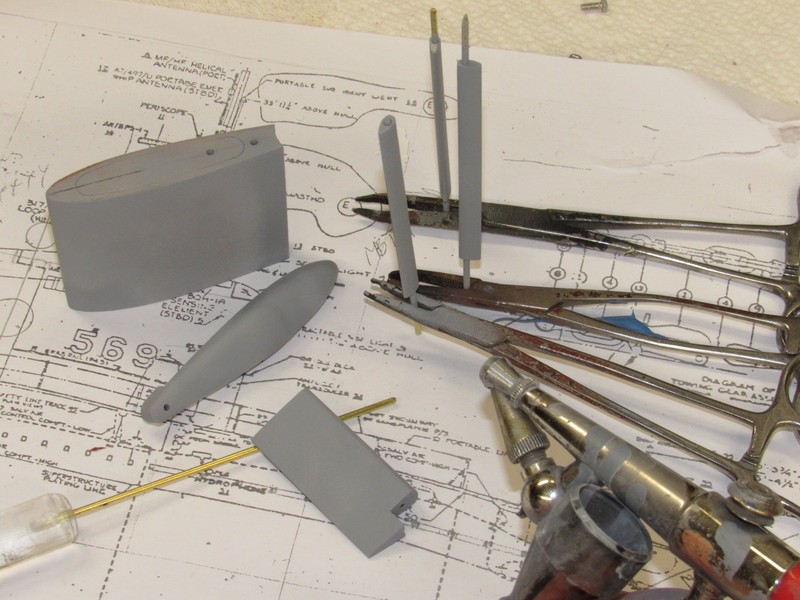
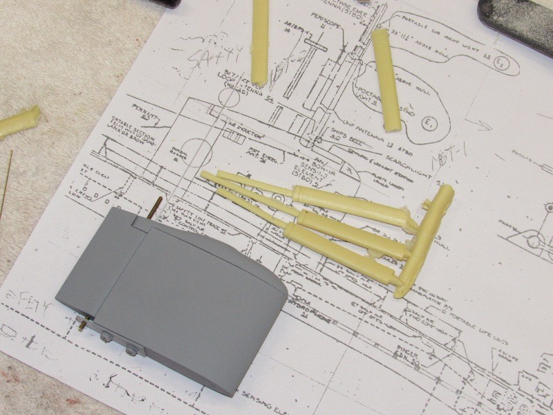
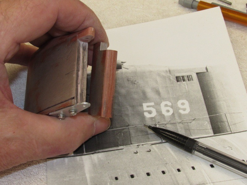
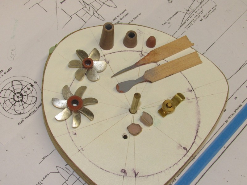
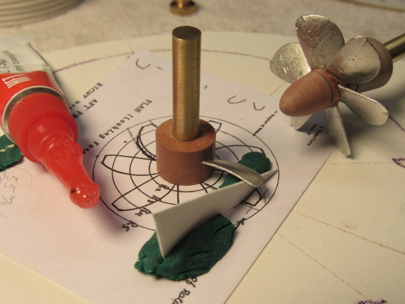
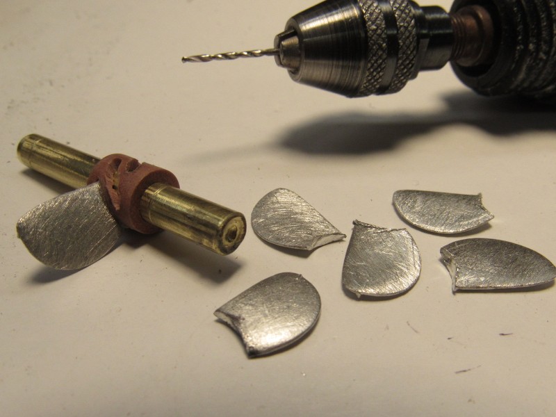
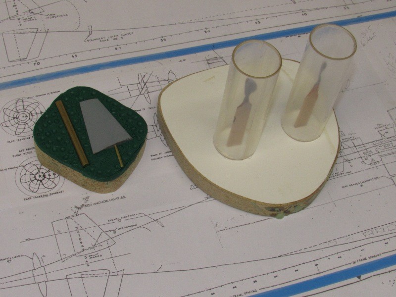
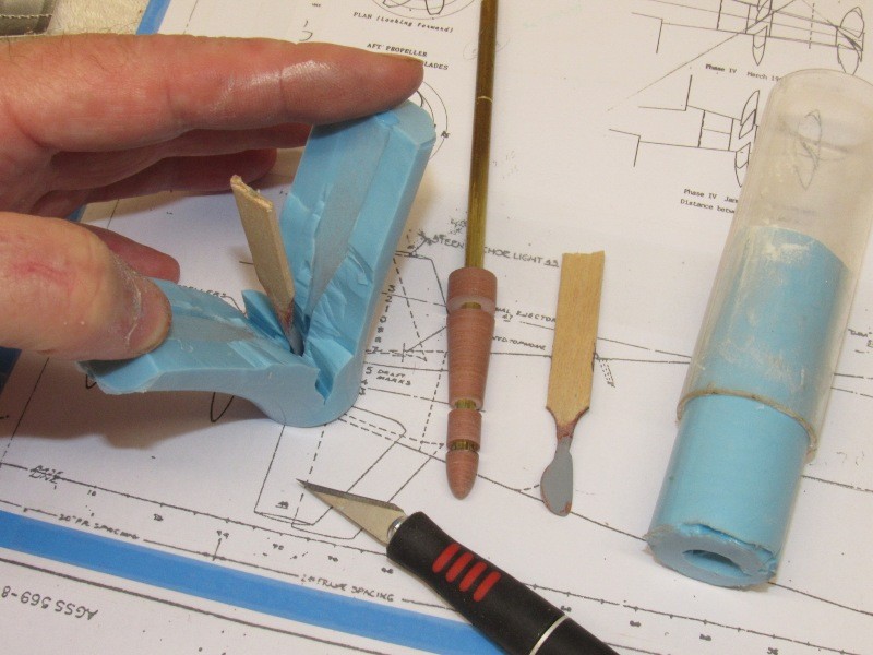
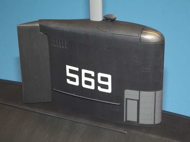
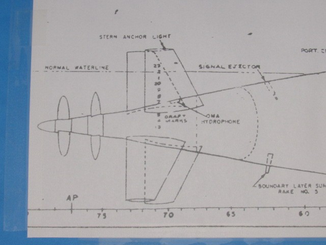
Test fitting the four masts. I�ll represent the bridge clam-shell type hatch pieces with engraved lines. As will be represented the two halves of the Plexiglas dome at the leading edge of the sail.
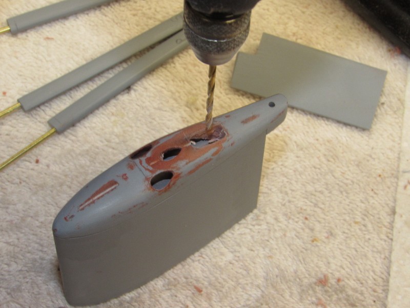
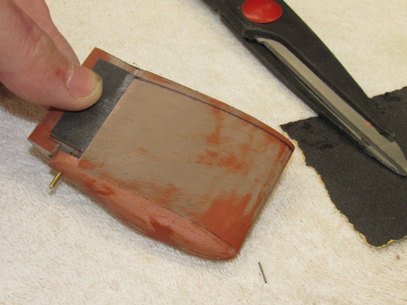
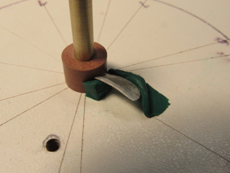
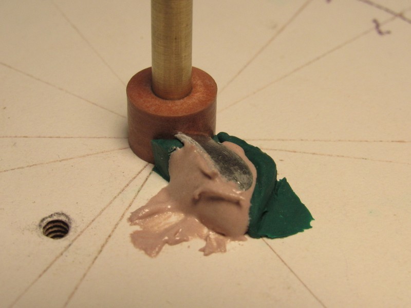
The sail has to be hollow to make room for the SAS snorkel mechanism as well as the periscope and masts foundation piece; and minimize the displacement of the eventual production sail parts. That work started out by carefully drilling pilot holes within the scribed lines at the top and bottom of the sail master � those lines denoting the wall thickness of the sail sides.
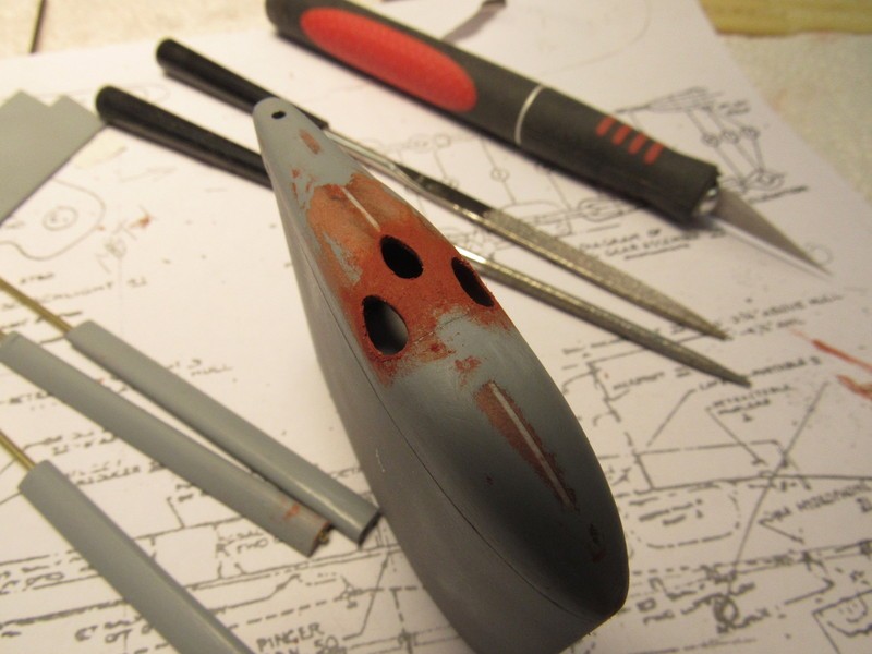
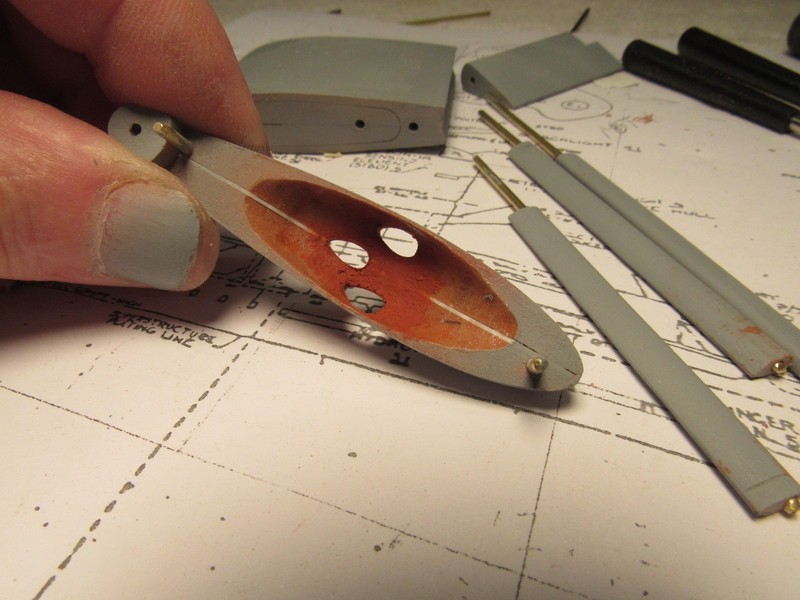
Note that I�ve already dug out the inside of the sail top piece. If a mast is not installed I want the viewer to see an approximation of the plate thickness one would see on the real thing. It�s all about scale modeling, after all.
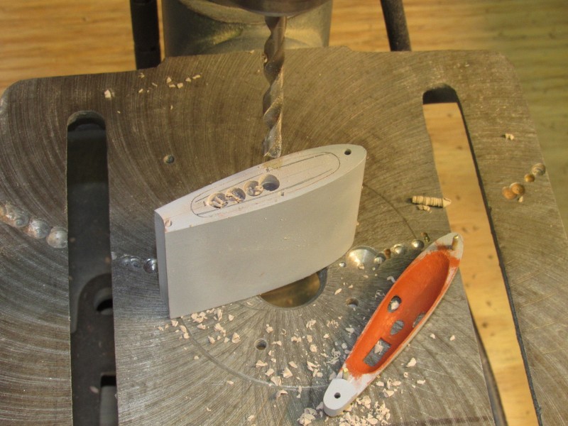
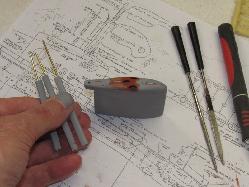
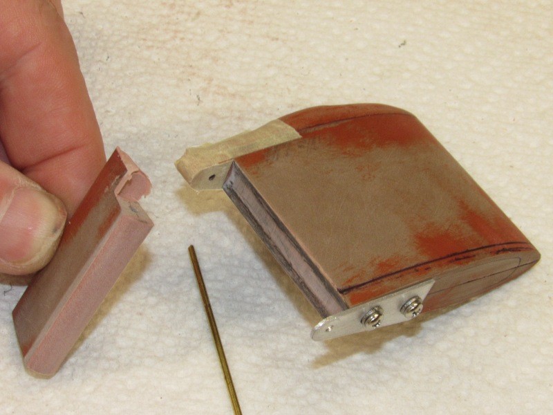
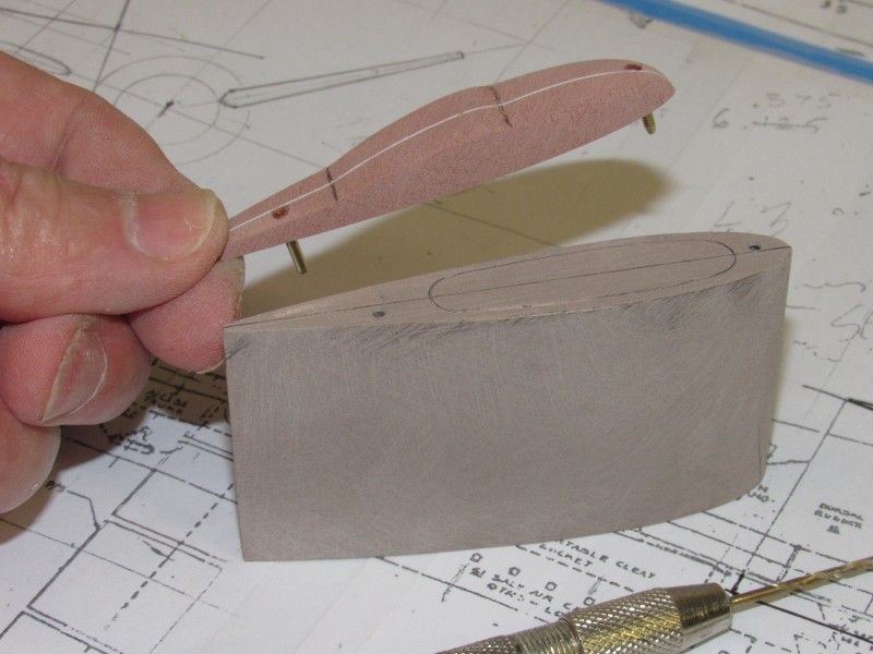
A constant diameter burr bit was used to rough out the inside walls of the sail master. Final shaping was done with round-files and sanding sticks.
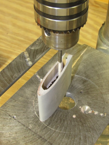
I made two sizes of the cavity sanding tool -- formed from brass rod turned to a �dome� shape at one end. Onto this dome was glued a small disc of #240 sandpaper. This disc pulled down to roughly contour to the dome shape of the sanding tool. These special sanding tools were then used to smooth out the putty applied within the sail top piece that filled the various dings and tool marks left from the moto-tool I used to render the thin wall thickness between outside and inside of the top sail piece.
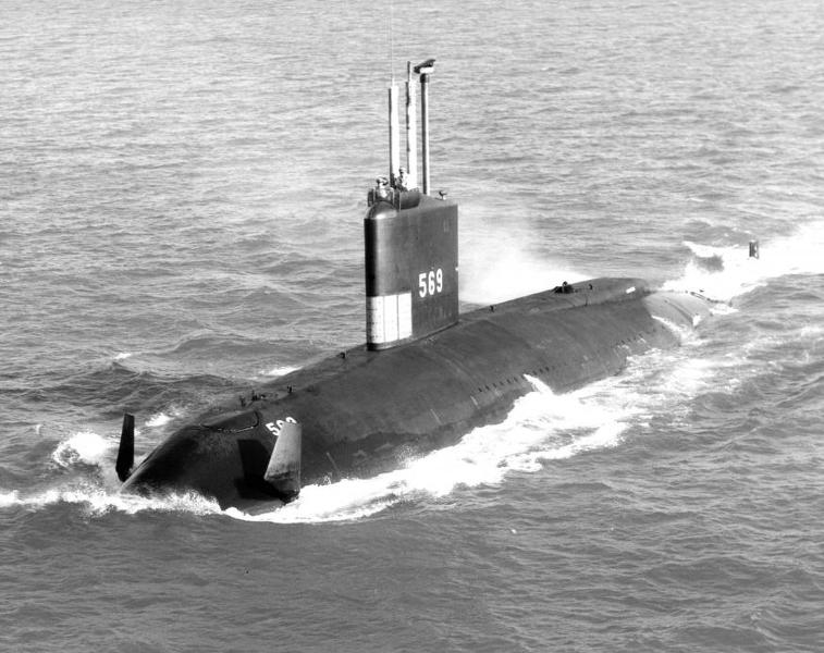
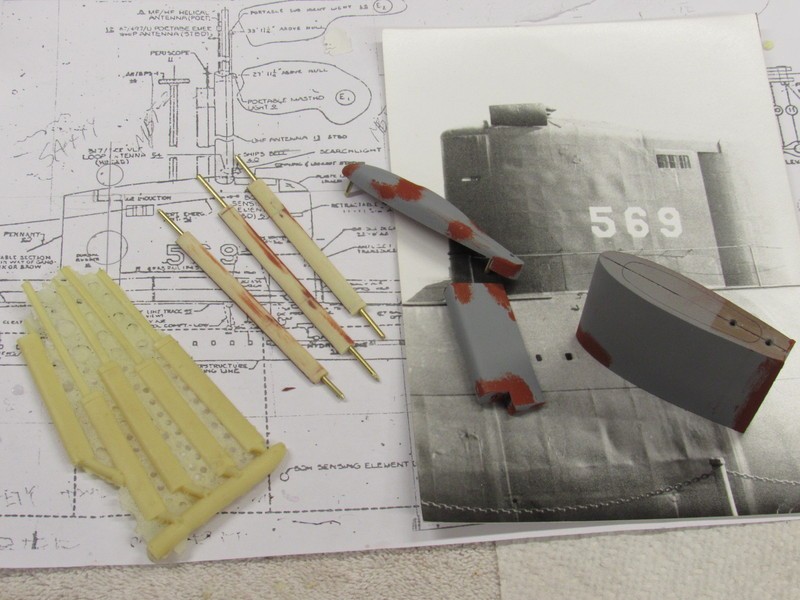
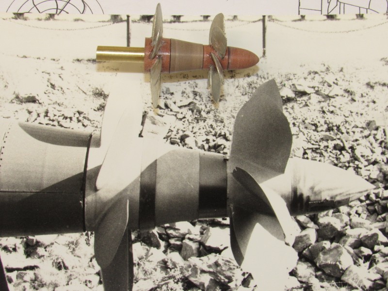
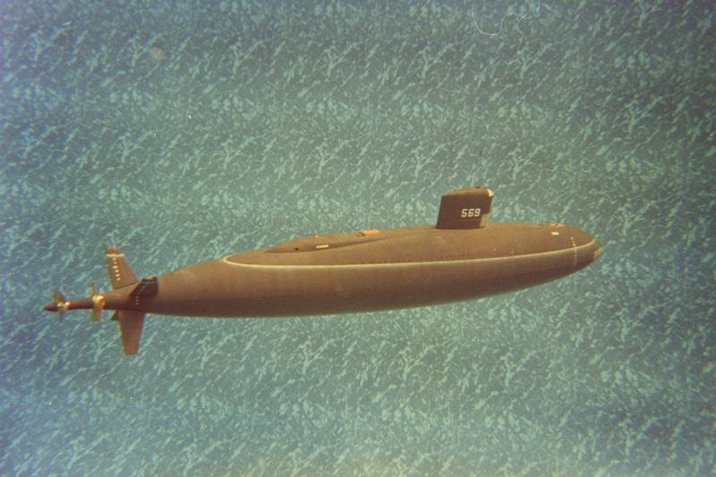
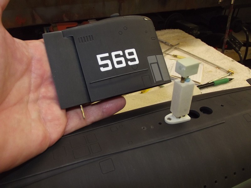
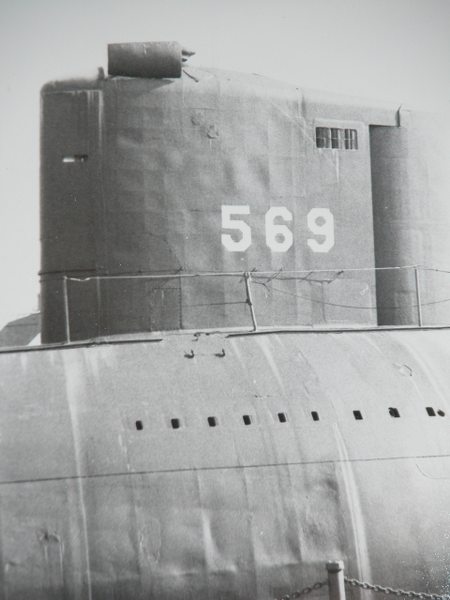
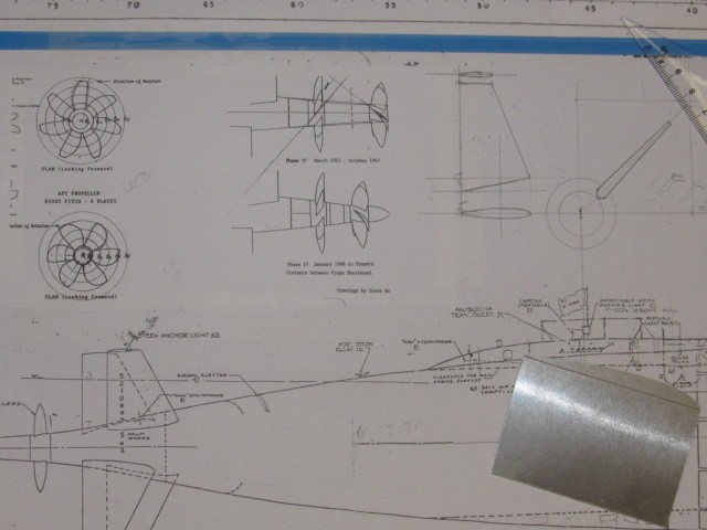
A major find in my researches was this grainy photo of the ALBACORE configured for her phase-2 work. The big deal here is the good look at how the whip antenna, search periscope (I assume it to be a type-15), and how a fairing plat was mounted above the surface search radar antenna. Solid gold! I can see I have to enlarge the diameter of the rotation device between radar antenna and mast. The drawings I have did not indicate that, and this photo only came to my attention a few days ago.
****!
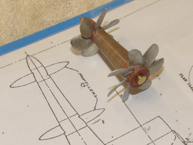
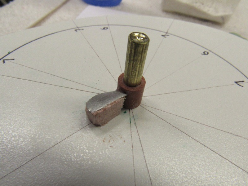
All pieces of the brass surface search radar master fit tightly together � this friction fit permitted me to solder the various pieces as a whole assembly. That work went very quickly. That #11 X-Acto blade will give you an idea how small this thing is in 1/96 scale.
Preparation and good planning is everything in this game.
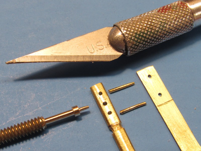
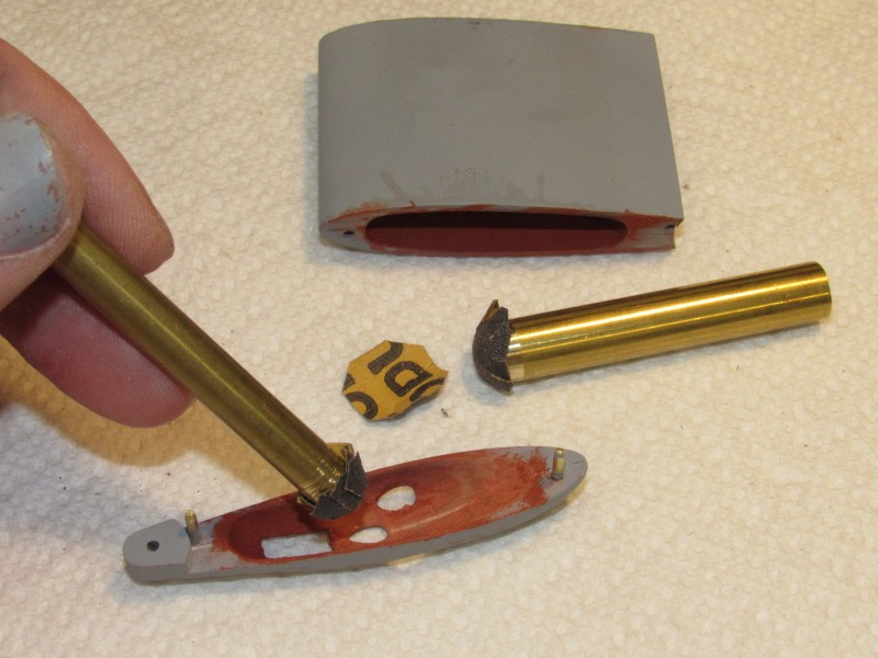
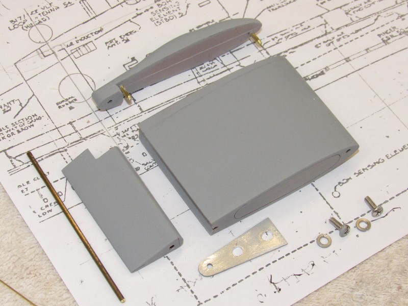
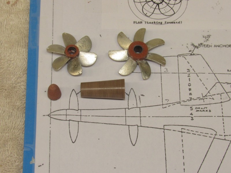
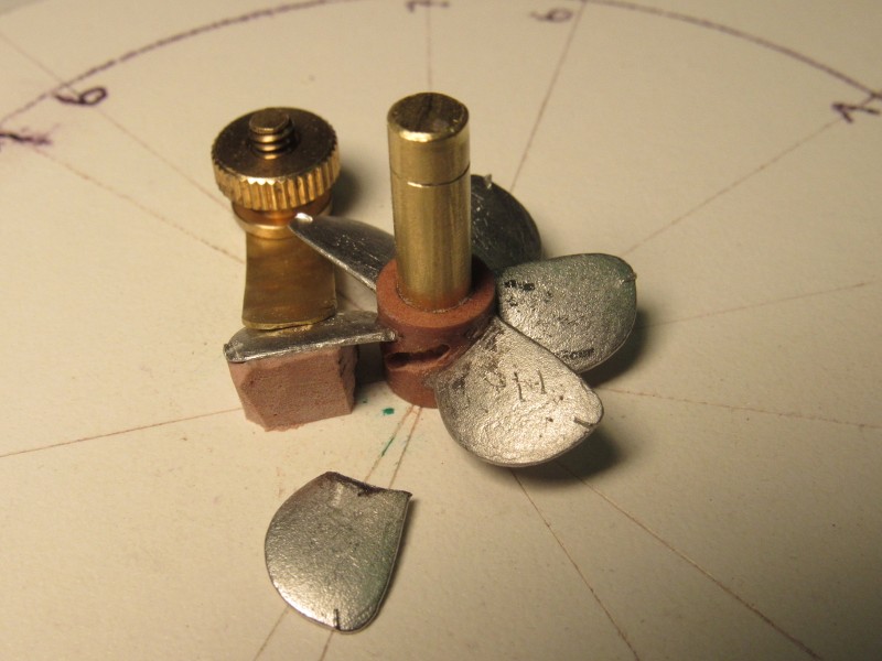
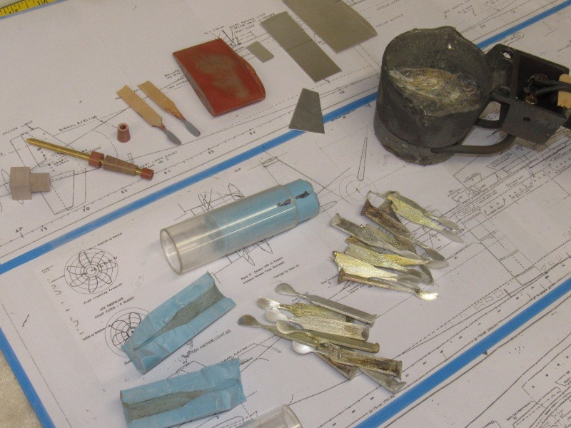
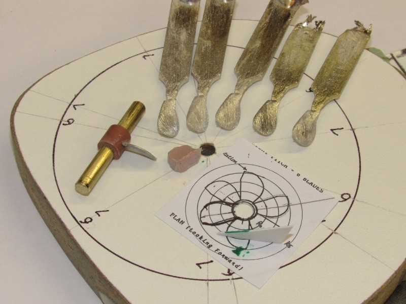
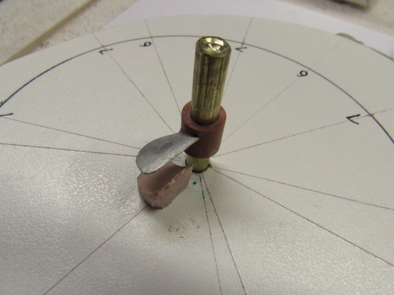
Brass stock was used to fabricate the surface search radar antenna and fairing plate that sits atop the antenna.
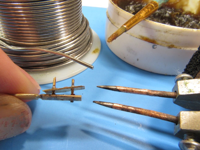
You may have noticed that the rotation device for the antenna was turned from a length of brass all-thread (5-40, if you must know!). As the brass used to fabricate all-thread is doped with lead, it makes it easier to machine; easier to cut the required thread. This �machine brass�, available in various diameter and thread cuts, turns out to be a much cheaper source of this alloy -- most brass is the tough, brittle �cartridge brass� and not suitable for machining -- than the stuff packaged as machine brass. The brass all-thread is a much cheaper version of machine-brass.
I took care to insure a tight interference fit between the four parts that made up the radar antenna-fairing assembly. This way all joints are in place and the work can be assembled and soldered in five discrete steps. Notice that I did not part the fairing plate or radar antenna from the brass stock from which they were formed � this gave me a convenient handle that made positioning the work an easy matter during the soldering operation.
Soldering started by slathering flux over and around a joint; placing a small sliver of Tin-Lead solder at the joint; the resistance soldering machines electrodes positioned; the foot-peddle switch stomped; and backed off the instant the solder melted, filleting the joint.
Frig�n magic!
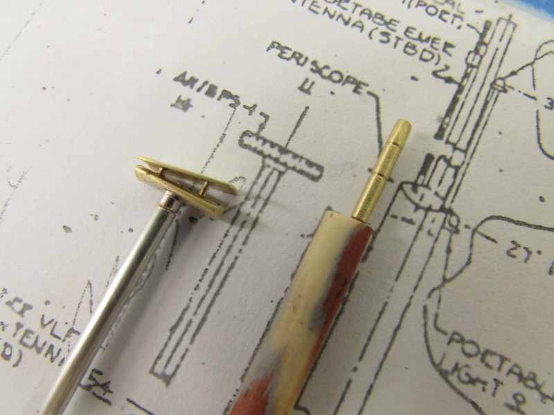
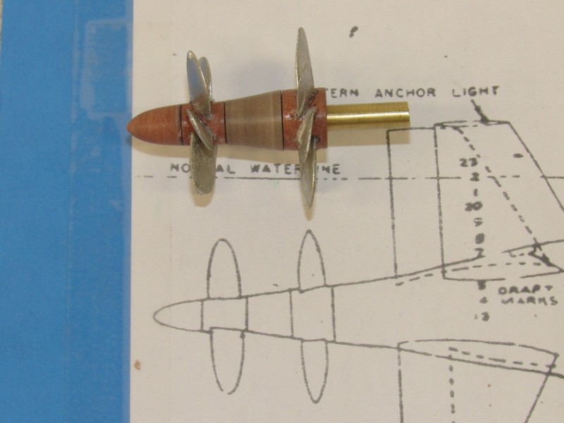
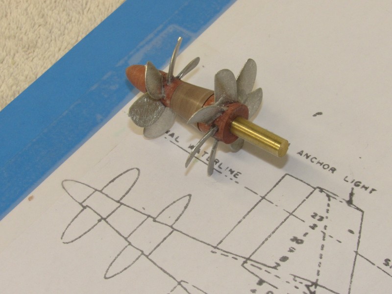
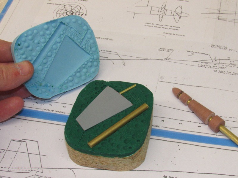
The brass periscope head and surface search radar antenna-fairing masters.
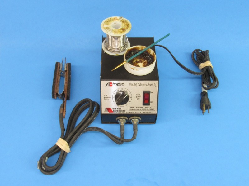
The resistive soldering machine is pricy but well worth it as it gives you the ability to localize the heat at only the point of union between the pieces you wish to solder -- you can make solder joints right next to other soldered work without fear of melting the previous work.
The resistive soldering machine works to heat the work two ways:
The ideal method capitalizes on the high resistance offered by a friction fit union. As current flows easily (no heat) on all parts that fit snuggle together (already soldered); and current bridging unsoldered parts, encounters high resistance (high heat) at the union, only that portion of the assembly gets the heat necessary to effect a good solder union. In this mode one electrode is placed on the body of the work, and the other electrode placed on the piece being joined to the work. Only after the electrodes are in place is the foot-switch stomped.
Or, if the part being soldered is physically isolated from an electrode, the area near the joint to be soldered is heated locally by placing the electrodes either side of where you want to solder a joint. A bit more local heat is applied in this case, but nowhere as broad a heated area as you would get with a traditional iron or flame. With resistive soldering you can leave your heat-sinks at home!
David


Leave a comment: