-
Who is John Galt? -
No you're not. We all just may have an age memory deficiency of some sort.
Would I need some sort of accessory package? Something with linkages, prop etc? I have not opened the Bronco box yet.Comment
-
OK David, will contact Bob.
Taking stock of my electronic devices, again. Here is what I have. Think I good but let me know if I’m missing anything. I’ll be using the same 75mhz transmitter from the Marlin.
AD2
Bat& Link monitor
BEC
Viper Marine 25
Keyfob remote on-off
I don’t have the Depth Cruiser. That looks like something I should add. Maybe add it to the Marlin/XXIII sub driver.Comment
-
What about the Depth Cruiser? Must have?Comment
-
I am not sure it is a necessary, a leveler yes, but I bet it will make it sweeter ride!If you can cut, drill, saw, hit things and swear a lot, you're well on the way to building a working model sub.Comment
-
You've already given up a nut by using an angle keeper. Keep your remaining ball and just drive the damned thing like a real man... or are you going to be a eunuch and install the depth-keeper? You Woos!
You gonna drive that beast or are you gonna just be an interested spectator?
DavidWho is John Galt?Comment
-
Figured if the SJ is going to be a hot rod underwater, why not let it go crazy at a set depth. Could be a sweet ride like Tom said.
LOL and maybe less of a chance playing lost and found.
Giving myself this month only working on the SJ, get myself excited for getting it done so I'm not a spectator.
BTW it's fun just to say something to get such an awesome colorful answer! Love it!Last edited by Ken_NJ; 01-08-2021, 07:37 PM.Comment
-
How about a diagram/photos on how to wire up the remote key fob switch?????????
Thx,
FarlanComment
-
Will do Farlan, when I get to that point I will.Comment
-
I'm working on setting up the electronics on the electronics tray. I like to keep everything neat and clean. I don't like y-cables which I determined I need two of them. Y-cables introduce a lot of sloppy appearance trying to coil up the extra cable. Since I can make PCB's here is how I eliminate the y-cables. Basically I make a PCB with three headers on it. Three servo cable ends plug into the PCB which you can see eliminates all those extra cables. Here is a picture of one of the PCB's in my Marlin which has been in use for about 8-9 years.
Normally I make the PCB traces in a free electronics program on the computer. I previously used PCBExpress (Windows). I print on a B&W laser printer but my printer stopped working so I have to do it the following way. I don't like this method, it's sloppy looking, and not to my standards. I'll soon get a replacement laser printer. For now.... I laid a grid on a copper PCB sheet with 1/10" spacing. That is the same spacing on the servo connectors. I then used a Sharpie to cover the three points where the header will mount to. I made sure the marker was on the heavy side.
Ferric Chloride is used to etch the PCB. I still have some from Radio Shack but you can buy it online in mostly powder form. The etching process works best when the FC is warm so I heat it in a beaker on my coffee hot plate.
The FC is poured into a plastic tray. DO NOT use any metal, it will start to etch. Drop the PCB into the solution and wait. Besides warm FC, agitation helps, so I grabbed the white spill tray and slightly slide it back an forth.
When all of the copper is etched away it looks like this.
I used acetone to wipe away the marker. You can see the blotchyness of some of the copper. That's due to the marker not covering the copper fully. Use an ohm meter to check for continuity from the end of each trace. If there are any opens they will usually be corrected with solder later on. Also check for shorts between each trace. Use and exacto knife to remove any shorts. I already started drilling .030 holes for the headers. Again, this looks sloppy to me but it will be functional.
This is the reverse side. I used a round file to clean out the holes and sanded this side of the board to remove any burrs.
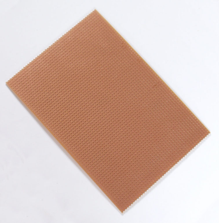
This is how a PCB should look, unlike above. This was done on PCBExpress and with a B&W laserprinter.
I'm only doing two for now, so I cut some off.
The headers were on a longer length so I cut them off to three to a section. I made sure the pins are not too long or short by inserting them into the connector. The pins can be slid in and out with pliers.
The final product. At this point check continuity between each pin in each row. Also make sure there are no shorts between rows. If you have an open pin in one row, you should be able to bridge the pins with solder to eliminate the open.
Solder side.
The traces are ground, 5 volts and signal. When you plug in the servo connector you need to be sure the connector goes on 90 degrees to the solder traces! Otherwise stuff will not work!
This is not rocket science. Anyone should be able to do this. For the Ferric Chloride, it will stain your hands so be careful there. And it will eat away at metal tools. Use plastic tweezers when picking PCB's out of the FC tray. Hope you get something out of this. I'm guessing this might be easier than doing 3D printing, just saying. I haven't done 3D printing yet.Attached FilesLast edited by Ken_NJ; 01-14-2021, 05:02 AM.Comment
-
-
Thank you Ken! You make it look simple. That is a super cool solution to a Y cable.If you can cut, drill, saw, hit things and swear a lot, you're well on the way to building a working model sub.Comment
-


Comment