
 Tweet
Tweet
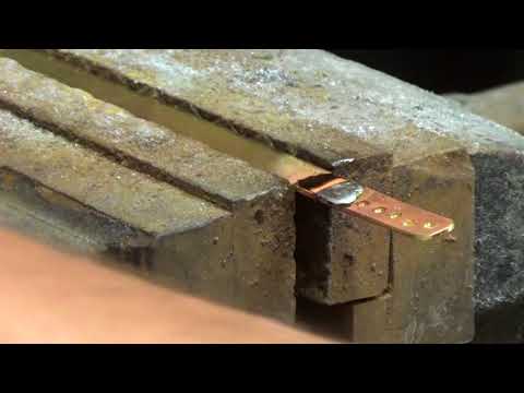
Yeah, the Arkmodel kit designers made a mistake when they were designing the rudder linkages. The horns are too long and hit the hull. I fabricated my own from a bit of brass flat stock and a plated wheel collar. Video here.
-
Here is the start of the internal wiring. The main on/off switch is built into a styrene holder, and the main fuse installed beside.
The on/off switch pushrod will have to run the entire length of the WTC, paper templates are used for the electronic components.
The three servos are installed and pushrods added, the rear plane servo (the side ways one), needs to be dropped lower.
The motors get wiring and supression kits.
This the rear end of the WTC, upside down, the price for the 900ml piston tank is very tight clearances around the prop shafts and servos, I added a joint in the water inlet as I have to take the servos in and out frequently to get alignment.
Right way up, the wiring for the speaker and lights is led down the WTC towards the batteries, and there's just space for the Receiver, and the space beside the 4 block connector will take the pitch controller. The rear plane servo is sitting up against the top tech tack rod, the two pieces of plastic help hold it in place. The motor wiring comes through the floor and will be sorted next.
The Boattrainman
Last edited by The Boattrainman; 06-12-2018, 04:06 PM.''We're after men, and I wish to God I was with them........!''Comment
-
Rob
Wow all great looking, wonderful. Thanks for the photos , cant wait to see her in the water
BillComment
-
Thanks Bill, how's your build going.
I'm doing the wiring in prep for the arrival of the ESC, Sound Module, Pitch Controller and Ballast Tank Switch arriving at the end of the month (me Birthday!), plus I want as much of the internal stuff done as possible before I do a trim test.
Long way to go yet, 15 months in, still a few more to go yet........
Rob''We're after men, and I wish to God I was with them........!''Comment
-
Progress slowed a bit over the summer, but I finally got the electronics sorted.
Here are the four modules.....
Mtroniks sound, Mtroniks 40amp ESC, Engel Ballast Tank switch and Pitch Controller.
They just about fit on the equipment tray over the batteries, the Mtroniks units are held in place with a plastic surround and the Ballast switch is screwed down.
I made a main switch from styrene, with a 25amp fuse and a green LED to indicate power is on, it shows through the end plate as the Ballast Tank Switch blocks the other end.
Here is the final install.
The positive bus bar is under the Ballast Tank Switch. The green switch turns on the ESC which also powers the Receiver, the red switch the lights and the yellow switch the sound system. Effectively this means all items are separately switched as the main switch turns on the Ballast Tank unit. For normal operation all ancillary switches will be left in the on position, and the main switch {via the brass pushrod to the rear and exiting the boat} will only be used.
The negative bus bar is behind the red and green switches out of the way.
I went overboard on the wiring, it's all 17amp automotive, as with two large motors, I want a bit of a margin for overheating. All sound and and lights is just 5amp.
I got a name plate made by my usual maker to match my other models.........
.....................and finally, part of the distraction is I was gifted a kit for a Steam Launch with working Steam Engine, so I've been sharing my modelling time with this beauty.
The BoattrainmanLast edited by The Boattrainman; 07-31-2018, 05:20 PM.''We're after men, and I wish to God I was with them........!''Comment
-
The On/Off switch is stabilised with a small fitting, that can be removed to change the bellows.
The speaker for the sound module is a fully waterproof 2inch item (2 bucks from China), and is located under the aft deck.
I re-made the support at the hull break, it was flimsy from all the cutting and hacking. The new one is styrene backed with a 0.5mm brass plate for strength.
For added security I added a locating pin of a 3mm machine bolt with 6mm head that locates into a slot in the fore section.
Here it is about to locate in the slot, it stops any attempt at missaligning the two hull sections.
So the wiring and rear section is complete, lots of snagging left to do, here it is top and bottom.
This is officially the most complex project I've ever worked on, but getting into the final stretches is very rewarding.
The BoattrainmanLast edited by The Boattrainman; 08-03-2018, 04:00 PM.''We're after men, and I wish to God I was with them........!''Comment
-
Now for the rigging, an area that can make or break most model boats.
Thankfully, it's just the three aerials and the four safety wires around the conning tower.
I used a wooden board to get the lengths right and not damage the sub during construction..........
..... and used the 0.75mm good quality rigging cord (which I hung from the ceiling with heavy weights for about three weeks to remove as much tendency to stretch) that came with the model and some oblong fishing line items for the insulators.
As the aerials will stretch with time, I have left a short section at the end on all three aerials that can be replaced rather than re-do the whole thing. The oblong insulators look daft in bright colours but will be toned down during painting.
All the rigging is terminated by a loop with a 5mm length of 2mm heatshrink sleeve and a dab of superglue (no knots!), once a bit of heat is applied the heatshrink squashes the superglue and makes a tight fit.
The safety wires terminate in bottlescrew tensioners, the items I had in my spares box were whitemetal but were poor quality, so I made my own from 1.5mm brass tube and some pins.
They are temporarily attached to the model with one end just tied as they will need to be tensionsed on the final model once painted.
Not as ardous as my last model ship that took 3 months to rig, the final piece will be the three jumper wires from the tower to the aerials, but again they cannot be sorted till the model is finished.
The rigging will be all permanently attached to the tower with figure-8 wire loops, but removeable at the ends as the tower comes off.
The Boattrainman
Last edited by The Boattrainman; 08-12-2018, 12:08 PM.''We're after men, and I wish to God I was with them........!''Comment
-
To finish the rigging, the three jumper cables need to made from stripped cable, four wires are wound using my dremel, and then thye are flooded with super thin superglue to keep them together. Thread or light rigging cord won't work, it would be too fragile plus it will never hang like real cable.
There's a balance between scale appearance and functionality, the wires are routed from the insulators via brass eyelets to the aerials.
The tower is almost complete now.
The rotating KDB (Kristall-Dreh-Basis) on the fore deck was a listening device that could be rotated around 360 degrees (but only functioned for 340 degrees due to engine noise).
I've decided to model this and make it work. The KBB itself is easy to make, a short length of tube is inserted thtough the deck and a rectangular base added.........
.......the rotating part is a 3mm brass rod, with a styrene top and a small collar to bear on the base.
It's finished with bolt heads and base support..............
....................making it work will be a whole different battle, as the motor will be outside the WTC.
The Boattrainman
Last edited by The Boattrainman; 08-18-2018, 09:40 AM.''We're after men, and I wish to God I was with them........!''Comment
-
I have been following your thread with great interest. I built the demo model for Al Matava "Ships N Things" many many years ago. I've recently come into a U 47 of my own. I have bought all the Wikinger Modellbau upgrade parts, and plan to use the Maximimus Modellbau 70mm bladder tank. I am curious where you sourced the brass floodhole masks used under the bow and back aft ? Are these items still available? also your bayonet rings? Great build, Thanks!Comment
-
Stephen,
I won't ask if this is your first build! LOL
Peace,
TomIf you can cut, drill, saw, hit things and swear a lot, you're well on the way to building a working model sub.Comment
-
Indeed! It�s been awhile though. Under the tutelage of Dave Merriman in VA and David Manley in CA. I�m on my own here in TX. As you know, any and all advise is welcome.Comment
-
Hey David, It has been a few years.... I Just saw Dave Manley last summer... I'm hoping to make it out East sometime soon... I agree, this guy is good. I'm doing up a Robbe Type VII now, I hope mine can be half as good.... I'm afraid I've missed out on some things, like bayonet rings. Nobody makes em for this boat anymore. I came up with my own solution to the lousy screw joiner. I'm using the Wikinger Modellbau tech rack, and I found it to be a perfect fit. Using four 3/16, stainless threaded rods and about 64 nuts! I'm awaiting reply from Maximus Modellbau, on their 70mm bladder style dive tank, which is what I plan to use on this boat. I have a plethora of research for the Type VII and I think I will model U 564 (Black cat times 3) Der Driemel Katzen Boot....
Back on point, I am very curious about the brass vent masks used in this build. The ones under the bow and stern. I have ordered the Wikinger set for all the other vents.. Also, is there still a source for simulated rivets in 1/40 scale? I am curious, if Krick continues to re-introduce Robbe kits under the "Romarine" name, and if they re-intro this particular kit... will the aftermarket support spring up again? Just a thought, there was quite alot available when this kit was in production. Of course one can never get this boat up to scale to satisfy the "rivet counters" but I would say you have come very close! Beautiful work.Last edited by Stephen Vick; 11-12-2018, 01:06 PM.Comment
-
Stephen,
Apologies for the late reply, been busy at work and the Forum was down.
Congrats on having a go at this model, to get it anywhere near accurate is an enormous amount of work, but very rewarding.
The floodhole masks are from SRS, here is a link to their Facebook Page:-
Drop Boris a message and he should be able to sort what you need. Incidentally, if I'd known about SRS sooner, I would have used some of their other small fittings for the tower, would have saved a lot of work
The Bayonet Lock is from Norbert Bruggen, here is a link to his website:-
Drop Norbert a message, the U47 items are out of stock but he made me one for 100 bucks.
In relation to the Maximus Bladder system. The flood time for this item is very slow, perhaps that's what you want, but I needed something a bit faster, hence the custom Piston Tank from Engel.
Haven't posted any photos recently as I'm both busy at work till Xmas, and all I'm doing is going back over the hull now and repairing/filling the nicks and bangs from the construction phase, a real pain.
Looking forward to seeing your build.
Rob
''We're after men, and I wish to God I was with them........!''Comment
-
Thanks, I will drop Boris a line. I am working the tower now, I have the Wikinger type VII tower. I am changing it up a bit, as I am modeling U 564 Driemel Katzen Boot. So I have removed the side louver vents and fabricated the inner vents, also I am fabbing up the rod antenna housing on the tower Port side. The rod antenna housing gives me a perfect spot for a Whip antenna. The water in San Angelo is very high in mineral content, so a whip antenna is a must. I researched the bladder ballast system, and yes, you are correct, it is slow, which is ok with me. I have done piston tanks, and gas systems, I just want to try something new. I love to experiment. I look forward to seeing the finished on the water pics of your boat! Thanks for a great build thread.Comment


Comment