A U-Boat In Ireland

Collapse
X
 
  • Time
  • Show
Clear All
new posts
  • The Boattrainman
    Commander
    • Mar 2016
    • 443

    #91
    On top of the new inboard saddle tanks extensions, a series of 10mm x 8mm rectangles of styrene are glued at every 1.5cm (a scale 60cm) up to the inner edge of the hull.

    Click image for larger version  Name:	IMG_1442 (800x600).jpg Views:	1 Size:	266.4 KB ID:	124889


    A length of 4mm x 2mm styrene strip is dropped onto the rectangles, loaded with poly cement, and plenty of cyano at the ends.

    Click image for larger version  Name:	IMG_1443 (800x600).jpg Views:	1 Size:	237.0 KB ID:	124890


    From the outside, they represent the support bars along the central drainage slot. The supports are a bit uneven thanks to variations in the hull sidewall thickness (euphemism for my crappy build), I'll make a sanding tool to run along the slot and get them evenly matched.

    Click image for larger version  Name:	IMG_1444 (800x600).jpg Views:	1 Size:	232.4 KB ID:	124891


    Version built as per kit instructions, that solid mid section and no support beams kills it in my view.


    Click image for larger version

Name:	image_36626.jpg
Views:	456
Size:	251.5 KB
ID:	124892


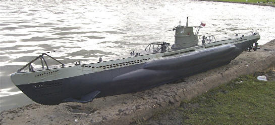
    I think this mother might actually become a decent model.

    The Boattrainman
    Last edited by The Boattrainman; 01-21-2018, 06:13 PM.
    ''We're after men, and I wish to God I was with them........!''

    Comment

    • HardRock
      Vice Admiral
      • Mar 2013
      • 1609

      #92
      Me too!!!!

      Comment

      • The Boattrainman
        Commander
        • Mar 2016
        • 443

        #93
        Both sets of railings are finished.......

        Click image for larger version

Name:	IMG_1446 (800x600).jpg
Views:	442
Size:	332.8 KB
ID:	124915


        .......and are trial fitted to the deck.............and the deck laid on the model.

        Click image for larger version

Name:	IMG_1449 (800x600).jpg
Views:	481
Size:	298.3 KB
ID:	124916


        Now beginning to look imposing.

        Click image for larger version

Name:	IMG_1448 (800x600).jpg
Views:	378
Size:	293.9 KB
ID:	124917


        And a size comparison with the 1/72 Skipkack 'USS Sculpin'.

        Click image for larger version

Name:	IMG_1451 (800x600).jpg
Views:	380
Size:	344.7 KB
ID:	124918


        The Boattrainman
        ''We're after men, and I wish to God I was with them........!''

        Comment

        • HardRock
          Vice Admiral
          • Mar 2013
          • 1609

          #94
          They really should have built those Skipjacks bigger you know. Must have been awfully cramped inside. (cue Derick Zoolander, "Is this a submarine for ants?")

          Comment

          • The Boattrainman
            Commander
            • Mar 2016
            • 443

            #95
            I'd hate to be trying to carry around a 1/40 scale Skipjack, would a be a beast!!!

            Rob
            ''We're after men, and I wish to God I was with them........!''

            Comment

            • The Boattrainman
              Commander
              • Mar 2016
              • 443

              #96
              To put the finishing touch to the central drainage slot, there are four circular supports, two each side.

              A 5mm tube is cut into four pieces........

              Click image for larger version

Name:	IMG_1453 (800x600).jpg
Views:	423
Size:	266.4 KB
ID:	124959


              .......four bar supports are removed............

              Click image for larger version

Name:	IMG_1454 (800x600).jpg
Views:	438
Size:	236.6 KB
ID:	124960


              ..............and the round pieces inserted in the vacant place.........

              Click image for larger version

Name:	IMG_1455 (800x600).jpg
Views:	441
Size:	219.6 KB
ID:	124961


              ...........and the view from the outside, one for the U-boat nerds, it's a small detail!

              Click image for larger version

Name:	IMG_1456 (800x600).jpg
Views:	457
Size:	206.4 KB
ID:	124962

              The Boattrainman
              ''We're after men, and I wish to God I was with them........!''

              Comment

              • The Boattrainman
                Commander
                • Mar 2016
                • 443

                #97
                Here are the brass masks from Boris, super detail made to 1/40 scale for this kit, made to order.He'll make all kinds of brass stuff to various scales to match the kits out there.

                Click image for larger version

Name:	IMG_1457 (800x600).jpg
Views:	460
Size:	308.8 KB
ID:	124964


                The rear set are stunning, but gonna be a bugger to fit.

                Click image for larger version

Name:	IMG_1458 (800x600).jpg
Views:	459
Size:	265.0 KB
ID:	124965


                The slots are drilled out for the forward pieces, the holes don't suit the replacement masks so they are fixed up with some styrene to support the new masks.

                Click image for larger version

Name:	IMG_1459 (800x600).jpg
Views:	423
Size:	243.2 KB
ID:	124966Click image for larger version

Name:	IMG_1460 (800x600).jpg
Views:	453
Size:	232.2 KB
ID:	124967


                The masks are rolled with a brass bar to get them slightly curved, I also rounded off the sharp corners

                Click image for larger version

Name:	IMG_1461 (800x600).jpg
Views:	412
Size:	307.9 KB
ID:	124968


                Because they are just 0.3mm thick they are just stuck onto the hull, so a dremel and grinding stone is used to feather the edges, getting them down to 0.1mm.

                Click image for larger version

Name:	IMG_1462 (600x800).jpg
Views:	433
Size:	261.4 KB
ID:	124970


                The rest will be done with filler and sandpaper, this was easy, giving me confidence to tackle the rear set.

                Click image for larger version

Name:	IMG_1463 (800x600).jpg
Views:	437
Size:	271.0 KB
ID:	124969Click image for larger version

Name:	IMG_1464 (800x600).jpg
Views:	475
Size:	270.4 KB
ID:	124971


                The Boattrainman

                ''We're after men, and I wish to God I was with them........!''

                Comment

                • The Boattrainman
                  Commander
                  • Mar 2016
                  • 443

                  #98
                  The rear sets present a whole different challenge, the complex curves and you can't remove a large section of the hull as this will weaken a critical area.

                  So, to start the rear sets a re cut up into smaller pieces and fixed to the hull.

                  Click image for larger version

Name:	IMG_1465 (800x600).jpg
Views:	450
Size:	253.9 KB
ID:	125004


                  Then the plastic behind is drilled out with a 1mm drill bit in a Dremel.

                  Click image for larger version

Name:	IMG_1466 (800x600).jpg
Views:	428
Size:	263.6 KB
ID:	125005


                  This is the inside.

                  Click image for larger version

Name:	IMG_1467 (600x800).jpg
Views:	454
Size:	248.5 KB
ID:	125007


                  Not quite as difficult as first thought but still a full days work to get this far.

                  Click image for larger version

Name:	IMG_1468 (800x600).jpg
Views:	426
Size:	238.9 KB
ID:	125006


                  The Boattrainman

                  ''We're after men, and I wish to God I was with them........!''

                  Comment

                  • The Boattrainman
                    Commander
                    • Mar 2016
                    • 443

                    #99
                    The final flood/drain holes are added using the brass plates as a mask, stuck down with tape and drilled out with my Dremel tool.


                    Click image for larger version

Name:	IMG_1472 (800x600).jpg
Views:	464
Size:	239.1 KB
ID:	125069Click image for larger version

Name:	IMG_1473 (800x600).jpg
Views:	436
Size:	252.6 KB
ID:	125070


                    It's over, the flood/drain holes are finished, what a pain in the a** to do!!!


                    One thing kept bothering me as I worked on the rear section, I never noticed it before, but the rudders are way too big.

                    So 5mm was cut off the bottom and 8mm off the ends.

                    Click image for larger version

Name:	IMG_1475 (800x600).jpg
Views:	431
Size:	275.9 KB
ID:	125071Click image for larger version

Name:	IMG_1476 (800x600).jpg
Views:	420
Size:	285.4 KB
ID:	125072


                    This removed the locating pin for the rudder support, I added new pins from 2.5mm brass rod, into holes in line with tiller arm

                    Click image for larger version

Name:	IMG_1477 (800x600).jpg
Views:	466
Size:	245.8 KB
ID:	125073


                    Better if not perfect, but there is still that horrible knuckle over the rudders that's not on the original. Sort that later.

                    The Boattrainman


                    ''We're after men, and I wish to God I was with them........!''

                    Comment

                    • MFR1964
                      Detail Nut of the First Order
                      • Sep 2010
                      • 1304

                      I read all through your thread, i admire you for taking the challence to turn the Robbe kit into a decent type VII, yes, those floodholes drive you mad i've had the same road to travel, you where lucky to get a nice deck, i had to make mine from scratch, took me two winters to finish it.
                      I own a type VII also, scale 1:35, making it a big six footer, i keep my eyes on you, keep up the good work.

                      Manfred.
                      I went underground

                      Comment

                      • The Boattrainman
                        Commander
                        • Mar 2016
                        • 443

                        Hi Manfred,

                        Thanks for the comments, would love to see pics of your Type VII, especially if it's from the Robbe kit.

                        My hat is off to you if you scratchbuilt the deck, what a nightmare, I notice even the Engel Type VII kit now has the holes predrilled (for €2,999!!!!), I really wouldn't have the patience.

                        Seven months on, and I still haven't looked at any of the internals yet, hope to start some the electronics before the summer.

                        Rob

                        ''We're after men, and I wish to God I was with them........!''

                        Comment

                        • MFR1964
                          Detail Nut of the First Order
                          • Sep 2010
                          • 1304

                          Rob,

                          The type VII i own is not the Robbe kit but scratchbuild from factorydrawings.
                          I'll digg up some pics for you, i must say i've sold her a few years ago and got me another type VII at the same scale, but she is a differend story.
                          Seven months, calculate a year total before you can start with the electrical stuff.

                          Manfred.
                          I went underground

                          Comment

                          • MFR1964
                            Detail Nut of the First Order
                            • Sep 2010
                            • 1304

                            Totally offtopic since this is not a Robbe kit, but you get the impression when you've finished your boat.

                            Click image for larger version

Name:	IMG_0985.JPG
Views:	340
Size:	9.1 KB
ID:	125081

                            Click image for larger version

Name:	IMG_0986.JPG
Views:	323
Size:	8.4 KB
ID:	125082

                            Click image for larger version

Name:	IMG_0987.JPG
Views:	324
Size:	8.6 KB
ID:	125083

                            This boat was build as a Type VII/41, main difference between the early boats and this one is, most parts of this boat where welded instead of using rivets all the way, the one at the back is my present boat, it belonged to my good friend and teacher, it took some months to get it back into working order.


                            Manfred.
                            I went underground

                            Comment

                            • The Boattrainman
                              Commander
                              • Mar 2016
                              • 443

                              Thanks Manfred, great photos, not sure if mine will measure up to your standard.

                              Just to test my method I put some of the horizontal support bars in place, using 2mm x 0.5mm styrene and wide masking tape for a straight edge.

                              Click image for larger version

Name:	IMG_1478 (800x600).jpg
Views:	428
Size:	261.0 KB
ID:	125093Click image for larger version

Name:	IMG_1479 (800x600).jpg
Views:	425
Size:	242.8 KB
ID:	125094


                              Now I can position the two 'bumps' on either side (vents for the Torp tubes perhaps?). I cut four diagonal pieces from 4mm styrene tube.

                              Click image for larger version

Name:	IMG_1480 (800x600).jpg
Views:	387
Size:	272.4 KB
ID:	125095Click image for larger version

Name:	IMG_1481 (800x600).jpg
Views:	393
Size:	229.3 KB
ID:	125096

                              Click image for larger version

Name:	IMG_1482 (800x600).jpg
Views:	393
Size:	256.2 KB
ID:	125097


                              Then the UT(4 each side) and GHG sensors(15 each side), from pieces of the same styrene 4mm tube and some 3mm rod.

                              Click image for larger version

Name:	IMG_1484 (800x600).jpg
Views:	418
Size:	283.0 KB
ID:	125098Click image for larger version

Name:	IMG_1485 (800x600).jpg
Views:	383
Size:	235.9 KB
ID:	125099


                              To add some definition to the UT sensors the tips of microswitch covers are removed and stuck in the centres.

                              Click image for larger version

Name:	IMG_1488 (800x600).jpg
Views:	407
Size:	250.2 KB
ID:	125100Click image for larger version

Name:	IMG_1489 (800x600).jpg
Views:	375
Size:	243.6 KB
ID:	125101


                              The whole lot are hard sanded back to the hull leaving only around 1mm proud.

                              Click image for larger version

Name:	IMG_1490 (800x600).jpg
Views:	411
Size:	249.8 KB
ID:	125102


                              The Boatrainman


                              ''We're after men, and I wish to God I was with them........!''

                              Comment

                              • MFR1964
                                Detail Nut of the First Order
                                • Sep 2010
                                • 1304

                                Rob,

                                I've got me no standard just a slight disorder for details, you're doing good work at your boat.
                                Those humps are indeed the vents for the tubes, only present outside at the early boats, later on they where hidden inside the non-pressure hull.

                                Manfred.
                                I went underground

                                Comment

                                Working...