A Skipjack in Ireland

Collapse
X
 
  • Time
  • Show
Clear All
new posts
  • The Boattrainman
    Commander
    • Mar 2016
    • 443

    #91
    The sail has had all the holes opened to take the Photoetched parts. I'm just using the larger PE parts as the smaller ones are tiny.

    Click image for larger version

Name:	IMG_0593 (800x600).jpg
Views:	211
Size:	35.4 KB
ID:	114059


    The sail with the PE parts attached in the pre-drilled holes which have a backing of 0.5mm Plasticard and the hole filled with 1mm card and then the PE glued into the recess.

    Click image for larger version

Name:	IMG_0594 (800x600).jpg
Views:	183
Size:	36.6 KB
ID:	114060


    To be honest, apart from the vents on both sail sides which match my hull gratings nicely, I'm not sure the PE parts will add that much to a R/C model given the viewing distance, perhaps a super-detailed static model will benefit more, given this detail work took over a week of drilling, sanding and fettling.

    That said, there are superb parts for the port/starboard sail lights and the radar on the PE fret which could not be produced any other way.

    The Boattrainman

    Last edited by The Boattrainman; 05-01-2016, 12:52 PM.
    ''We're after men, and I wish to God I was with them........!''

    Comment

    • The Boattrainman
      Commander
      • Mar 2016
      • 443

      #92

      A final test of all the running lights is done, the wiring is led through the various guides and the sail sides and top united. An old model train controller is used to replicate the 12V running battery.

      Click image for larger version

Name:	IMG_0595 (800x600).jpg
Views:	232
Size:	34.4 KB
ID:	114063 Click image for larger version

Name:	IMG_0600 (800x600).jpg
Views:	207
Size:	39.1 KB
ID:	114062


      I'm giving some consideration to the mast light being a 'nano' LED, but I'm quite happy with the lights at this stage.

      Click image for larger version

Name:	IMG_0596 (800x600).jpg
Views:	200
Size:	39.0 KB
ID:	114064 Click image for larger version

Name:	IMG_0597 (800x600).jpg
Views:	192
Size:	39.3 KB
ID:	114065


      Time for some Primer, I find this is the only way to identify and rectify surface blemishes, of which there already many.

      The Boattrainman


      Last edited by The Boattrainman; 05-01-2016, 03:39 PM.
      ''We're after men, and I wish to God I was with them........!''

      Comment

      • trout
        Admiral
        • Jul 2011
        • 3549

        #93
        Well done lighting!
        If you can cut, drill, saw, hit things and swear a lot, you're well on the way to building a working model sub.

        Comment

        • The Boattrainman
          Commander
          • Mar 2016
          • 443

          #94
          So some good and bad news with the first of many Primer coats, which will be done with acrylic spray cans (Humbrol range).

          Click image for larger version

Name:	IMG_0601 (800x600).jpg
Views:	201
Size:	37.1 KB
ID:	114091


          The main seams have come out quite well and will need just a small amount of work, there's a seam running top to bottom here, nearly invisible.

          Click image for larger version

Name:	IMG_0608 (800x600).jpg
Views:	199
Size:	32.1 KB
ID:	114094


          The Photoetched hatches and ballast vents add nicely to the main deck.

          Click image for larger version

Name:	IMG_0609 (800x600).jpg
Views:	199
Size:	32.9 KB
ID:	114092 Click image for larger version

Name:	IMG_0610 (800x600).jpg
Views:	191
Size:	34.0 KB
ID:	114093


          The scratchbuilt inlet gratings look reasonable now they have blended in.

          Click image for larger version

Name:	IMG_0606 (800x600).jpg
Views:	213
Size:	35.2 KB
ID:	114095


          However, there is a serious problem with the nose! As well as the obvious line where the two halves meet which can be filled, there is a dip along this seam resulting in the rounded shape having a flat in it around the entire nose, plus (to my eyes) the nose is slightly an odd shape, with the most forward part having a slight bulge outwards again spoiling the teardrop shape. It's not a biggy, but it will need some work to get it properly 'rounded', but it's the only flaw in what has been an excellent kit so far.

          As for the flat meeting of the two halves, I can't see any solution other than some serious filling/sanding.


          Click image for larger version

Name:	IMG_0605 (800x600).jpg
Views:	194
Size:	35.9 KB
ID:	114096

          If you enlarge the picture up a bit, you can clearly see a flat spot to the left of the torpedo doors at the seam.

          The Boattrainman
          Last edited by The Boattrainman; 05-03-2016, 05:27 PM.
          ''We're after men, and I wish to God I was with them........!''

          Comment

          • The Boattrainman
            Commander
            • Mar 2016
            • 443

            #95
            To try to solve the flat line around the seam, I've stuck a double thickness line of masking tape either side of the seam one on top of the other, and filled the gap with filler. When the tapes are removed this leaves a ridge of filler.


            Click image for larger version

Name:	image_31953.jpg
Views:	221
Size:	37.9 KB
ID:	114100 Click image for larger version

Name:	image_31954.jpg
Views:	203
Size:	33.7 KB
ID:	114101


            This ridge is sanded into the hull but the centre is left alone reinstating the curve, plus I have hard sanded the top of the nose back to get the shape totally symmetrical.

            Click image for larger version

Name:	IMG_0614 (800x600).jpg
Views:	188
Size:	30.4 KB
ID:	114102


            Because I hard sanded the nose, I lost definition of the scribed lines for the torpedo doors, I had to re-scribe the centre ones (they are a bit rough in the photo, I'll fine sand etc. later).

            Click image for larger version

Name:	IMG_0616 (800x600).jpg
Views:	205
Size:	35.2 KB
ID:	114103


            The nose (in my humble opinion) is still not 'perfect' in terms of shape, but I can live with it now.

            The Boattrainman
            Last edited by The Boattrainman; 05-03-2016, 03:56 PM.
            ''We're after men, and I wish to God I was with them........!''

            Comment

            • The Boattrainman
              Commander
              • Mar 2016
              • 443

              #96

              The main hull is now blemish free, the access door and other parts will now be 'primed'.

              Click image for larger version

Name:	IMG_0617 (800x600).jpg
Views:	193
Size:	34.6 KB
ID:	114124


              There was a lot of work to fair the large vents into the hull.

              Click image for larger version

Name:	IMG_0618 (800x600).jpg
Views:	190
Size:	30.5 KB
ID:	114125


              The main hull is now blemish free, it took three evenings work.

              Click image for larger version

Name:	IMG_0620 (800x600).jpg
Views:	187
Size:	36.8 KB
ID:	114126


              The Boattrainman
              ''We're after men, and I wish to God I was with them........!''

              Comment

              • The Boattrainman
                Commander
                • Mar 2016
                • 443

                #97
                Occasionally you come across a blemish in a horrendous location. This nick around 2mm wide was in one of the rear dive planes, filler won't work here as the insertion of the dive plane axle will eventually destroy such a repair.

                Click image for larger version

Name:	IMG_0623 (800x600).jpg
Views:	212
Size:	33.4 KB
ID:	114140 Click image for larger version

Name:	IMG_0624 (800x600).jpg
Views:	203
Size:	33.3 KB
ID:	114141


                To fix it, the nick was filed out to a roughly square shape and using a scrap metal bar inserted in the axle hole as a backing, a small fillet of Plasticard loaded with thick Superglue is inserted into the enlarged hole. The metal bar is pulled down the hole before the glue sets, leaving the fillet intact.

                Click image for larger version

Name:	IMG_0626 (800x600).jpg
Views:	190
Size:	35.9 KB
ID:	114142 Click image for larger version

Name:	IMG_0627 (800x600).jpg
Views:	186
Size:	35.2 KB
ID:	114143


                The fillet is carefully cut back, and before final sanding a small amount of very thin Superglue spread around it and then sanded back to the shape of the plane.

                Click image for larger version

Name:	IMG_0628 (800x600).jpg
Views:	203
Size:	33.4 KB
ID:	114144 Click image for larger version

Name:	IMG_0629 (800x600).jpg
Views:	191
Size:	34.9 KB
ID:	114145


                Once primed, the repair is invisible.

                The Boattrainman

                Last edited by The Boattrainman; 05-06-2016, 04:34 PM.
                ''We're after men, and I wish to God I was with them........!''

                Comment

                • The Boattrainman
                  Commander
                  • Mar 2016
                  • 443

                  #98
                  There is a great story about Vic Green, one of the greatest professional Model Locomotive builders ever, his 1/35 Scale British locos go for many tens of thousands of pounds and were only available to 'rich' clients with large cheque books.

                  When questioned about the high cost of each item, he explained that as well as the hours needed to construct the models from scratch (which if billed by the hour would mean the items would be even beyond the well resourced), he rejected about two-thirds of his work as not up to standard, I think in his career he built under 50 locomotives. One of his masterworks is below.

                  Click image for larger version

Name:	9f%20vg[1].jpg
Views:	89
Size:	11.2 KB
ID:	114176


                  While I'm not in Vic's lofty league, I've decided the sail is just not good enough. The difference between the vents/access hatches using the Photoetched parts and original Revell scribed ones are too different, leading to an inconsistent look. One of the key aspects of any model is that the overall model must look like similar techniques were used for the end result, and as it stands this is not the case with my sail.

                  Click image for larger version

Name:	IMG_0632 (800x600).jpg
Views:	186
Size:	34.6 KB
ID:	114177


                  So this will have to go in the bin.

                  The Boattrainman
                  Last edited by The Boattrainman; 05-08-2016, 07:52 AM.
                  ''We're after men, and I wish to God I was with them........!''

                  Comment

                  • The Boattrainman
                    Commander
                    • Mar 2016
                    • 443

                    #99
                    Here is the second attempt at the Caswell sail plane linkage/yoke, a process I should have undertaken the first time.

                    Squares and a ruler are used to measure the distance between the axle centres which is 24mm for a tight fit of the teeth in the units. The distance is drawn on to two 12mm wide pieces of 0.5mm Plasticard.


                    Click image for larger version

Name:	image_32005.jpg
Views:	188
Size:	36.6 KB
ID:	114231 Click image for larger version

Name:	image_32006.jpg
Views:	204
Size:	34.3 KB
ID:	114232


                    Once drilled for both the sail plane arms and the yoke axle the parts have two square pieces of 2mm card glued to the bottom of the new fitting where the yoke axle will fit. It is opened out to the axle diameter and then a trial fit of the parts is undertaken


                    Click image for larger version

Name:	IMG_0636 (800x600).jpg
Views:	177
Size:	33.9 KB
ID:	114233 Click image for larger version

Name:	IMG_0638 (800x600).jpg
Views:	179
Size:	36.0 KB
ID:	114234


                    This little mechanism sets the distance between yoke and sailplane cog, no matter how you set them they will always be at the correct distance and perfectly interlocked.


                    Click image for larger version

Name:	IMG_0639 (800x600).jpg
Views:	166
Size:	34.8 KB
ID:	114235 Click image for larger version

Name:	IMG_0642 (800x600).jpg
Views:	147
Size:	36.4 KB
ID:	114236


                    The new parts are stuck to each side of the new sail planes I acquired from another kit, the straight lines help to keep it all in line. The sail plane hole is made to align with the top hole of the new fitting, if you have the Caswell resin bushes they can be pushed into the hole from the outside, mine are gone on version one, but it doesn't matter the Plasticard is strong enough to act as an axle bearer.

                    The Boattrainman
                    Last edited by The Boattrainman; 05-10-2016, 03:51 PM.
                    ''We're after men, and I wish to God I was with them........!''

                    Comment

                    • The Boattrainman
                      Commander
                      • Mar 2016
                      • 443

                      The throw extender is shortened and a servo arm connector is attached to further move the attachment point away from centre. A number of L-shaped pieces of Plasticard are cut to 10mm width and a hole to take the 'snake' pushrod drilled in each.


                      Click image for larger version

Name:	IMG_0643 (800x600).jpg
Views:	178
Size:	35.9 KB
ID:	114260 Click image for larger version

Name:	IMG_0644 (800x600).jpg
Views:	170
Size:	33.8 KB
ID:	114261


                      The 'snake' is fed through the holes and the inner sleeve inserted in the pushrod connector, I've cut away sections of the inner hull bracing to allow the snake pass plus moved it further toport to connect with the lever mechanism I made to attach to this pushrod and the sail plane servo pushrod exiting the Subdriver.


                      Click image for larger version

Name:	IMG_0645 (800x600).jpg
Views:	164
Size:	36.7 KB
ID:	114262 Click image for larger version

Name:	IMG_0646 (800x600).jpg
Views:	168
Size:	36.8 KB
ID:	114263


                      The Boattrainman
                      Last edited by The Boattrainman; 05-12-2016, 02:25 PM.
                      ''We're after men, and I wish to God I was with them........!''

                      Comment

                      • The Boattrainman
                        Commander
                        • Mar 2016
                        • 443

                        The new sail means I can re-visit the wiring, so I've gone for something different to last time, just one + and one - existing the sail.

                        Click image for larger version

Name:	IMG_0647 (800x600).jpg
Views:	143
Size:	34.3 KB
ID:	114304


                        The side lights get a plastic surround again.

                        Click image for larger version

Name:	IMG_0648 (800x600).jpg
Views:	161
Size:	36.9 KB
ID:	114305


                        They are filled with epoxy to completely enclose the wiring and resistors.

                        Click image for larger version

Name:	IMG_0649 (800x600).jpg
Views:	159
Size:	35.8 KB
ID:	114303


                        A bit neater than six wires to deal with, I'll close the sail later but work out a wiring route in the main hull next.
                        Last edited by The Boattrainman; 05-14-2016, 03:47 PM.
                        ''We're after men, and I wish to God I was with them........!''

                        Comment

                        • The Boattrainman
                          Commander
                          • Mar 2016
                          • 443

                          The new sail sides are united and primed.

                          Click image for larger version

Name:	IMG_0651 (800x600).jpg
Views:	160
Size:	35.3 KB
ID:	114422


                          The sail top is not glued on yet, I want to see the snorkel operating correctly when installed, I understand there is a Mark 2 Snorkel with the 3.5''Subdriver.

                          Click image for larger version

Name:	IMG_0652 (800x600).jpg
Views:	163
Size:	35.3 KB
ID:	114420


                          There is still plenty of minor filling and sanding to do.

                          Click image for larger version

Name:	IMG_0650 (800x600).jpg
Views:	183
Size:	38.6 KB
ID:	114421


                          On to the wiring route inside the hull.

                          The Boattrainman


                          Last edited by The Boattrainman; 05-22-2016, 03:29 PM.
                          ''We're after men, and I wish to God I was with them........!''

                          Comment

                          • He Who Shall Not Be Named
                            Moderator
                            • Aug 2008
                            • 12375


                            Your comment as to there being a, ‘MK-2 Snorkel’ provided with the 3.5 SD may originate with an earlier post where I described the ‘horizontal’ type snorkel mechanism I developed for use in the smaller 1/96 SKIPJACK kits I produce. As that sized sail is too narrow to provide for a proper float I was compelled to go with this arrangement – that took advantage of the wider base of the sail. However, this mechanism is not to be confused with the ‘vertical’ snorkel mechanism employed (and provide with the 3.5 SD) by the 1/72 SKIPJACK.


                            J
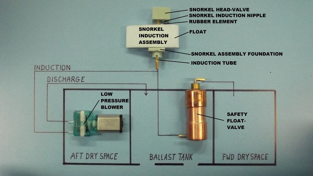
                            ust a little refresher on how the SemiASpirated ballast sub-system works. Air to blow the ballast tank is either scavenged out of the SD’s air-spaces or from atmosphere from the open snorkel head-valve. The examples here show the safety float-valve with the external plumbing, the 3.5’s unit is housed within the after dry space and has no external plumbing.


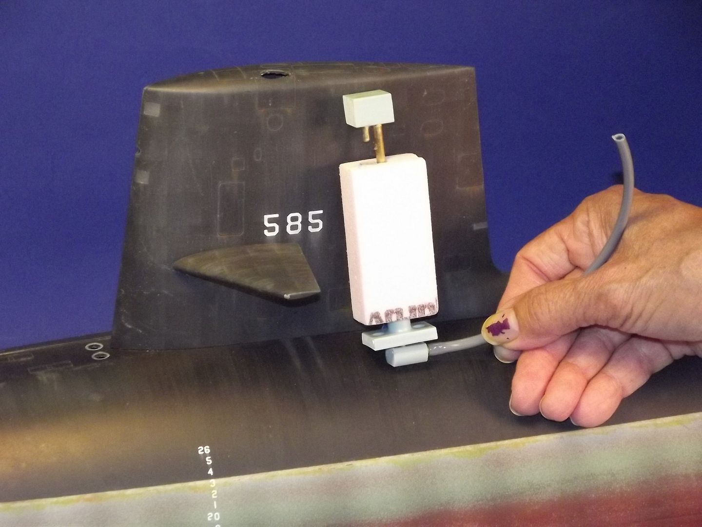
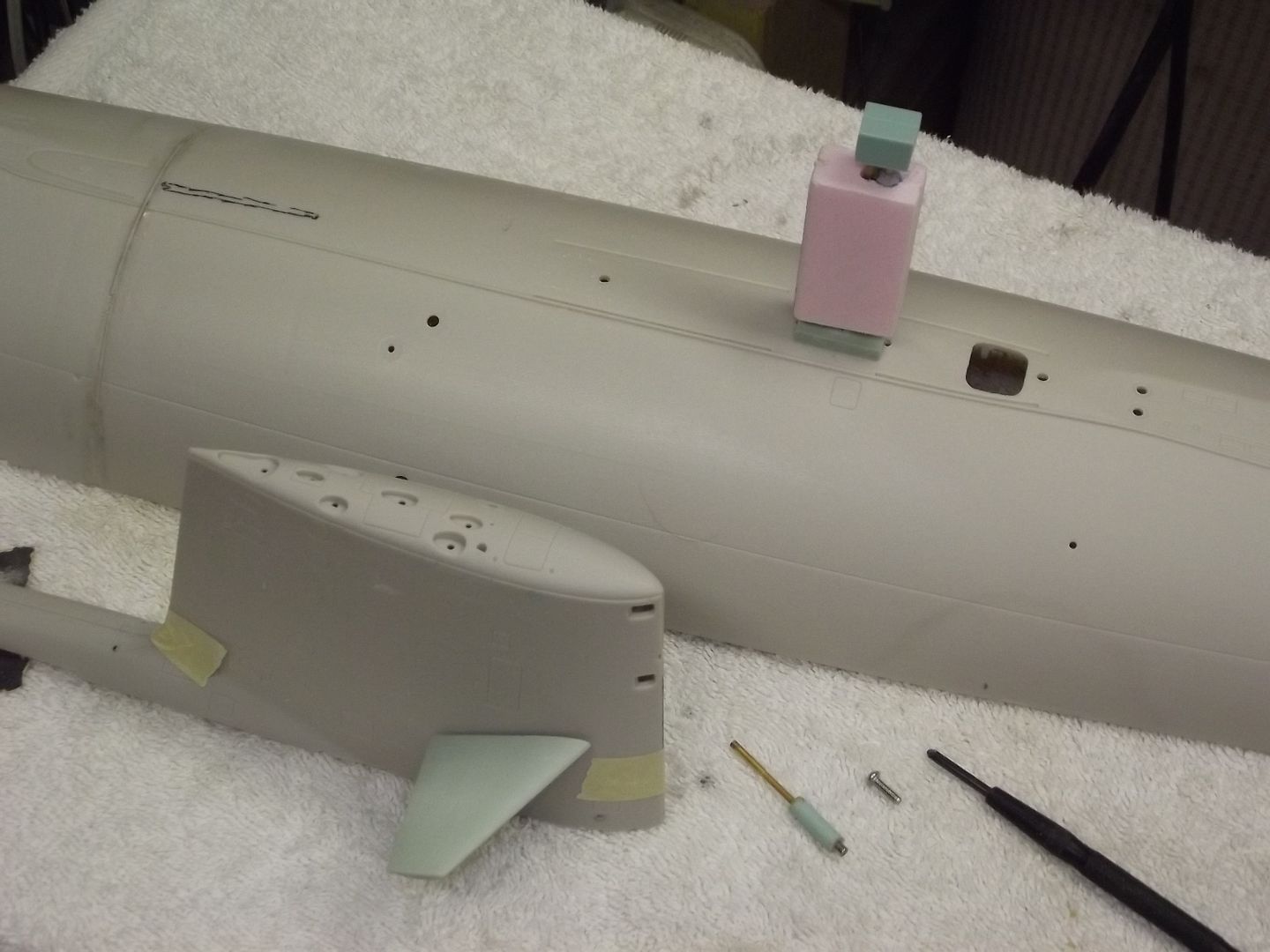
                            Typical of the ‘vertical’ type snorkel mechanism provided with the 3.5 SD. It fits comfortably within the 1/72 SKIPJACK sail.


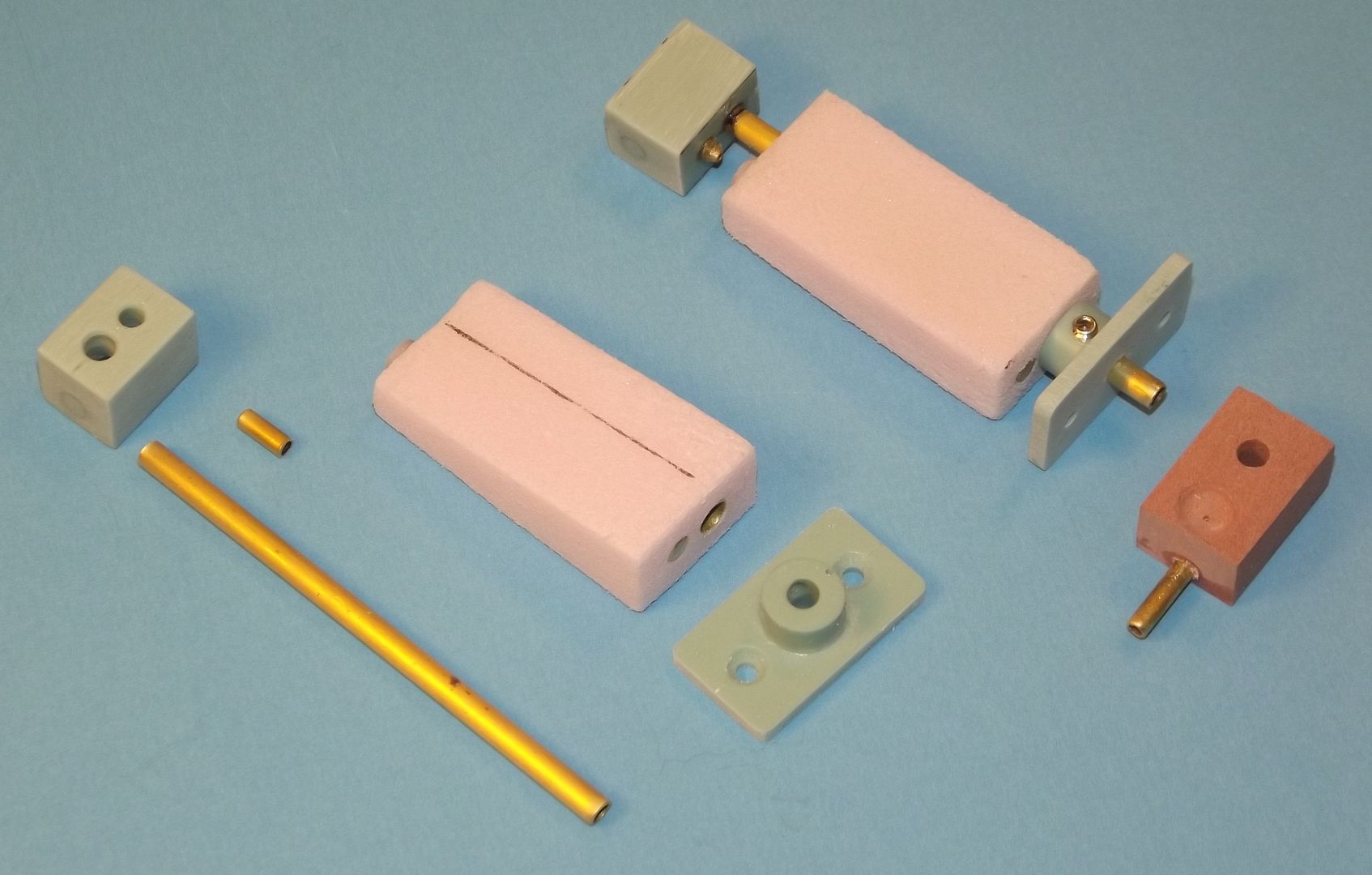
                            Break-down of a typical ‘vertical’ type snorkel mechanism – there are slight differences for different scales and types of r/c submarine sails these things have to fit into.

                            Who is John Galt?

                            Comment

                            • The Boattrainman
                              Commander
                              • Mar 2016
                              • 443

                              Thanks David for the info on the snorkel assembly, much appreciated

                              To lead the sail lights wiring to the connection point at the rear of the sub, I've made some 3cm long wire guides from 7mm square Plasticard, each with three 4mm holes drilled so air and water won't get trapped in them.


                              Click image for larger version

Name:	IMG_0653 (800x600).jpg
Views:	156
Size:	33.4 KB
ID:	114621 Click image for larger version

Name:	IMG_0654 (800x600).jpg
Views:	168
Size:	32.2 KB
ID:	114622


                              They are glued to the hull on the opposite side from the sail plane 'snake', and a loop of wire will be left so the sail can be lifted off for maintenance.

                              Click image for larger version

Name:	IMG_0655 (800x600).jpg
Views:	161
Size:	34.8 KB
ID:	114623


                              The wiring will go to the rear of the sub to unite with the rear light wiring.

                              Click image for larger version

Name:	IMG_0656 (800x600).jpg
Views:	184
Size:	38.5 KB
ID:	114624


                              The Boattrainman
                              Last edited by The Boattrainman; 05-29-2016, 11:00 AM.
                              ''We're after men, and I wish to God I was with them........!''

                              Comment

                              • Tugfan
                                Lieutenant Commander
                                • Nov 2010
                                • 178

                                More! More!

                                Comment

                                Working...