Tool time.

Collapse
X
 
  • Time
  • Show
Clear All
new posts

  • He Who Shall Not Be Named
    replied
    Originally posted by Davidh
    Hello David and all,

    Thanks for the advice on the last questions regarding molds for the sail/ conning tower. I have created the molds for this and the parts have turned out well. My next question is regarding the main hull which I am almost at the stage of creating all the molds for. I intend on doing a seven part mold. Yes, seven. The reason is that the hull unlike my usual Soviet boats ain’t simple.

    The stern and the bow sections have some really intricate undercuts and design features that mean I need molds that will need to be removed at various angles. It will also be a hybrid mold, the stern and bow section will be silicon glove/ hard shell and the middle will be a glass hard shell mould spilt down the axis to make the box keel easier to deal with. I have some drawings of what I intend to do and would like your feedback if possible. I would be able to mold the bow and stern sections individually or bolt them onto the middle section and layup in one go. Will there be expansions and contraction problems with the two different types of molds combined?
    Are there any other issues that your experience tells you I need to be aware of?

    Anyway, if you could look at the drawings and tell me what you think..

    Click image for larger version

Name:	07615CB7-9343-4B14-8887-00C2AAD3A1B1.jpeg
Views:	387
Size:	86.7 KB
ID:	153371Click image for larger version

Name:	315945BD-D62B-47BB-B45C-EB1BB3E19D58.jpeg
Views:	377
Size:	85.2 KB
ID:	153372
    David,

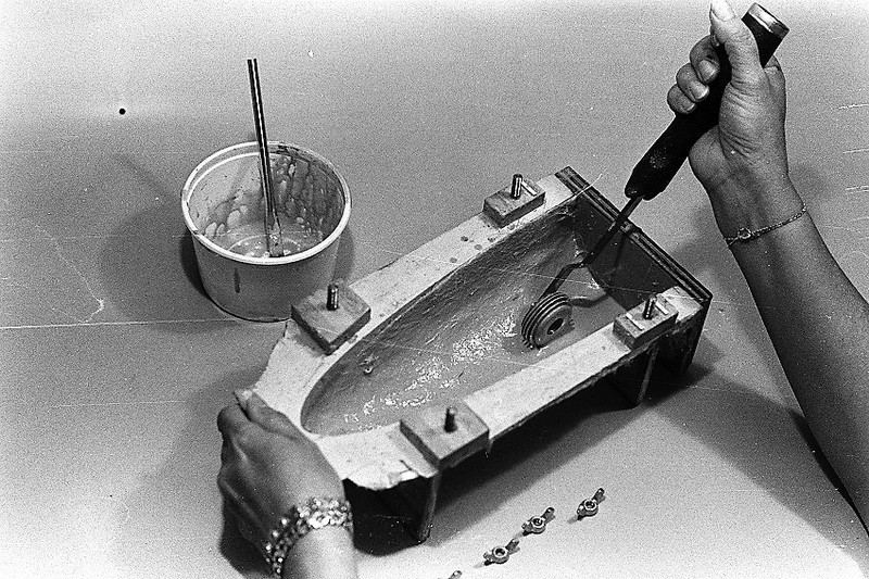
    First off, I apologize for the poor quality black-and-white photography here. Ellie and I chronicled this work over 35 years ago when I was doing my own photo lab work to save a few dimes.

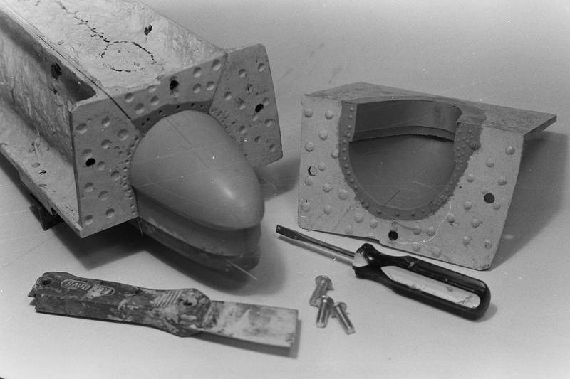
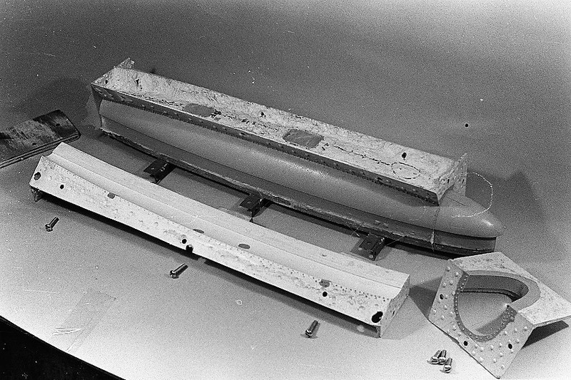
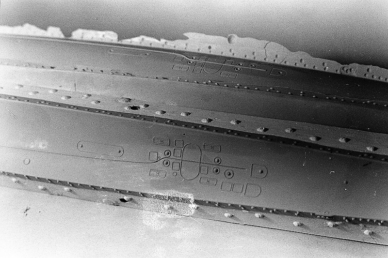
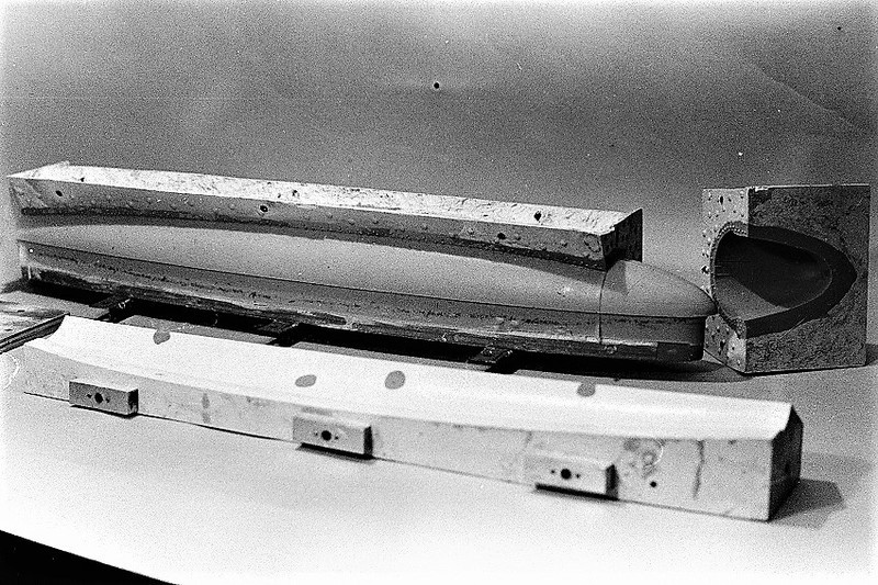
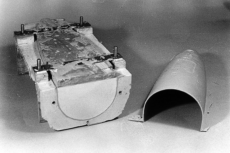
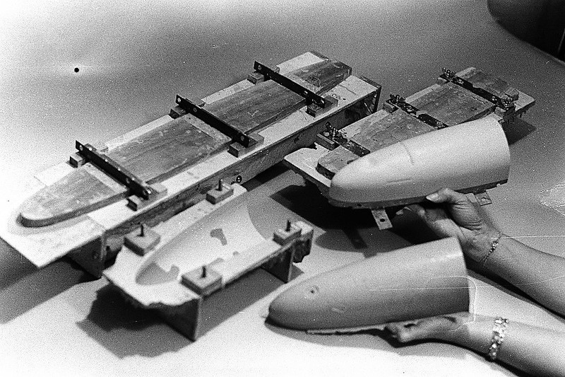
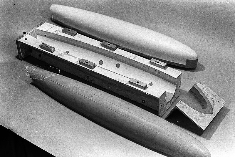
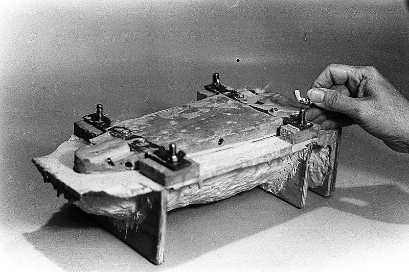
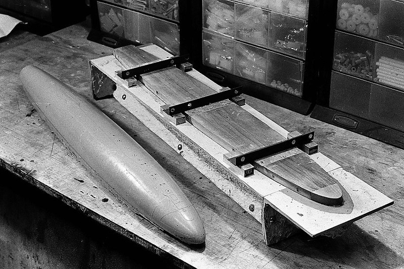
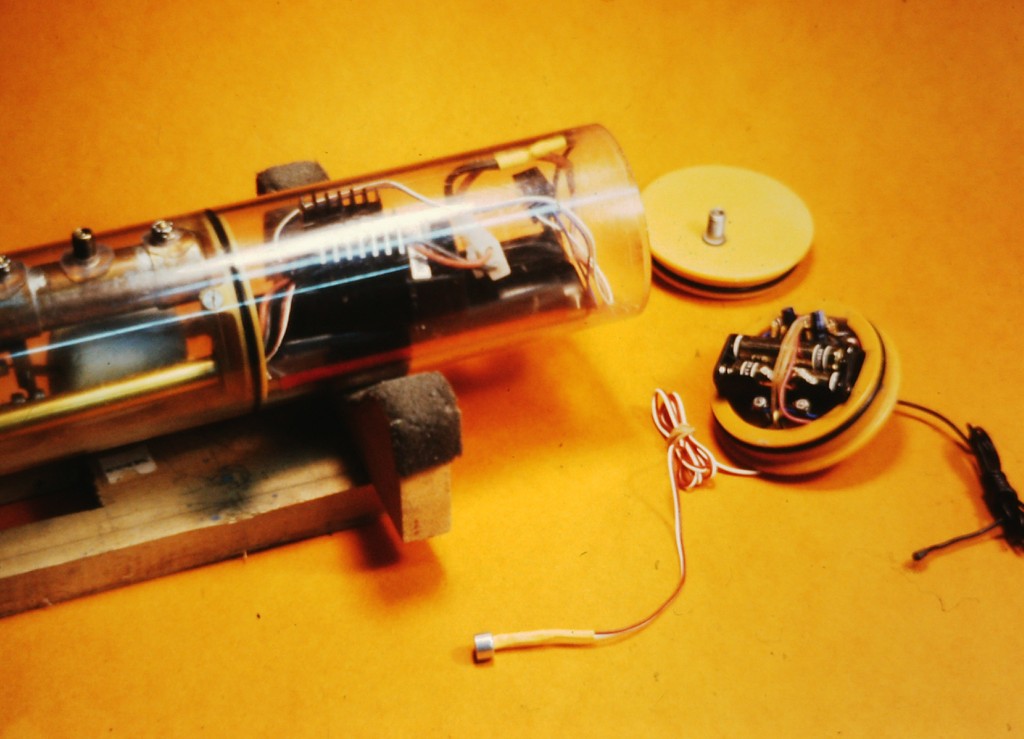
    What you see here are three of the eventual five iterations of highbred tooling we produced to manufacture thin walled 1/96 SKIPJACK hull parts for our first commercially available kit. As confusing as some of this may be you will see that our work, very closely, follows your shop-sketches of your proposed tool making methodology: multi-piece tools comprising both hard-shell, and rubber glove surfaces.

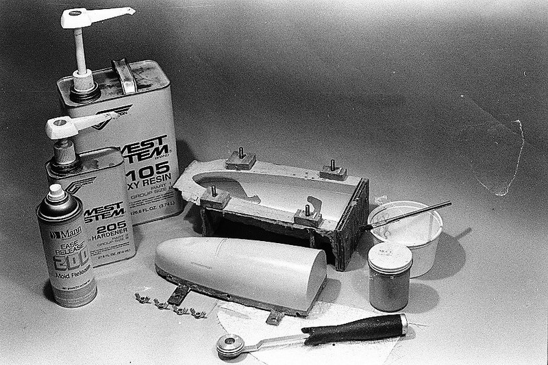
    Also note that we incorporated a 'displacing plug' to form the inside of the hull pieces as well. This item not only set a specific wall thickness, but also permitted us to only one glass-resin lay-up operation to produce a GRP hull part. Only complication to that was the necessity of pressurizing the entire assembly to two atmospheres during the curing process.

    You examine the photos and if any specific questions as to process come to mind address them here and I'll take them on, point by point.

    I so enjoy watching you embrace these techniques and processes, David.


    Leave a comment:


  • Davidh
    replied
    Hello David and all,

    Thanks for the advice on the last questions regarding molds for the sail/ conning tower. I have created the molds for this and the parts have turned out well. My next question is regarding the main hull which I am almost at the stage of creating all the molds for. I intend on doing a seven part mold. Yes, seven. The reason is that the hull unlike my usual Soviet boats ain’t simple.

    The stern and the bow sections have some really intricate undercuts and design features that mean I need molds that will need to be removed at various angles. It will also be a hybrid mold, the stern and bow section will be silicon glove/ hard shell and the middle will be a glass hard shell mould spilt down the axis to make the box keel easier to deal with. I have some drawings of what I intend to do and would like your feedback if possible. I would be able to mold the bow and stern sections individually or bolt them onto the middle section and layup in one go. Will there be expansions and contraction problems with the two different types of molds combined?
    Are there any other issues that your experience tells you I need to be aware of?

    Anyway, if you could look at the drawings and tell me what you think..

    Click image for larger version

Name:	07615CB7-9343-4B14-8887-00C2AAD3A1B1.jpeg
Views:	387
Size:	86.7 KB
ID:	153371Click image for larger version

Name:	315945BD-D62B-47BB-B45C-EB1BB3E19D58.jpeg
Views:	377
Size:	85.2 KB
ID:	153372

    Leave a comment:


  • Davidh
    replied
    Thankyou David.

    Leave a comment:


  • He Who Shall Not Be Named
    replied
    As to the proposed sail tool: Good sound design. Go with it.

    As to the thickness of the rubber between flask wall and pattern side surfaces. Rule-of-thumb is 1.5 times the minimum width. Assuming your sail is 1" thick, then the inside of the flask would measure 4". For the length, figure 1" in front, and 1" in back. Say your sail is 8" long, then the length of the flask, on the inside, would be 10". And allow 1" of rubber over the top and bottom of the sail master.

    Us displacing blocks to minimize the amount of rubber needed, like this:

    Click image for larger version  Name:	DSCF0083.JPG Views:	0 Size:	66.7 KB ID:	152256Click image for larger version  Name:	DSCF0085.JPG Views:	0 Size:	66.2 KB ID:	152257

    And use the flask as your strong-back during resin casting:

    Click image for larger version  Name:	DSCF7704.JPG Views:	0 Size:	63.9 KB ID:	152258Click image for larger version  Name:	IMG_0726.JPG Views:	0 Size:	57.4 KB ID:	152259

    As to the very thin sectioned canvas shield: When you make the pour first subject the tool (and the resin within) to a hard vacuum to force out all the air that inevitably got trapped in the narrow tool cavities. Then quickly pressurize the work to at least one-atmosphere and let it stay there till the resin cures hard. Provide 'frothing' extensions to your sprue and vent network so you don't make a god-awful mess when pulling the vacuum.

    David
    Last edited by He Who Shall Not Be Named; 08-09-2021, 10:59 PM.

    Leave a comment:


  • Davidh
    replied
    Hello all,

    David, this ones for you..

    I have been looking very closely at your section in today's work on the creation of the molds for the fin of the Blueback. I have decided to create molds in just the same way for the main conning tower section of my upcoming U-23 class. I just have a couple of questions for you regarding this procedure and how i should apply it to what I am doing.


    I intend on inverting the main conning tower section that I wish to mold. It is a through piece with the deck of the conning tower molded as a separate piece I will have a thin boundary inside the main cavity in the middle to create a barrier between the top and bottom halves of the mold. I don't intend on splitting the molds down the side. So there will be a base and an insert. Here is a pic of the part i am going to mold and base beneath.

    Click image for larger version

Name:	IMG-6425.JPG
Views:	233
Size:	70.4 KB
ID:	152153

    I though I would include these sketches as they may help explain what i am trying to. My main question is with regards to wall thickness. How thick should I make the wall around the side and also the end of the mold. Do you cast the part inside the original wooden box scaffold that you made or is your rubber mold thick enough. ( You have split the mold down the side, could you still use rubber bands and blocks? I am not quite sure. Is the base shown above a bit too thick?

    Click image for larger version

Name:	IMG-6427.JPG
Views:	205
Size:	66.3 KB
ID:	152156
    I am holding the part upside down as it would be suspended in the mold.

    Click image for larger version

Name:	IMG-6430.JPG
Views:	206
Size:	71.5 KB
ID:	152154

    In this drawing I propose to use a Bubble ring/ catcher along the top rim of the upside down conning tower piece. I will have air vents coming off this curved to encourage the air bubbles to move their way upwards. Is this realistic or do you think, unnecessary?

    Click image for larger version

Name:	IMG-6431.JPG
Views:	204
Size:	70.4 KB
ID:	152155
    What are your thoughts?

    I have another question if you don't mind.

    I am also planning on molding some fine and very thin parts. I am molding the framework and canvas covers for the deck structure that is found on early U-boats. These pieces wrap around with a curve and feature a fine brass frame on the inside glued to a styrene sheet of 0.5mm thickness on the other side that simulates the fabric covering. My concern is that producing the usual two side mold with the pieces lying on the part plane there may be some pressure from the blocks of wood rubber banded to the sides that they may press the sides of the silicon just enough to close the gap between the molds where the thin styrene / fabric is being simulated. This could lead to urethane resin not completely getting to these thin sections and leaving holes in the "fabric' that is simulated by the styrene. Have you found problems with really thin planes being molded?

    Click image for larger version

Name:	IMG-6424.JPG
Views:	210
Size:	68.1 KB
ID:	152157

    I have closed the gap between the frame work and the styrene so no silicon will get in. I have also down the bottom placed a piece of styrene where the gap is between the
    fabric and the lower base curve.

    I hope all this makes sense.

    Thanks David,

    Dave H
    Attached Files

    Leave a comment:


  • JHapprich
    replied
    Shorten the seal housing and put the cup seal just in front of the forward seal to eliminate vibration
    Last edited by JHapprich; 04-27-2021, 02:40 AM.

    Leave a comment:


  • He Who Shall Not Be Named
    replied
    Originally posted by Scott T
    How about using flanged bearing two to align cup seal section? See arrow.

    Click image for larger version

Name:	bushing.JPG
Views:	308
Size:	58.2 KB
ID:	149346
    I like that -- using a portion of the after Oilite to align the seal body to center the shaft. (you got the cup-seal on backwards, duh!).

    Leave a comment:


  • Davidh
    replied
    Thanks David and Scott.

    Got me thinking...

    Dave

    Leave a comment:


  • Scott T
    replied
    How about using flanged bearing two to align cup seal section? See arrow.

    Click image for larger version

Name:	bushing.JPG
Views:	308
Size:	58.2 KB
ID:	149346

    Leave a comment:


  • He Who Shall Not Be Named
    replied
    Originally posted by Davidh
    Hello David,

    I hope that you are enjoying your retirement. Well deserved..

    I have a question for you when you have the time...

    As you may remember I developed a twin shaft single cylinder end cap for my ZB range of cylinder last year. The gearbox for this unit featured three oil lite bushes to support the shaft. My main question that I am asking about is whether I can reduce the number of bushes used. I am simply after your opinion.
    This is what the ZB -1/2 looks like.

    Click image for larger version

Name:	34E17F6B-6069-4CA6-97B4-90B0D21661C2.jpeg
Views:	344
Size:	59.0 KB
ID:	149214

    I have a drawing that shows the design as is and one that shows the proposed new idea. I intend on taking out the middle flanged oil lite bush, labeled number 2. I would replace it with a washer and so this would leave just the flanged bush at the back behind the spur gear at the back of the end cap and the on flanged one inside the seal unit siliconned to the front of the gearbox housing.

    Click image for larger version

Name:	292530D7-F6D3-4A0E-947A-836FD6281C08.jpeg
Views:	308
Size:	51.2 KB
ID:	149215

    The reason for me doing this is to reduce the complexity of the unit, reduce friction but mainly to reduce the preciseness of shaft alignment as possibly being an issue.
    If I can make the design less reliant on having the shafts absolutely perfectly perpendicular to the face of the endcap then alignment with the shaft seal housing will be less critical. Sure I want the shafts to be parallel with each other but I want to build less ‘critical’ points into the system. It also means that if the outer gearbox housing doesn’t actually precisely aligned with its base it won’t chafethe shaft against the side of any cast parts.

    I hope this this makes sense?

    what do you think?

    David H
    So far retirement has been a let-down. Things will work out in time, though. Transitional ****.

    Anyway...

    Keep that #2 bearing.

    It not only takes the astern loads, but works with the #1 bearing to provide thrust loads and lateral alignment of the shaft. Keep the original design.

    Make the *******s pay for it -- if you have to play it cheap to get product out the door then you are selling to the wrong idiots.

    The number #3 bearing is near useless, but does serve to keep the cup-seal centered onto the shaft -- vital if you're using a flexible adhesive to adhere the seal body to the gear foundation.

    David

    Leave a comment:


  • Davidh
    replied
    Hello David,

    I hope that you are enjoying your retirement. Well deserved..

    I have a question for you when you have the time...

    As you may remember I developed a twin shaft single cylinder end cap for my ZB range of cylinder last year. The gearbox for this unit featured three oil lite bushes to support the shaft. My main question that I am asking about is whether I can reduce the number of bushes used. I am simply after your opinion.
    This is what the ZB -1/2 looks like.

    Click image for larger version

Name:	34E17F6B-6069-4CA6-97B4-90B0D21661C2.jpeg
Views:	344
Size:	59.0 KB
ID:	149214

    I have a drawing that shows the design as is and one that shows the proposed new idea. I intend on taking out the middle flanged oil lite bush, labeled number 2. I would replace it with a washer and so this would leave just the flanged bush at the back behind the spur gear at the back of the end cap and the on flanged one inside the seal unit siliconned to the front of the gearbox housing.

    Click image for larger version

Name:	292530D7-F6D3-4A0E-947A-836FD6281C08.jpeg
Views:	308
Size:	51.2 KB
ID:	149215

    The reason for me doing this is to reduce the complexity of the unit, reduce friction but mainly to reduce the preciseness of shaft alignment as possibly being an issue.
    If I can make the design less reliant on having the shafts absolutely perfectly perpendicular to the face of the endcap then alignment with the shaft seal housing will be less critical. Sure I want the shafts to be parallel with each other but I want to build less ‘critical’ points into the system. It also means that if the outer gearbox housing doesn’t actually precisely aligned with its base it won’t chafethe shaft against the side of any cast parts.

    I hope this this makes sense?

    what do you think?

    David H

    Leave a comment:


  • He Who Shall Not Be Named
    replied
    Originally posted by Davidh
    Hello David,

    I hope you and Ellie have a good Christmas.

    I have a request of you. A couple of months ago I was looking through some photos of your work (today’s work) and you were testing motors. (Brushed) you had a pic of an ammeter attached to a circuit with a speed controller. I assume that you were seeing how many amps were being pulled by a given motor on a circuit. Could you possibly upload any more pics of this set up?. I am testing endcap assemblies with motor at the moment and have an amp meter. I Am just not sure how to set it up.

    I have been running tests on my ZB-1/2 single motor twin drive and have found that the motor gets warm, but one of the leads gets really hot really quick.doing something wrong somewhere. I don’t know if there is too much friction on the shaft?

    any suggestions...?

    Thanks,

    David H
    New type brushed motor are examined to determine no-load and stalled current draw for a specific voltage. My torque meter are my pinkies and wrist. I'll tear into a new motor type to get ACTUAL dope as to number of poles to the armature, winding turns per pole, gauge of the windings wire, and if spark suppression is provided.

    You always wire the Ampere meter is series with the device whose current load you are measuring. I only bother with these numbers because they drive the type BEC and fuses I will select to control and protect the motor.

    Increase the cross-section (wire gauge) of the power cable if it gets warm -- heat generated is inversely proportional to the conductors cross-section. The power cables must be able to handle the load of a stalled motor getting full power from the ESC.

    Hint: fuse the motor, not the battery! That boat ain't coming back up if hotel services go dark.

    Here's how to wire the Ampere meter and some other shots showing how I hook things up as well as how I test things:


    ​​​​​​​David

    Leave a comment:


  • Davidh
    replied
    Hello David,

    I hope you and Ellie have a good Christmas.

    I have a request of you. A couple of months ago I was looking through some photos of your work (today’s work) and you were testing motors. (Brushed) you had a pic of an ammeter attached to a circuit with a speed controller. I assume that you were seeing how many amps were being pulled by a given motor on a circuit. Could you possibly upload any more pics of this set up?. I am testing endcap assemblies with motor at the moment and have an amp meter. I Am just not sure how to set it up.

    I have been running tests on my ZB-1/2 single motor twin drive and have found that the motor gets warm, but one of the leads gets really hot really quick.doing something wrong somewhere. I don’t know if there is too much friction on the shaft?

    any suggestions...?

    Thanks,

    David H

    Leave a comment:


  • He Who Shall Not Be Named
    replied
    Originally posted by Davidh
    Hi David,

    Thanks very much. I am using Cup seals, not the spring ones. Not simmering. I suppose it would make sense that the outer edge of the cup seal not pressing up,adequately against the inner dia of the housing would be where the leak is occurring. It’s a larger circumference.

    I will give silicon oil a go.

    David H.
    There you go: reduce the bore diameter of the seal body, use

    Leave a comment:


  • Davidh
    replied
    Hi David,

    Thanks very much. I am using Cup seals, not the spring ones. Not simmering. I suppose it would make sense that the outer edge of the cup seal not pressing up,adequately against the inner dia of the housing would be where the leak is occurring. It’s a larger circumference.

    I will give silicon oil a go.

    David H.

    Leave a comment:

Working...