Are there any 'devices' (angle-keeper, fail-safe, depth-keeper, servo reverser, etc.) between the servo lead and receiver?
David
-
Hello all,
I haven’t been here for a while, but have in the meantime been really frustrated by what I think may be an interference problem with a servo. This is mainly the servo that is used for the ballast tank pinch but has also happened to other.
Every so often the servo arm will rotate 90 degrees in a direction ( I haven’t touched the sticks) and simply stay there, after a couple of minutes it may then move back to its neutral position. I try bring it back to neutral with stick movement and it simply ignores this.
Does anybody have any idea why it does this?
thanks
david HLeave a comment:
-
My friend recommended "3M 467mp " Double-sided adhesive. He used this adhesive to bond large areas of metal etched decks of ship models. There are many advantages of this double sided adhesive, the link below is its introduction, I don't know if it can be used for bonding metal etching decks of submarines, if someone would like to try it.
3M™ Adhesive Transfer Tape 467MP | 3M United States
VLeave a comment:
-
Make it a two-piece mold.
The gap -- that undesired small annular space between surface of hard-shell mold and re-inserted master -- is addressed by rolling a very thin-walled 'O-ring' of clay and placing it on the master, forming a dam around the area that will get the rubber element. Yes, that will later evidence as a disparity of depth between the hard and rubber elements on the eventual GRP parts. But, them's the breaks, pal. The big reason Ellie and I went to all rubber glove-type inner molds over three decades ago.
DavidLeave a comment:
-
Hi David,
Another thing, referring back to the earlier response, should I make it one part or two?
Dave HLeave a comment:
-
Thanks David,
That has really thrown me. I did notice that there were ‘discolored’ sections in your mold but didn’t think anything more of it for some reason and didn’t even suspect that it was because of a change in surface medium. It makes sense. I have read your response thoroughly and have once again drawn what I understand you to be saying and to make sure that I’ve got it right. So the drawing beneath shows 7 illustrations that go through what I think you are describing and the lest two illustrate what concerns me.
My biggest concern I’d shown in fig 7. I really don’t feel confident that I will be able to get the master hull back into the hard shell cavity with an absolutely 100 perfect fit without there being some tiny gap between the hard shell and the silicon cavity. I am concerned that the silicon will find a gap and ride out of the intended cavity area. Then I pull off the whole ensemble and there is a wide flash of excess silicon. Is this a justified concern?
With the undercut draft angle of the torpedo tube outward bulge I will have to pull the mold off, forward.
I hope this makes sense.
Thanks for your guidance.
David H
Leave a comment:
-
Exactly. Those tools produced parts that were labor intensive to clean up -- multiple flash lines and some slightly out of register height problems. The ultimate solution was to go with all rubber glove molds, and all resin hard-shell mother molds backing up the rubber.
DavidLeave a comment:
-
I recall you mentioning you got some issues with the hybrid tooling though, Dave.
Was it ridges between where the rubber areas transition to the hard case?Leave a comment:
-
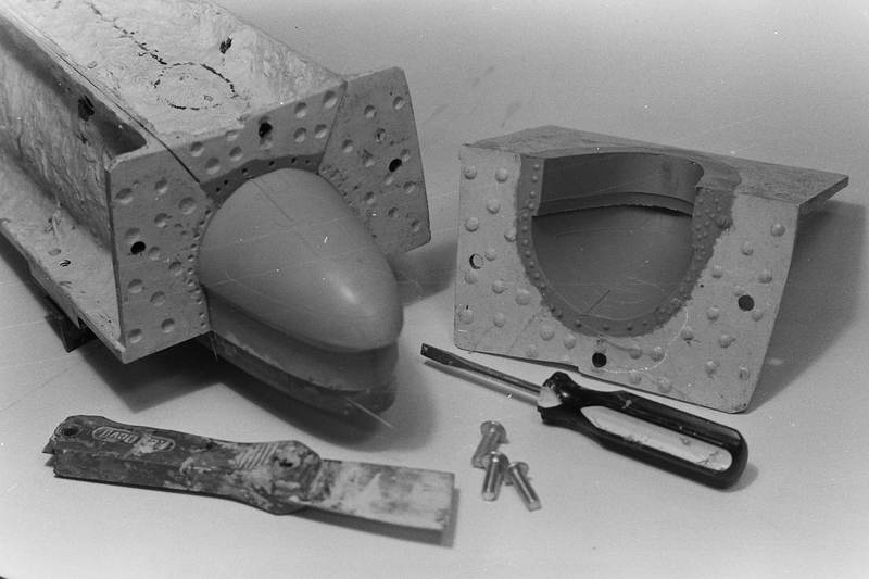
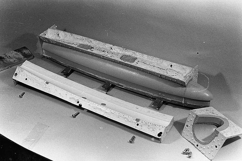
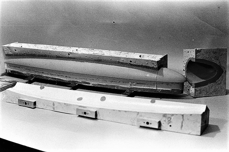
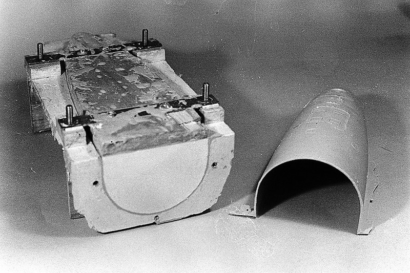
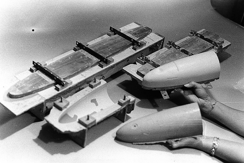
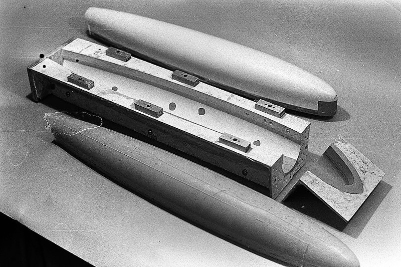
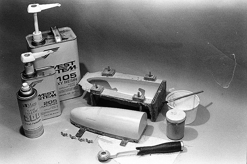
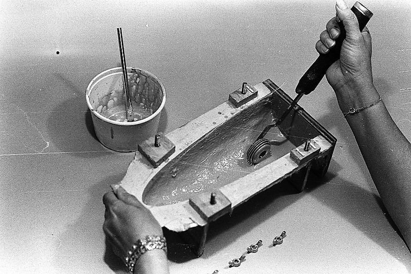
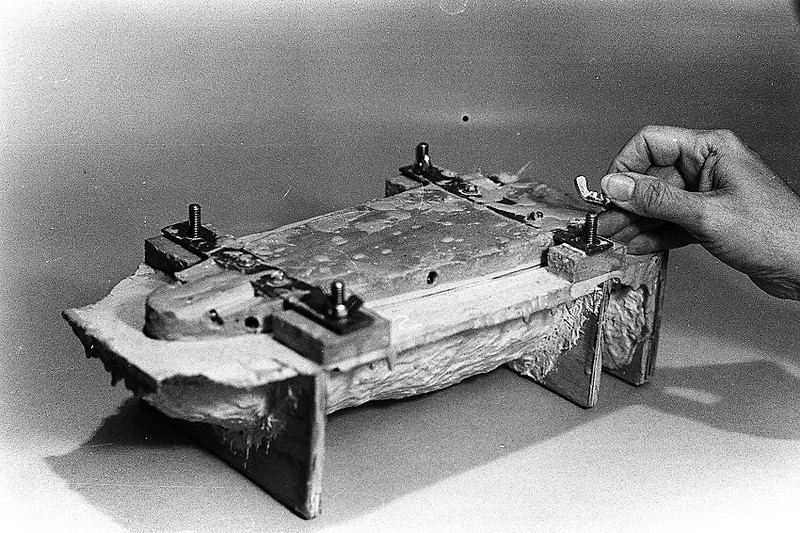
Make the entire bow section a hard-shell mold, but before laying that up clay over the torpedo tube protuberance, like what I've illustrated in the SKIPJACK tooling here.
When you pull the cured mold, you scoop out the clay; drill a big sprue hole over the torpedo tube cavity (where the clay left a void); reinstall the tool over the master; then pour in rubber. You now have a solid hard-shell tool with a rubber element that will tolerate moderate and negative drafts during tool and part separation.
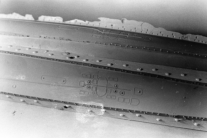
In these two shots you can see the white hard-shell with the darker rubber inserts flush with it. The hard-shell will not flex, but the rubber elements -- over portions of the master with high and even negative draft detailing -- will flex, avoiding entrapment of master and eventual GRP parts formed in this hybrid tool.
David
Leave a comment:
-
Hi Rob,
Thanks for the comments, appreciated, I just need to get David’s thoughts on the last entry as it will affect the formwork for the molds in a big way and I am on the verge of starting fabrication.
Regards,
David HLeave a comment:
-
-
How about cutting out the tubes with an rectangular cut around right in front of the protruding tube and casting them in urethane?Leave a comment:
-
David and Rob,
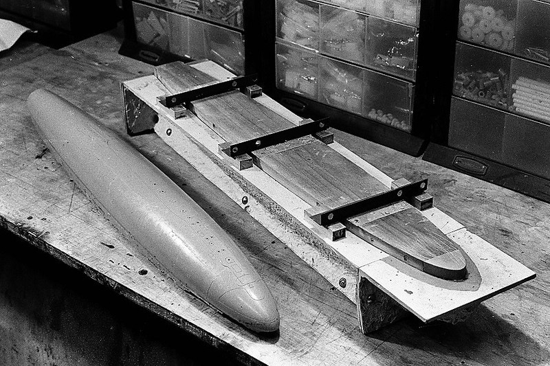
I second what Rob said. I love the old pics. I have seen these before and always wondered how you made the insert. Certainly a complex mold. I have been thinking further over my design and have been looking for ways to possibly reduce the complexity but not reduce the quality of what comes out. I have decided that the small stern section will be a single mold rather that a spit mold. The glass piece just slides out forward. Its going to be quite small too.
I do have a question regarding the molding of the lower bow section where the torpedo tubes are located. Just to familiarize you with the geometry I have included a photo of the area I am going to mold. its in red. The issue is with the Torpedo tubes and undercuts/ Draft angles. I am tossing up whether to make this a one piece mold or stay with the initial two piece mold that originally envisaged. The issue is with the curves and shape of the tube bilges at the back of the tube and the "scoops' at the front, for want of a better word.
Two piece Mold:
Advantages:
Easier to get gel coat and resin over all surface, Easier to get into all corners. Easy to pull finished part. If left for modeler may be easier to put in extra detail and or working tubes before closing both sides.
Disadvantages:
Trickier to initially fabricate and make. If parts molded separately, then joining could possibly reveal slight part line differences? If joined together to mold getting silicon edges to line up perfectly?
One piece mold:
Advantages:
Easier to make. Eradicate an extra part line that runs along the keel. Neater part. More strength built into initial layups? Easier to bolt to main hard shell mold and do one continuous layup.
Disadvantages:
Undercuts caused by torpedo tubes. I know that I can easily pull out the silicon and peal off the part. Hard to get brush in and layup underneath bulges inside caused by torpedo tube doors.
A lot to think about.
Thanks David.
Leave a comment:
-
Leave a comment: