Russian Alfa Class

Collapse
X
 
  • Time
  • Show
Clear All
new posts

  • rwtdiver
    replied
    Today I was granted some time to really try and get some things done on my ALFA!

    Click image for larger version

Name:	ALFA WORK 3.jpg
Views:	362
Size:	85.7 KB
ID:	159650Click image for larger version

Name:	ALFA WORK 2.jpg
Views:	352
Size:	70.6 KB
ID:	159651

    Click image for larger version

Name:	ALFA WORK.jpg
Views:	342
Size:	80.8 KB
ID:	159652

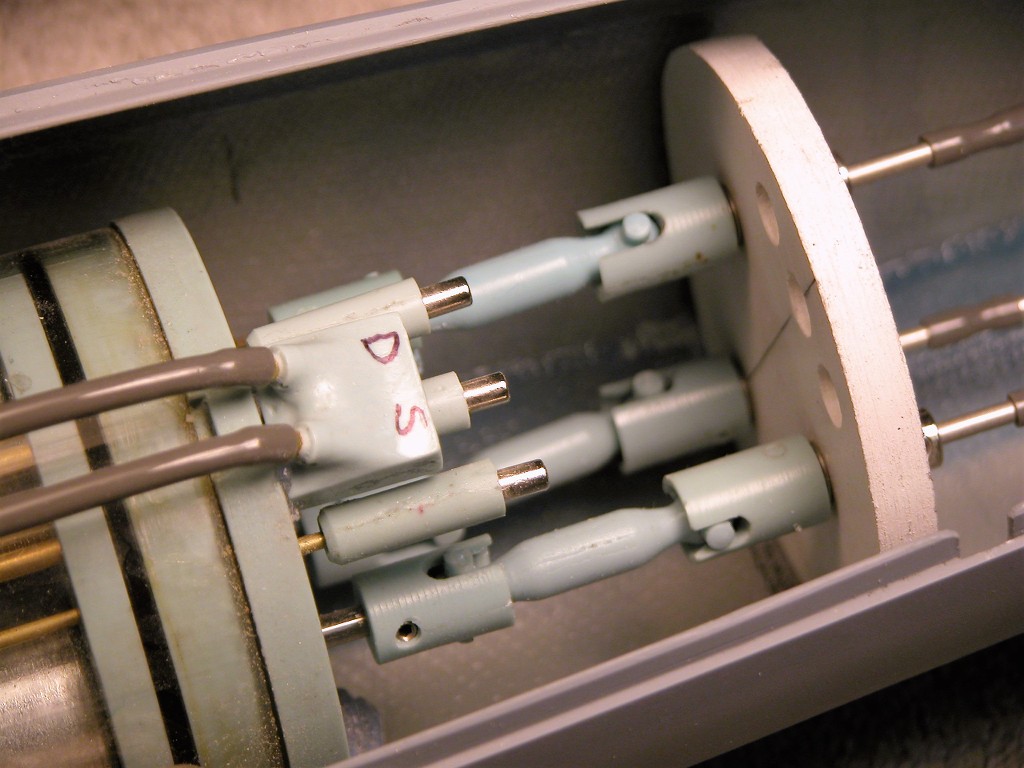
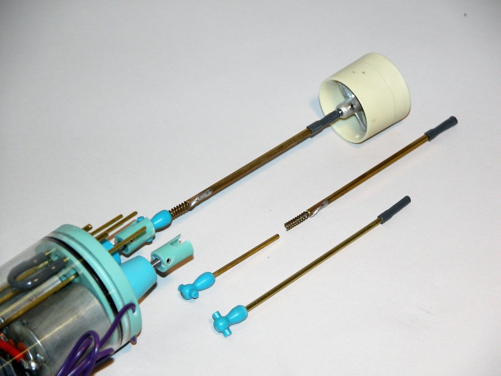
    I had tools, and everything else related to RC sub building out today to try and get this project completed and in the water! I did finish up the 70 mm WTC, and it all works!! I water tested the WTC to check for any leaks and I am happy to say I lucked out on this one. I decided to run my RX antenna on the inside of the cylinder just like on all my SD. My subs do not get much further than 10 feet from my TX and if I do dive it is no more than 2 feet at the most. Never had a problem.

    Tomorrow I will start working on the balance and the trim work!

    Rob
    "Firemen can stand the heat"

    Leave a comment:


  • rwtdiver
    replied
    Originally posted by neitosub
    Looking good Rob! One suggestion I have is to replace those Tamiya-style connectors on the ESCs with Deans plugs. Much easier to plug and unplug, and they take a lot less space as well!

    Cheers,
    Nate
    Not to worry Nate,

    I have not started any of the wiring process yet. The photo just shows were the electronic might be located. I only use deans connectors on all my power supplies! Thank you for your input!

    Rob
    "Firemen can stand the heat"

    Leave a comment:


  • neitosub
    replied
    Looking good Rob! One suggestion I have is to replace those Tamiya-style connectors on the ESCs with Deans plugs. Much easier to plug and unplug, and they take a lot less space as well!

    Cheers,
    Nate

    Leave a comment:


  • rwtdiver
    replied
    CC,

    Your Alfa looks great! The quality of your build speaks for itself! I really appreciate and admire the engineering that you have put into Alfa project!

    Makes me want to take a hammer to mine! :-))

    Rob
    "Firemen can stand the heat"

    Leave a comment:


  • CC Clarke
    replied
    Good progress Rob.

    The first render is my completely re-designed Alpha front end. The Bow Plane Support Platform has two brass bushings and is removable. Note the 2mm high section interconnect frame backstops encircling the inner bow diameter which aid in installation alignment and increased strength at the joint. In addition, each section has internal ribs molded into the hull for increased rigidity and strength. The frames were increased in width from approx 7 to 15mm. Passages for air and water management are included for each hull section.

    The sail needed a facelift to include the access door walkways; limber hole flaps were installed and a lot of extra detail was added, especially on the stern rudder supports. Cooling intakes were added to each side. The only external details I retained from the original model were the five round, vents -just because they looked cool after printing, though I could never find any photo reference to verify them.

    FDM (filament) printing was only used for the interconnect frames; everything else is resin-printed to capture the additional details and minimize the amount of time sanding layer lines associated with that style of printing. Resin printing needs a slight scuffing and it's ready for priming. The only appreciable exterior sanding is at the hull joints. For those, resin can be wicked into the cracks, and cured with a hand-held UV light. The results are very smooth and sanding is minimal.

    Am about to pack all of my printing gear up for our upcoming move to AZ.

    Click image for larger version  Name:	BPSP Composite.jpg Views:	0 Size:	69.2 KB ID:	159392

    Click image for larger version  Name:	Frames Exposed 03.jpg Views:	0 Size:	49.8 KB ID:	159393

    Click image for larger version  Name:	Port Intake.jpg Views:	0 Size:	37.2 KB ID:	159394

    Click image for larger version  Name:	Stern 01.jpg Views:	0 Size:	37.5 KB ID:	159395
    Last edited by CC Clarke; 02-18-2022, 07:56 PM.

    Leave a comment:


  • rwtdiver
    replied
    Originally posted by SubHuman
    My typical driveline setup sees the interface between the drive shaft and motor shaft taking the form of a dogbone connector. That offers some efficient "slop" to take into account slight misalignments. Makes installing the cylinder a snap. I steer clear of intermediate shafts that are basically elongated dogbones. Seems a lot of subs I get in have that setup. Spring for the universal if your shaft is not aligned with the motor shaft. Saves a lot of headache during cylinder installation.

    Bob
    Hi Bob,

    I missed your post here! I agree with you about the final main shaft hook up.

    Click image for larger version

Name:	ALFA DOG BONE JOINT.jpg
Views:	403
Size:	28.2 KB
ID:	159362

    Using the dogbone is what I have used on all my boats. Sometimes to many questions can sure get confusing! I know we have had this discussion before, but sometimes to much blogging and not enough building is not a good thing!

    Rob
    "Firemen can stand the heat"


    Leave a comment:


  • rwtdiver
    replied
    I finished up the supports for the main drive shaft.

    Click image for larger version  Name:	ALFA ADDITIONAL SUPPORT.jpg Views:	0 Size:	84.7 KB ID:	159359

    I am going to finish up the stern section by adding some addition fiber glass to the stern joint and the additional support.


    Rob
    "Firemen can stand the heat"
    Last edited by rwtdiver; 02-21-2022, 01:34 AM.

    Leave a comment:


  • rwtdiver
    replied
    Originally posted by He Who Shall Not Be Named

    One or the other. Not both.

    David
    OK! Thank you!

    Rob
    "Firemen can stand the heat"

    Leave a comment:


  • He Who Shall Not Be Named
    replied
    Originally posted by rwtdiver

    David,

    I totally understand the Dog Bone hook up! But I am getting mixed input as to what my original question was.

    Click image for larger version

Name:	ALFA UNIVERSAL JOINT.jpg
Views:	261
Size:	3.2 KB
ID:	159350Click image for larger version

Name:	ALFA DOG BONE JOINT.jpg
Views:	245
Size:	28.2 KB
ID:	159351

    This to me is a UNIVERSA JOINT! This to me is a DOGBONE JOINT!

    My question was: Do I install both a UNIVERSAL JOINT and a DOGBONE JOINT in combination together? Or just the DOGBONE JOINT as your photos show? As I stated before, I do not see the need for both!?

    I am sorry if I am missing something, but I am getting mixed input!!

    Rob
    "Firemen can stand the heat"
    One or the other. Not both.

    David

    Leave a comment:


  • rwtdiver
    replied
    Originally posted by He Who Shall Not Be Named

    The Dog-Bone universal is a proprietary design. It is but one form of universal joint. There are many others. Typically a complete dog-bone assembly is the dog-bone itself and the coupler(s) it mates to.

    Like this:


    David,

    I totally understand the Dog Bone hook up! But I am getting mixed input as to what my original question was.

    Click image for larger version

Name:	ALFA UNIVERSAL JOINT.jpg
Views:	261
Size:	3.2 KB
ID:	159350Click image for larger version

Name:	ALFA DOG BONE JOINT.jpg
Views:	245
Size:	28.2 KB
ID:	159351

    This to me is a UNIVERSA JOINT! This to me is a DOGBONE JOINT!

    My question was: Do I install both a UNIVERSAL JOINT and a DOGBONE JOINT in combination together? Or just the DOGBONE JOINT as your photos show? As I stated before, I do not see the need for both!?

    I am sorry if I am missing something, but I am getting mixed input!!

    Rob
    "Firemen can stand the heat"

    Leave a comment:


  • He Who Shall Not Be Named
    replied
    Originally posted by rwtdiver

    CC, and David,

    Thank you both for the great input! I now certainly understand what you both are saying.

    So, Bottom line is to add the Universal Joint AND a Dog Bone! Correct?

    Rob
    "firemen can stand the heat"
    The Dog-Bone universal is a proprietary design. It is but one form of universal joint. There are many others. Typically a complete dog-bone assembly is the dog-bone itself and the coupler(s) it mates to.

    Like this:


    Leave a comment:


  • RCSubGuy
    replied
    My typical driveline setup sees the interface between the drive shaft and motor shaft taking the form of a dogbone connector. That offers some efficient "slop" to take into account slight misalignments. Makes installing the cylinder a snap. I steer clear of intermediate shafts that are basically elongated dogbones. Seems a lot of subs I get in have that setup. Spring for the universal if your shaft is not aligned with the motor shaft. Saves a lot of headache during cylinder installation.

    Bob

    Leave a comment:


  • rwtdiver
    replied
    Originally posted by He Who Shall Not Be Named

    Because that 'perfect' alignment you observe as it sits at the room temperature you assembled it at -- without any torque or other loads on the running gear bearings -- will surely get out of alignment when the temperature changes, and the varying degrees of physical distortion the entire structure will undergo because of that; coupled with the twisting and bending the structure will undergo in the dynamic environment of it pulling and pushing, and bending, and twisting its way through an incompressible fluid WILL put that drive shaft out of alignment with the motor shaft.

    Everything to one degree or another is elastic. And the characteristic of that elasticity is a function of its physical properties, temperature and loads presented. We don't have the smarts to predict those distortions, but we have the devices to mitigate the ill effects of those distortions on our machinery.

    That's why the added 'sloppiness' of yet another universal in the drivetrain.

    David
    CC, and David,

    Thank you both for the great input! I now certainly understand what you both are saying.

    So, Bottom line is to add the Universal Joint AND a Dog Bone! Correct?

    Rob
    "firemen can stand the heat"

    Leave a comment:


  • CC Clarke
    replied
    Ditto to that. As an engineer, before we "qualify" a new product before release, it is stress-tested beyond the predicted max loads expected, while operating at high and low temperature extremes and humidity levels. Once X number of units pass qual, the design is officially locked for production, No changes are allowed afterwards without re-qualifying the revision, and that is exceeding rare due to the time and expense involved.

    At this level, a little slop is an ounce of prevention.

    Leave a comment:


  • He Who Shall Not Be Named
    replied
    Originally posted by rwtdiver
    The shaft from the motor to the shaft from the prop, is dead center! using a universal joint to hook them up would be perfect. So why use a dog bone along with a universal joint? The only reason I see is ease of installation only! Why add addition sloppy connections to an already perfect in-line installation with the just universal joint?

    Rob
    "Firemen can stand the heat"
    Because that 'perfect' alignment you observe as it sits at the room temperature you assembled it at -- without any torque or other loads on the running gear bearings -- will surely get out of alignment when the temperature changes, and the varying degrees of physical distortion the entire structure will undergo because of that; coupled with the twisting and bending the structure will undergo in the dynamic environment of it pulling and pushing, and bending, and twisting its way through an incompressible fluid WILL put that drive shaft out of alignment with the motor shaft.

    Everything to one degree or another is elastic. And the characteristic of that elasticity is a function of its physical properties, temperature and loads presented. We don't have the smarts to predict those distortions, but we have the devices to mitigate the ill effects of those distortions on our machinery.

    That's why the added 'sloppiness' of yet another universal in the drivetrain.

    David

    Leave a comment:

Working...