

Is that a scale model of the Hunley? I thought the baot was longer and more slim....
-
-
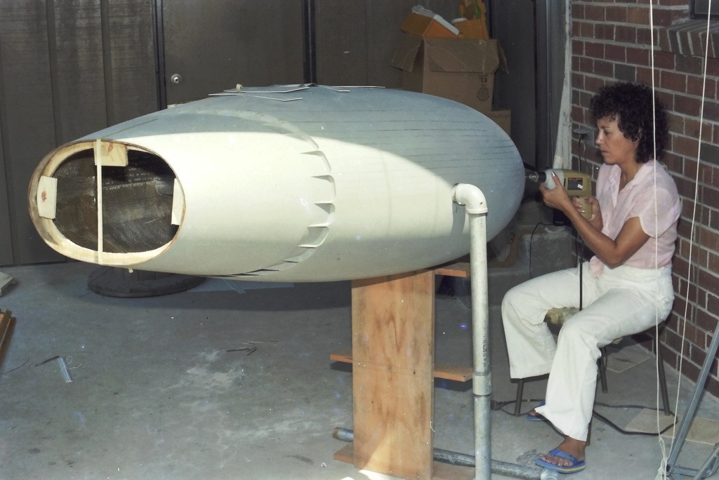
This particular model of the HUNLEY was built by another party, obviously using documents prepared before recovery of the prototype. Flawed in all respects. My job was to make it a practical r/c submarine, not correct its many dimensional and detail flaws. The only significant thing I did to get this boat looking better was to make the rudder mechanism 'real'; its function emulating that of the HUNLEY.


DavidWho is John Galt?Comment
-


Who is John Galt?Comment
-


Who is John Galt?Comment
-
Really nice machine work there. Wish I had the same tools.Comment
-
Nice! I love tis kind of work.Comment
-
DEADLIGHTS
part-3
Transparent Plastic Inserts and Fiberoptics I've covered the two means I favor to produce thin walled transparent structures. Heat forming plastic sheet, and liquid-to-solid. But, in the majority of our work transparencies are rendered as either thick hunks of acrylic, cut from sheet or purchased as rod or square sectioned extrusions. The disadvantage of this type transparency is the inability to use it as a non-distorting lens to any detail built into the models interior; unsuitable for viewing the models interior, but excellent as a light focusing conduit when back-lit from within. Inserts are fine for projecting light to the outside world.
Typically a significant portion of the insert transparency resides well past the inside walls of the models structure. This to gather the rays of an internal light source(s), and project those light rays to the outside observe. A well lit model interior, as viewed through a deadlight; cockpit; port-hole; navigation light lens; search-light lens; astrodome, or any other type transparency – radiates light from the models interior through the transparencies.
This discussion deals with clear or colored semi-clear inserts. Their installation and use.
On this 1/187 Andreas Schmehl USS NAUTILUS kit, I initially intended to back-light the two lower sets of deadlights – as built the NAUTILUS had no less than three levels of deadlights at the leading edge of its huge sail!
Those two levels of deadlights started life as long inserts of .375-inches thick acrylic – you see those two blanks at the foot of the sail. I figured they would do a better job of catching an internal light-source than the epoxy liquid-to-solid deadlights at the upper row in front of the open bridge. Up there there's no room for any but a conformal liquid-to-solid transparency. Back to the inserts:
In order to evenly catch the light all internal faces of an insert were machined flat and sanded with Toot! Toot! Outta my Way! grit – the even, but rough surfaces, diffusing light evenly, presenting a uniform glow when back-lit, and not a random collection of disturbing hot-spots.

The two deadlight inserts, after being CA'ed in place, were filed and sanded down to follow the contour of the sails leading edge. To ease the later polishing task the outside surfaces of the faired in inserts were given several coats of CA to fill sanding marks or any open seams between insert and GRP sail. CA is clear, sets quickly, and takes to sanding and polishing just like acrylic.
The CA over-coat was then worked with descending grits of sandpaper, stopping at grit. At that point I continued with descending grades of liquid polish until the acrylic inserts were optically clear.

The deadlights are masked off and the first coat of primer goes down – this to better identify tool marks and open seams that were not adequately filled by CA or air-dry touch-up putty earlier. With the masking still in place problem areas were filled and sanded and spot primed. Once all surfaces outside of the masking were smooth and blemish free, the masking is removed and saved; as it needs to be used again later, as the model is painted and weathered.
That long strip of masking tape under the middle set of deadlights is there to insure that all deadlight masks are of the same height and spacing. It's removed before painting and priming.

If the transparencies are to be back-lit it must be assured that light only is seen through the transparencies not portions of the model that are supposed to be opaque. Prevention and identification of light-leaks is the next operation.
The deadlight masking still in place, black paint is sprayed over the masked areas and over those portions of the hull where the light source is housed. The sure-fire way of finding light-leaks is to darken the work space, wait a few minutes so your eyes get 'night vision', then turn on the models internal light source and look for light leakage; light where light should not be. Repeated coats of black are laid down over the offending areas, and the test repeated till only the deadlights glow in the dark and nothing else.
It's a wise practice to retain the masks, as they will be needed later as the color coats and weathering are applied.

Acrylic round stock was used to form the deadlights within this commanders copula/access hatch mounted atop a 1/12 scale USS ALLIGATOR filming miniature we built for a TV producer who was working up an episode for the Discovery Science Channel.
The copula/hatch clear deadlights were represented by simply turning an over-size rod of acrylic to a diameter that made each transparency an interference fit to a port-hole; each end of a transparency polished to optical clarity; all made fast with a heavy coating of CA adhesive applied within the cupola/hatch.

The ALLIGATOR effects miniature (unlike most effects miniatures) was an unrestrained r/c vehicle; free to maneuver in yaw and depth under radio control.
We were on set for a three-day shoot; most of it done at the David Taylor Model Ship Basin's enclosed maneuvering and sea keeping (MASK) tank and open-air explosive basin.
Here I've unceremoniously tossed the miniature into the MASK pool. (this is one of the facilities where Government Scientists and Engineers tests huge r/c models of surface and subsurface design articles).

The miniature being placed on the mark for another 'take'. Depth to the bottom on this side of the outside explosive basin was about 25-feet. Even at this relatively shallow depth most of the red from the spectrum has been blocked out by the water. If any dry space within the miniature was going to leak... this was the place for it!

The ALLIGATOR's cupola/hatch and seating flange formed a watertight union and was subjected to about ten-PSI of water pressure during filming at the explosive basin. I was pleased to find no water had leaked into the cupola/hatch or WTC in the evening, as I performed post-mission maintenance and repair work.

Not only were the deadlight transparencies made watertight, so too were the practical cupola/hatch structure itself, as you can see here: The units hinge and locking dogs were practical. And a proper O-ring seal, set within the seating surface of the cupola/hatch -- insured a water tight seal when it was dogged down upon the flange.

It's good practice to have something interesting to look at on the inside of a structure featuring an optically clear transparency. In pursuit of that objective I sculpted a scale head and shoulder portion of Ab Lincoln. The Commander In Chief was positioned within the cupola.
(When I'm amused, I'm easier to work with).
The Director wanted the ALLIGATOR miniature to stand in as a proper display model in a scene where a historian addressed the audience as he viciously jabbed the model with a pointer, to accentuate his narrative about the Yankee submarines special features. (I think he was a Rebel at heart)
Hence the need of a scale Diver walking on the bottom, having just dropped out of the ALLIGATOR's lock-out chamber – further illustrating the unique capabilities of this Civil War era submarine.
Professional model-building is often more than model building!

Short lengths of acrylic rod were used to represent the four deadlights around the cupola/hatch as well the many deadlights that ran the length of the ALLIGATOR hull, port and starboard. Their function would have been to help illuminate the interior for the poor slobs hand-cranking the propeller or working the Diver's air-pump.
That period Diver fellow, taking a leisurely slogging through the river muck; on his way to perform some mischief against Rebel assets.

The guy holding the miniature – member of a team that usually is employed to work in the ocean, recording stuff for yet another, 'Shark Week' episode – is there to get the miniature positioned over its mark for a take, or bail me out if I loose control of the thing. Out of frame here, another Diver films the action.
(All joking aside – these guys were true professionals in and out of the water; things worked well on that shoot because of them. They knew their ****!)
Meanwhile.
I'm topside, standing dangerously close to the end of the pier, transmitter in hand, looking down, trying to get a bead on the miniature, and driving the damned thing as directed – deeper than I had ever driven an r/c submarine. All that going on as the Director screams stuff like, “Left turn!... I said LEFT TURN!... No!.. You're other left”. There were moments when I almost tossed him the transmitter.
No matter. We got the shots in.

Kit Enhancement with Transparencies The trailing edge of this Moebius 1/128 SEAVIEW kits sail was enhanced by adding two transparencies. The upper cavity to receive an emergency running light lens; the lower, longer opening was for a protective lens covering a stern-view CCTV camera.
I made use of the clear polystyrene parts tree that came with the kit – a 'runner', an element of an injection formed kit that gets the molten plastic into the tool cavities during manufacture. When you buy a kit that has clear parts, make it a habit to keep the clear runners for future use.
The stern light 'bullets' were turned from acrylic rod.

I roughed out the emergency stern light and camera lenses to the required shape before gluing them into their respective cut-outs in the sail. They were installed and made fast with CA adhesive.
Wherever possible make use of excess material as a handle as you shape, install and glue the transparency in place. The excess material is either snipped or sawed away and the rough-cut piece filed, sanded and polished to contour.

Movies don't get made until some wild-eyed Producer sells the story and outlines the mechanics of the production to the prospective studio and money-men. Sometimes, as part of the sales package, a models of vehicles and/or sets are elements of the Producers pitch. We've built a few of those.
This particular model, a concept of the still-at-the-time-confidential B-2 bomber, the subject of a proposed spy-thriller. So, this third-string, nobody, “Producer” contacts me, we come to an agreement, I build the model and send it to him. He disappears.
We never got paid for the work. Ellie was not amused!

Construction was easy as the entire form of this B-2 was flat planes of polystyrene sheet with only the tips of the wing and nose radome describing a curve, everything else was hard-edge. I was working off an illustrated magazine article, so I assume the artist was thinking of the faceted, very ugly F-117 when he dreamed up this fictitious B-2 bomber.
As the model was too small to represent a cockpit I simply painted the bottom of the inserted acrylic piece gray and left it at that. The acrylic transparency was dropped into a cut-out atop the wing, glued, and faired in smooth with the surrounding surfaces. Masked off, I proceeded with the funky 'desert camouflage' scheme the Producer wanted.

Back-lighting transparencies It's one thing to let ambient outside light sources kick around within and behind a transparency, the effect is usually pleasing and reads to the casual viewer as 'real'.
But, its a different game when the transparency is back-lit; where the light source is from within the model – the objective, most of the time, is to achieve an even glow over the entirety of the transparency.
Back-lit transparencies are either microscopically scratched/pitted or given a very flattened clear-coat on their inboard faces to present diffused light, not an interior.
This 58-inch DeBoer Hulls SEAVIEW model features back-lit transparencies as described above, but also features the big bow, optically clear, windows of the observation compartment with all its interior detailing – in that situation internal lights, themselves hidden from view, illuminate and present internal details of the model.

The actual effects miniatures from the movie and TV show had practical running lights on the sail, but they were white. The sailor in me just had to make them a proper green on the starboard side, and red on the port side.
The 58-inch long SEAVIEW was a perfect candidate for use of unaltered LED's of the appropriate colors sticking out the sides of the sail.

At the bow there was the forward search-light; the port bottom-illuminating lamp; and its counterpart on the starboard side. All three were back-lit from 12-volt car turn-signal incandescent bulbs – chosen for their exceptional brilliance.

Demonstrating the brilliance of the search-light and bottom-illuminating lamps. All three lenses were turned from acrylic rod.
I'm holding the sail running lights. Note the current dropping resistors, needed to limit current flow into the LED's to less than 2mA.

Small grain-of-rice sized incandescent bulbs represented the SEAVIEW's stern lights.


UQC intercept:
“Admiral Nelson to pursuing UN submarine: Disengage! Or soon discover your actual Design Depth... continue to follow at this descent rate and you'll find out, fool!”

Who is John Galt?
Who is John Galt?Comment
-
David,
Thank you for the entire series on how to do the deadlights! You truly are a Master at your craft! Merry Christmas!Comment
-
DEADLIGHTS
part-4
A welcome departure from the ill-fated ENTERPRISE job was installation of a single white identification lamp just forward of the access hatch atop the sail of this 1/12 scale KAIRYU, WW-2 era Japanese coastal defense, two-man submarine. The single lamp used only during training, identification, or retrieval.
The operational profile of these little submarines was a simple one: they would operate for only one sortie. Because of a shortage of the planned torpedoes, these submarines would, instead, engage Allied amphibious forces as explosives laden suicide craft.
Thank goodness for the atomic bombs!
(My dad was training for his role in the invasion of the Japanese home islands When several pounds of fissionable metal halted the war).

For the model a miniature grain-of-rice sized incandescent bulb was housed within a turned acrylic rod that represented the actual boats waterproof lens, which was protected by a metallic 'cage'.

Surprisingly, this model became my go-to vehicle for towed camera jobs owing to its long horizontal stabilizers and small screw. The tow-line seldom got entangled in the screw, and the boats ability to turn and hold commanded depth is exceptional. You can see it in action during the later portions of this video: https://youtu.be/H4q1NO_IQGk (starts at 52:00)

This 1/96 Thor SEAWOLF model featured sail mounted port and starboard running lights. The two colored transparencies (green for starboard, red for port) were back-lit by a single common incandescent bulb within the sail.

As is my practice on any model that will be lit from within I paint all the opaque areas black, darken the shop and after my 'night-vision' has kicked in the back-light(s) is energized, and the surface of the model checked for any light-leaks. Once any problems are found and fixed, the model is given the first color coat (for modern submarines, the topside areas are a very, very dark gray).
As color tinted sheets and extrusions of acrylic are hard to find I often resort to using the handle portion of an appropriately colored tooth-brush, cut to shape and inserted into the model to form the semi-transparent colored lens.

An anchor-light atop the SEAWOLF's upper rudder was a grain-of-rice incandescent bulb. Its wires running down the hollow rudder operating shaft.

This Thor 1/72 ALFA model also employed semi-transparent tooth-brush colored lenses to represent the port and starboard running light lenses. Using the unused portions of the tooth-brush as a handle, it's an easy matter to cut the end to the desired rectangular shape. Snipping the rectangular pieces off when brought to proper shape.

Incandescent grain-of-rice bulbs were used to represent the stern and anchor lights, both affixed to the ALFA's upper vertical stabilizer.

A single incandescent bulb, the mast head-light, was fit atop the ALFA's sail.

Ellie holding the completed ALFA model.

The 1/72 ALFA making this pool safe for Communism.

The only movie Ellie and I secured screen-credit on was a horrible little slasher SF thing called, Midnight Movie Massacres (AKA Attack From Mars).
Though we had done work for such productions as The Hunt For Red October, Crimson Tide and several ST properties our anti-union position and status kept any acknowledgment of our work off the big-screen.
We not only designed and built the effects miniature, we spent two weeks at the Missouri studio to rig and 'fly' the miniatures as well as building two forced-perspective miniature sets. Hell!... Ellie even fabricated a 15-foot long nose booger (don't ask).

We were involved from the beginning of the production, working off the initial screen-play I story-boarded all scenes featuring a miniature. From those illustration the size and capabilities of those miniatures was established. All of the work being done in the garage and back-porch of our Navy housing apartment!
The smallest miniature was a weird looking 'bad-guy' spaceship with round port holes that had to be back-lit to glow brightly. The body and fins were made from polystyrene foam and then overlaid with epoxy saturated fiberglass cloth.
Here's that miniature just before installing the acrylic rods that would form the port-hole transparencies.

This miniature started life as a lathe turned hunk of polystyrene foam – that specific type expanded plastic selected, as the requirement was to skin it with resin saturated glass cloth then dissolve the foam core away to render a hollow GRP model.

The 'fins' and other appendages were made up to the hull after it had been skinned with GRP. Here are foam blanks of those fins fresh from the band-saw. A foam-rasp and TIPS'N TRICKS sandpaper got them to shape quickly, after which they were epoxied to the hull at random locations, and GRP skinned – the objective was to give an asymmetric, unearthly, appearance to the miniature. The polystyrene foam hull blank is to the right, ready for turning.

After laying down several laminates of epoxy saturated 10-ounce fiberglass cloth to the hull, gasoline was poured into the nozzle end of the hull, quickly reducing the rigid polystyrene foam to a goo that was poured out leaving a hollow GRP hull.
This 'lost foam' technique achieves a hollow GRP hull without going through the classic pattern-tool-part process; a quick means of fabricating a one-off item.

As all transparencies would be circular port-holes I selected a variety of acrylic rod diameters and inserted them into random holes in the miniatures hull, securing them with CA adhesive. Here I'm grinding excess acrylic down to the surface of the hull.

Before painting the bad guy spaceship I lit it up to find the light-leaks. Masking was reapplied in those areas that leaked, and more primer was sprayed over the offending portions of hull.

The completed 'bad guy' spaceship undergoing a last lighting test while mounted on the shop pipe stand. Note that the pipe supporting the model acts as the conduit for the wires that energize the single bulb suspended in the middle of the hollow hull.

The biggest effects miniature we made for this flick was a tear-drop shaped mobile space-station model. A hollow GRP structure it was festooned with hundreds of port-holes, all back-lit from an internal source. The forward portion of that miniature mounted on its pipe-stand as Ellie drills out holes for lengths of acrylic rod.
Some of the round acrylic rod projecting into the hull can just be made out in this shot. The after, removable 'stinger' section of the miniatures, which permitted access to the two florescent light sources within, is out of frame. The temperature of that light, captured by the acrylic inserts, would evidence as a bright green glow seen through the round, polished 'port-holes' laying flush with the outer surface of the model.
This part of the work was laborious! A row of holes would be drilled; then take a break from that by snapping rod and inserting the pieces into the holes; slather on some thin formula CA, and saw each one off just a fraction of an inch proud of the models surface; then get back to punching more holes.
Once all the inserts were in pace a belt sander ground the rod down to a point where only a very small amount of transparent rod projected above the surface of the hull. The rods were brought flush to the hull with a sanding block.

As this miniature represented a mobile space-station over a thousand-feet in length it was outfitted with numerous small bumps and nondescript shapes to suggest the massive size of the 'real thing'. With the stern 'stinger' attached, this miniature was effects miniature was about seven-feet long!
I'm loath to just tack down random kit parts (which had been rage in the industry since 2001 A Space Odyssey). We don't do that! Each and every part added to this big miniatures was vacuformed from dedicated patterns.

Preparing the big space-station miniature for its first light-leak test. The stinger is secured temporarily prior to the test. It would be glassed in place and the seam totally erased later as we got to the painting stage. Just above the pipe-stand elbow you can make out the extension cord that leads from the internal florescent bulbs to the outside world.


The completed space-station miniature at the Missouri studio (an old Masonic Temple) in our assigned work-space, the ball-room kitchen. For two weeks Ellie and I tended to and operated the miniatures. We were pulling eighteen-hour days, but it all was the adventure of a life-time.

One story element of Midnight Movie Massacre dealt with a time machine. In the shape of a classic flying saucer. My story board cells called for this thing to 'fly' using a wire suspension rig. Here you see the completed miniature, about five-feet in diameter, hung from the garage girders, being tested before being crated up and sent to Missouri.
Power for the back-lit lights near the center bottom of the craft came down through two of the four suspension wires. The transparencies, like those of the space-station, were short rods of acrylic back-lit from within. In this case three very bright incandescent bulbs.
Does this saucer look familiar? Check out the saucer shown in the opening credits of, The X-Files.
(By the way, that's the 17-foot SEAVIEW miniature in the background... we were busy little beavers in the mid 80's).

The labor intensive chore of installing hundreds of dedicated transparencies into an opaque hull was eliminated by the Industrial Light and Magic (ILM) crew as they worked up the miniatures for the (then) new Star Trek series, Star Trek The Next Generation – Those guys, the cream-of-the-cream in the model-building game, simply made the entire miniatures hull transparent; or at the very least, semi-transparent. With a semi-transparent all all that is needed after the lay-up and polishing is simply to apply laser self-adhesive masks, paint the thing, pull the masks, and job done. I simplify, but that's the gist of it. Pretty damn slick!
The models outer structure is GRP, the laminating resin is clear and the glass weave of the laminates becomes semi-transparent when saturated with the binding resin. Below is the result. This shot of the big ENTERPRISE-D 'hero' model.

ILM got the ball rolling on that series. Later miniature work was farmed out to Greg Jein's outfit. Ellie and I already had a professional relationship with this guy, the best free-lance model builder in the game. Through the course of the show Greg contracted with us to build masters of just about every 'warp engine' sub-assembly seen on the little-screen.
For example, this finished Klingon ship, nearing completion at Greg's shop featured warp-engines that started life in our Virginia Beach garage as masters from which his guys made tools and transparent parts that would be back-lit, like you see here.

After a script was approved by the studio, Greg was usually given only weeks to build the required miniatures, that kind of squeeze necessitated the engagement of third-party contractors like us. Just more balls added to the ones he was already juggling.
For this particular job he tasked us to also produce the rubber tool his guys would use to make the translucent warp engine bodies. Here's the completed Klingon warp-engine mounted on mold boards with their associated containment dams ready for the first pour of room temperature vulcanizing tooling rubber.

We eventually got so many of these quick-and-dirty pick-up jobs for STTNG that Greg threatened to send us matching crew T-shirts and ball-caps emblazoned with the Paramount logo and big letters spelling: WARP-ENGINES R' US. (Still waiting!)


Transparencies within transparencies.
This display model was commissioned by a defense contractor that was selling fiberoptic data buses and multi-task, sit-down and stand-up information display and control consoles. The client provided the documentation and directed us to build a model display that represented some of their product as it would be applied to the Royal Australian Navy's (RAN) COLLINS class submarines. The result was this rather large cut-away of a COLLINS control-room.
I later learned that heads rolled when the display was presented at a defense convention. Apparently a RAN liaison or Australian government official was browsing the booths when he came across the model. He observed that the display contained 'confidential' elements.
Something went down; we never heard from that client again.
Where was I? Oh, yeah... back-lit transparencies.


Seven multi-task sit-down station cathode ray tubes (CRT), and the stand-up dead reckoning trace (DRT) navigation console CRT were back-lit to project ship and environment displays to the operators and conning team. That was the emphasis for this display – to show off our clients hardware in model form.
Here I'm showing how these cast resin sit-down multi-task console models went together, and how LED's back-lit technical display transparencies.
To prevent 'hot-spots' on the CRT displays I placed cotton and a sheet of translucent plastic sheet between the LED's and transparency – these interface items worked to evenly distribute the back-lighting across the entire face of a transparency.

Each display transparency was a frame of exposed and developed 35mm black-and-white film. Film I shot with my camera of documents provided by the client (those documents possibly the source of the above brou-ha-ha).
All but the chart back-lighting was hooked up to a 555 timer chip to produce a 'flicker' effect – an artifact of the old CRT technology. A barely perceptible dynamic that helped breath life into an otherwise static display.
Hey!... you do what you can to make things interesting; things that catch the eye of the government appropriations people as they migrate from booth to booth (after tanking up at one of the many convention 'hospitality suites'). The Stories Ellie and I could have told!

This big stand-up console is the Navigator's dead reckoning trace (DRT).
(A system that provides the Quartermaster's the ability to estimate the boats position by integrating course, speed and time – own ships position displayed as an illuminated moving dote under a chart representing the area of operation).
The big opening will receive an array of incandescent bulbs that will back-light a chart.
The smaller opening, back-lit by green LED's, represents another multi-task CRT display.

The DRT in action. Can't make out the chart overlay because of the long exposure needed to make the shot. However, the detailed navigational chart being back-lit by the array of incandescent grain-of-rice bulbs (and thank goodness the client never checked) is a topographical map of our Virginia Beach r/c boat clubs favorite play-ground, Lake Trashmore.
To keep from going insane, pro's will take every opportunity to sneak in little (and sometimes not so little) Insider gags the client won't catch but would be appreciated by other pro's in the know. It's a game we played. There are famous/infamous examples of this:
Greg Jein's crew festooned the Close Encounters of the Third Kind, Mother-Ship with little mail-boxes, an R2-D2, and crew names spelled out in port-hole lights; the smaller, The Abyss OHIO class submarine miniature had a screen door on the non-filming side of its sail; the Disney NAUTILUS hero model had 'goff' spelled out in rivets on one side; I stuck Ab Lincoln in the cupola of the ALLIGATOR effects miniature; and panel lines of the hero ENTERPRISE-D miniature spelled out, 'FU'. Long hours in the shop exacts a price.
And I went a little nuts on this job too.
The COLLINS control-room back-lit displays had more than one gag; a wrench teetering at the edge of a cabinet directly over the Navigator's head ready to clonk him the moment the boat took a down-angle; a drip-pan with loose tools in it way behind the radio-crypto-room enclosure; and a rather racy Playboy pin-up hung on a cabinet next to the ship-control station (Ellie was not amused – it came down within seconds of its going up).
Fun and games in the wee morning hours with a deadline just around the corner.

Who is John Galt?
Who is John Galt?Comment
-
David,
Those are some great photos of your past accomplishment's! I do not have the right words to even begin to say what should be said! I guess I should just leave it at that and just say I am extremely impressed with what you have accomplished in the modeling world!
I have to say this as well, you and Ellie certainly did make a grand wonderful team! God bless you both!!
Rob
"Firemen can stand the heat."Comment
-
-
Spring assisted?Make it simple, make strong, make it work!Comment


Comment