Japanese Class A 1/16

Collapse
X
 
  • Time
  • Show
Clear All
new posts
  • MFR1964
    Detail Nut of the First Order
    • Sep 2010
    • 1290

    #31
    Von,
    Did you run it also underwater?, or did it run hot on dry land?, i've tested mine both ways, no problem at all, you have to keep your gears as sloppy as possible, i run metal gears.


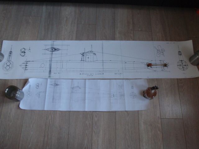
    The second step is made, got me my enlarged drawings, i must say the length is not bad about 137,5 mtr or 4 foot 7", also want to thank both David and Gene to make this possible, next step is making the ribs and getting some RenShape.


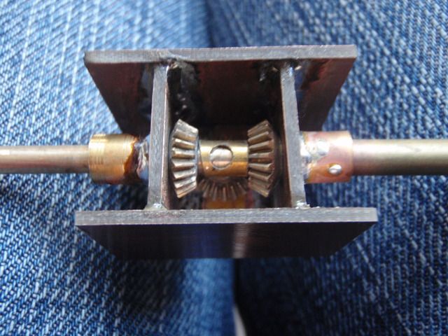
    This one is for you George, as you can see i use three pinion gears, you could go the way like Von, looks to me much easier to make without a lathe, as for the brand of the pinion gears, i suspect they are from Aeronaut, i bought these from the shelf at the local hobbystore, so i really don't now the exact brand.


    Manfred.
    I went underground

    Comment

    • Von Hilde
      Rear Admiral
      • Oct 2011
      • 1245

      #32
      Manfred, I ran them dry first then wet. They were cool wet. I am building another but some internal modifications. No more sloppy gears. I want to try those pinion gears , but use two latteral trunions. Dave talked me into two idlers to bear the torque. I will try that set up in a round container so it will fit aft of where the cone seperates from the hull, With a shorter set of shafts, there wont be as much vibration, and of course a set of semi ballanced props will help. I found some sutable Raboesch 1940 design 4 blade. The nice thing about them, is you can get a large diameter LH for the forward and a smaller diameter RH for the aft. Flat hubs, so you only need to cone the aft with a small model plane spinnerClick image for larger version

Name:	Raboesch type A.jpg
Views:	1
Size:	4.9 KB
ID:	9776820 degree pitch at the hub. Found a nice supply of cone gears, plastic with brass hubs, and in colors. Robotics supplier in England, called Technobots, reasonable as wellClick image for larger version

Name:	cone gear.jpg
Views:	1
Size:	2.6 KB
ID:	97769
      Last edited by Von Hilde; 03-17-2015, 03:27 PM.

      Comment

      • He Who Shall Not Be Named
        Moderator
        • Aug 2008
        • 12253

        #33
        Of course, if you are lazy, you can make either of the two propellers free-wheeling and let it pin-wheel in the water.

        M
        Who is John Galt?

        Comment

        • He Who Shall Not Be Named
          Moderator
          • Aug 2008
          • 12253

          #34
          Originally posted by HardRock
          The central (black) mounting ring has three lugs that carry three spacing rods to mount on the silver bracket at the left of the photograph. Just read this back and even I don't understand it. Here's a photograph.[ATTACH=CONFIG]30428[/ATTACH] or two [ATTACH=CONFIG]30429[/ATTACH] [ATTACH=CONFIG]30430[/ATTACH] The front out runner is directly connected to the large (black) forward spindle and the rear out runner drives the central (silver) spindle. It needs two ESCs to run and provides quite a serious amount of contra-rotating power.
          Slick! Good catch. Web-site?

          M
          Who is John Galt?

          Comment

          • MFR1964
            Detail Nut of the First Order
            • Sep 2010
            • 1290

            #35
            Try this one David, sorry, posted about the gears Von found, need my glasses badly.


            Not yet have found the supplier of my brass gears, so the search will go on.

            Von, good to know such things you experience with your contra rotating box, props are still way ahead for me, first get me a tower, and building a master for the hull.

            Manfred.
            Last edited by MFR1964; 03-17-2015, 04:45 PM. Reason: too fast link-action
            I went underground

            Comment

            • Von Hilde
              Rear Admiral
              • Oct 2011
              • 1245

              #36
              If I was lazy, I could just glue em together. Or better yet glue em solid and just look at it. Yesterday in KW history, in 1973. The Howard W Gillmore left and went to Sardinia. A bit of submarine trivia.

              Comment

              • He Who Shall Not Be Named
                Moderator
                • Aug 2008
                • 12253

                #37
                Originally posted by Von Hilde
                If I was lazy, I could just glue em together. Or better yet glue em solid and just look at it. Yesterday in KW history, in 1973. The Howard W Gillmore left and went to Sardinia. A bit of submarine trivia.
                Small world, it was the GILMORE that brought me to Key West and the Submarine Service -- A few months after we transferred out of Charleston to KW I cross-decked to the TRUTTA. Nine months later I had my Dolphin's!

                ... thanks for leaving the door open for me, Dave.

                M
                Who is John Galt?

                Comment

                • HardRock
                  Vice Admiral
                  • Mar 2013
                  • 1609

                  #38
                  Originally posted by He Who Shall Not Be Named
                  Slick! Good catch. Web-site?

                  M
                  HobbyKing warehouse in Hong Kong.

                  Comment

                  • HardRock
                    Vice Admiral
                    • Mar 2013
                    • 1609

                    #39
                    Just looking for it now. It was about A$65.00 landed here when I purchased it a year ago. I can't see it there at the moment. If you can't find one, let me know and I'll swap mine for a few 65/76 torpedoes.

                    Comment

                    • Von Hilde
                      Rear Admiral
                      • Oct 2011
                      • 1245

                      #40
                      Manfred,, When you make the plug for the mold with the Ren Shape, there wont be much to turn on the lathe, just a simple spindal, correct? Are you going to construct it in sections? I was thinking, I will seperate the hull sections,into 3 main hull parts and the bow section seperate as well as the rudder and plane sectons. In Genes drawing on the 1 foot scale line. Respectively , I will call them sections. So, Bow section, goes to the 11 foot mark, stern starts at the 66 where the seperation bolts are. The main hull from 11-66, front slightly taperd from 11-25.5 center section can no taper 25,5-42 and the after longer taper 42-66. So basiclly two cones and can in the middle. For me that wont take long to build with aluminium and JB weld and epoxy. Less time than for that box, that kept me awake for a couple nights. The bow section will require some thought however. Lots of cool detail, and compound and complex bending of plates. Almost as crazy as the type IIa. I'll watch you to see how you build the tower. Thats going to be the fun part. Aft section is basic Blimp, but lots of nuts and bolts wires and weld seams. more fun. Like you said in the beginning of this thread, I must be crazy as well, to put another plate on the table" but this thing has got me by the Cojone's.

                      Comment

                      • MFR1964
                        Detail Nut of the First Order
                        • Sep 2010
                        • 1290

                        #41
                        Von,

                        I share your idea, it also had crossed my mind, more to cut down the lenght for transportation, i'm thinking about deviding the boat into three section just like you've described, using a kind of bajonetlock combined with strong magnets, this way you have both access to my two shooter and the rear part, in the middle part a SD, all connections made by magnets except the driveshaft.
                        Just spewing out idea's, not sure if they will be practical, we'll see in the future.
                        Started with cutting up one of the drawings for making the basic layout of the tower, i ordered two actually, one for cutting up and making molds, the other for reference, as a base i will use copper cladded GRP plates, which will be plated with thin sheet copper, basically the same way as i did with the doomed XVIIb.


                        Manfred.
                        I went underground

                        Comment

                        • Von Hilde
                          Rear Admiral
                          • Oct 2011
                          • 1245

                          #42
                          I started on the center section, "crews compatment" since its the basic can, and wtc location, and the heart of the boat. Entirely different process of building. of course. Keeping with my tradition in scratch building, I will utilise as many things as I can with materials available around the house, rather than buying material outright. Sort of like the Japanese did when they built these things. Mitsubishi shipyard just took a round boiler tank, that was already designed and tooled up for constructon, at the Yokosuka shipyard's assembly plant. They built the first two 'A' model "target" boats, using the tanks as the center compartment, adding on the aft section built around the dyno and driveline. Bow was built in a seperate area with the tubes and and compressed air bottles. So looking around for some 3.25" rings, which is the 1/24th scale equqivilent of the hull section's diameter. Give or take a decimal.Click image for larger version

Name:	image.jpg
Views:	1
Size:	51.5 KB
ID:	97851Click image for larger version

Name:	image.jpg
Views:	1
Size:	50.7 KB
ID:	97852establish a position for the keel.
                          Last edited by Von Hilde; 03-19-2015, 07:13 AM.

                          Comment

                          • MFR1964
                            Detail Nut of the First Order
                            • Sep 2010
                            • 1290

                            #43
                            This will be interesting Von, i will go the classic way, using David's tutorial pics from Adam, want to make a mold, there will be more people interested in this boat i think, on the other hand if something get damaged i can replace those parts.
                            Today i marked down the templates for both the upper and lower part of the tower, also on the hunt for some tube with the correct diameter, need this as a mold for building up the tower, so the dimensions will be right, aim is to get a instant fit to the newly build hull.


                            Manfred.
                            I went underground

                            Comment

                            • Von Hilde
                              Rear Admiral
                              • Oct 2011
                              • 1245

                              #44
                              I would like to buy one of your hulls, if you produce some. You can put my name on the top of the list. I would love to build a 1/16th scale boat. 1/24th is ok for a desk top, but a big one can stay tied to my dock. Ballast system with torpedos. as well. I have been looking at the tower, and thinking about its construction. I will solder up a wire frame, then epoxy the aluminium plates. First I will construct one from wood frame and paper, using the paper for templates. Lots of creative bending and shaping up around the top. It will be fun. I better get cracking on the type IXs and get them off the bench. Finally got the e mail today, my radio was shipped, and on the way. I ordered a 1/72 Ko Hyo kit from Japan as an inspirational cheater bar. Crutch as it were. Better than a 70 year old picture to look at. Box of gears on the way too. In my mind, I see my package in the cargo hold of a 747 35000 ft flying across the Pacific. In reality its most likely a Chinese guy, in a Coolie hat, standin at the helm of a Junk, squinting his eyes in the monsoon gale, thats blowing the boat backwards to China.

                              Comment

                              • MFR1964
                                Detail Nut of the First Order
                                • Sep 2010
                                • 1290

                                #45
                                Von,

                                It will be some time before i can produce a hull, my job is sucking up some of my freetime, for now on the move with the conningtower.

                                Click image for larger version

Name:	P3180078.jpg
Views:	1
Size:	92.6 KB
ID:	97906

                                Made some paper mold and fixed them to the CBP stuff by using Pritt glue.(easy to remove, since it's waterbased)

                                Click image for larger version

Name:	P3190079.jpg
Views:	1
Size:	84.7 KB
ID:	97907

                                Took the diamant cutter wheel and cutted out the right shapes, before i did this i drilled 3 mm holes in both parts, one on the place of the antenna, the other on the place of the scope, those holes will be re-used.
                                By using threaded M3 brass i could adjust the right height, and lock this with M3 nuts.

                                Click image for larger version

Name:	P3190080.jpg
Views:	1
Size:	85.9 KB
ID:	97908

                                Some time ago i bought this copper plate tower, i provides me with four different thickness of plates, now the hunt is on for finding a right tube with the diameter of the hull at the place of the tower.


                                Manfred.
                                I went underground

                                Comment

                                Working...