Revell 1/232 scale Skipjack

Collapse
X
 
  • Time
  • Show
Clear All
new posts
  • Scott T
    Commander
    • May 2009
    • 378

    #61
    Hi Sam and Tom,
    On the rear white light could you make the lens from clear silicone? Sort
    of like those LED candles have a silicone flame shape. LED candles might
    be a cheap source for led, battery, switch, and resistor.
    Click image for larger version

Name:	Tea-light.jpg
Views:	1
Size:	45.1 KB
ID:	92608

    I appreciate the motivation in building wisdom you laid on us.

    "As an encouragement to those first timers building, or those that have gone stagnant, or those that want to build (which I highly recommend - especially if you buy a pre-made wtc like this Sub-Driver), do at least a small amount of work on your sub every week if you can. Before you know it, you will have a completed sub. I am trying to share this with Sam. If he gets into the habit of doing even a small amount of work done, he will eventually finish his sub. If he does not, it then becomes easier and easier to leave it on a shelf or in the garage to be forgotten or uncompleted."

    Scott T

    Comment

    • trout
      Admiral
      • Jul 2011
      • 3547

      #62
      Von Hilde - could I have connected the LEDs with the main battery and used a NO reed switch with a magnet? Yes. I did part of that with the Gato. So why not here? I could come up with a couple of answers, but I just felt like doing it this way. It is all kept in the upper hull and not connected to the sub-driver.

      Scott - I might have to give the silicon some thought. I can see some great potential! Thank you. As far as the motivation speech goes, thanks, it has been on my heart. Especially as busy as it has been around my house. So the speech was as much for me as it was anyone else. I hope to teach Sam those skills, but I better demonstrate it too in my actions. Good to hear from you!
      If you can cut, drill, saw, hit things and swear a lot, you're well on the way to building a working model sub.

      Comment

      • trout
        Admiral
        • Jul 2011
        • 3547

        #63
        Drilled two holes for the wires/terminals on each side of the battery. Made a hole for the alignment peg. Traced an outline around the battery holder.
        Click image for larger version

Name:	Sam_Skipjack_132.jpg
Views:	1
Size:	106.4 KB
ID:	92609

        Sam used a jeweler's saw or coping saw to cut around the outside of the trace.
        Click image for larger version

Name:	Sam_Skipjack_133.jpg
Views:	1
Size:	93.3 KB
ID:	92610

        A little filing and sanding and we have a nice cap. The alignment peg is a 1/16" piece of brass and it mates to a piece of aluminum tube. The tube was mounted using CA and baking soda. The little gray piece of plastic is the negative symbol. I have a couple of ideas for the wires being connected. Unlike David who seems to be able to think 20 moves ahead, I seem to go maybe 3. CA was applied to the terminals to make sure it would open with the terminals attached (and it did). I will need to make provisions so that opening the top to replace batteries does not loosen up the terminals.
        Click image for larger version

Name:	Sam_Skipjack_134.jpg
Views:	1
Size:	105.7 KB
ID:	92611Click image for larger version

Name:	Sam_Skipjack_135.jpg
Views:	1
Size:	105.7 KB
ID:	92612

        On other parts, The sail opening on the bottom was files and smoothed out. Sam did a good job and I just finished it off. The tape is to seal the hole we are not going to use and protect the hole we are going to use. I will fill this in once Sam goes to bed.
        Click image for larger version

Name:	Sam_Skipjack_136.jpg
Views:	1
Size:	93.8 KB
ID:	92613

        I did the opening on the upper hull. Using a cutting disk and files.
        Click image for larger version

Name:	Sam_Skipjack_137.jpg
Views:	1
Size:	94.3 KB
ID:	92614
        It is fun reviewing with Sam and getting his input. He told me where he wanted the orange light and made specific way he wanted it mounted. We are going to mount it in one of the holes, pre-molded in on the top of the sail.
        If you can cut, drill, saw, hit things and swear a lot, you're well on the way to building a working model sub.

        Comment

        • trout
          Admiral
          • Jul 2011
          • 3547

          #64
          Quick update, first I pray all had a great weekend, for those in the USA, a wonderful Thanksgiving. The lighting on this is very problematic. There were problems getting resistors and lights in. Mainly it was too much stuff getting crammed in, it could work, but I was losing my patience. I asked Kevin McLeod a question about a different way of wiring it using a common resistor. He offered it could work, but there would be troubles. Well the troubles were not even the common resistor. I mocked up the wiring and applied power. Nothing lit up. So troubleshooting the wiring one of the solder joints must have broken in the battery end. Re-did that. This time testing all the way.
          When power was finally applied to the rats nest, nothing. Well if you can call the dismal glow of one LED something, then there was something. Tested power from point to point and each LED would light up, but the combination was not. If I skipped the common resistor altogether there was more light emanating out of the colored LEDs, but not the white. When the white LED was taken out of the equation and the resistor not included, all the colored LED (red, green, and orange) lit up fine. If the white was used only it worked. Just can not use all four LEDs. So no white. Real life meets theoretical.
          If you can cut, drill, saw, hit things and swear a lot, you're well on the way to building a working model sub.

          Comment

          • Subculture
            Admiral
            • Feb 2009
            • 2126

            #65
            You've found out the hard way that you can't run certain types of LED in series with others.

            The following require about 3 volts forward voltage-

            White
            Blue
            Pure green

            The remaining colours require about 2 - 2.5 volts

            Red
            Yellow
            Green (a more yellowish green than the pure green).

            If you want to make life easier with the wiring, then you could use white LED's all the way through, and paint the lenses with transparent colours. That's the way things are done with filament lamps after all. You would lose some efficiency that way, but it's not worth worrying about at these power levels.

            Comment

            • He Who Shall Not Be Named
              Moderator
              • Aug 2008
              • 12353

              #66
              Back off: drop the lights. Keep it simple, and finish it. Get it into the water and play. Or, you'll loose the kid.

              Revisit the lights once the kid sees a well running, fun to drive r/c model submarine.

              Sam, right now, is asking himself: "why does Dad always make things so hard?!"

              M
              Who is John Galt?

              Comment

              • trout
                Admiral
                • Jul 2011
                • 3547

                #67
                Andy, the lights are run in parallel and 6v supplied. Thank you for the help!

                David, Done (remember Sam wanted the lights). Sam saw the lights without the white one and is thrilled. He said, "you are the best", payment in full. We are going to move forward. I agree that it was dragging on and not much hands on for Sam. I tried to get him to solder, but he was not wanting to do that.

                thanks to both of you!
                If you can cut, drill, saw, hit things and swear a lot, you're well on the way to building a working model sub.

                Comment

                • trout
                  Admiral
                  • Jul 2011
                  • 3547

                  #68
                  The innards of the sail, what a rat's nest!
                  Click image for larger version

Name:	Sam_Skipjack_138.jpg
Views:	1
Size:	87.8 KB
ID:	92671

                  The new modified ends.
                  Click image for larger version

Name:	Sam_Skipjack_139.jpg
Views:	1
Size:	102.5 KB
ID:	92672

                  Lights went on!
                  Click image for larger version

Name:	Sam_Skipjack_140.jpg
Views:	1
Size:	104.2 KB
ID:	92673

                  Sam is thrilled, I am thrilled.
                  Click image for larger version

Name:	Sam_Skipjack_141.jpg
Views:	1
Size:	92.7 KB
ID:	92674
                  If you can cut, drill, saw, hit things and swear a lot, you're well on the way to building a working model sub.

                  Comment

                  • Subculture
                    Admiral
                    • Feb 2009
                    • 2126

                    #69
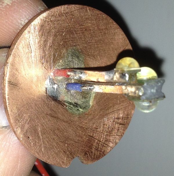
                    I have recently been experimenting with using power LED's to replace a conventional filament lamp in a parabolic reflector headlight. I wanted to run power to the small LED chips, which are SMD items, in a neat way with no major visible wires. What i used was very thin PCB material, bonded onto the main copper assembly.

                    Works pretty well, and is neat.

                    Comment

                    • KevinMc
                      Commander
                      • Feb 2009
                      • 305

                      #70
                      Hi Tom,

                      When reports start coming in that richter scales across the country have registered a sharp transient event don't be alarmed - that's just my forehead and my palm re-acquainting themselves. (I'm so embarrassed!) Andy is spot on about the different voltages dropped by different colours of LEDs. If you've got small buffering resistors in series, or if you've got colour/voltage matched LEDs you can string them in parallel through a common primary current limiter, but with colour mis-matched LEDs as you've got then a simple parallel circuit won't work - series resistors for each LED are your only option.

                      I'm sorry buddy! (And please extend that out to Sam as well!)
                      Kevin McLeod - Oscar II driver
                      KMc Designs

                      Comment

                      • trout
                        Admiral
                        • Jul 2011
                        • 3547

                        #71
                        Andy, that is very cool!

                        And Kevin, .....what can I say? You made one mistake in 2014, the new year is around the corner!
                        as it is unless I put in a small etched circuit and used SMD resistors, the room in that sail would have been too crowded. So all is forgiven and forgotten.
                        If you can cut, drill, saw, hit things and swear a lot, you're well on the way to building a working model sub.

                        Comment

                        • KevinMc
                          Commander
                          • Feb 2009
                          • 305

                          #72
                          What size resistors did you settle on for your LEDs?
                          Kevin McLeod - Oscar II driver
                          KMc Designs

                          Comment

                          • trout
                            Admiral
                            • Jul 2011
                            • 3547

                            #73
                            Only one resistor, 33 Ohm, it went on the Red LED because it was significantly brighter than the others. The other benefit was the green got a slight bit brighter when I did that and the red one was dimmed. They balanced out.
                            If you can cut, drill, saw, hit things and swear a lot, you're well on the way to building a working model sub.

                            Comment

                            • Subculture
                              Admiral
                              • Feb 2009
                              • 2126

                              #74
                              33 ohm sounds a bit low if you're running with a 6 volt bus. Small LED's like that shouldn't need more than about 10 milliamps, and certainly you don't want to be running them beyond 15-20mA if you want them to experience a long life.

                              50-100ohms would be a better choice for three or four LED's in parallel with a 2.5 volt drop.

                              Comment

                              • trout
                                Admiral
                                • Jul 2011
                                • 3547

                                #75
                                Yes, you are right Andy. When I was originally going to put a resistor to each one, I went ahead and soldered a 270 ohm for each of the colored ones and 100 ohm for the white. The colored ones were OK at 270, but the white one was WAY too bright when I tested it. Sam complained of not being able to see after I showed him (joking). So, I put a 540 in and it was then slightly brighter than the colored ones. That being the case, it became a logistical nightmare stuffing it all in the sail. So, when I did the mock up with a common resistor, I do not know if it is this cr***y solder or wire that were introducing their own resistance, but when I put any resistor in the common, they went dark. Without any resistor the red was the overly bright LED (after removing the white LED). The green and orange were looking about the same as with a resistor. So I put one 30 ohm resistor on the red and that was enough to bring it down. Then sealed it up. If they fry, well Sam can paint them and call it scale lights and kick anyone in the shin if they argue with him.
                                If you can cut, drill, saw, hit things and swear a lot, you're well on the way to building a working model sub.

                                Comment

                                Working...