Moebius (Revell) Skipjack Build

Collapse
X
 
  • Time
  • Show
Clear All
new posts

  • trout
    replied
    The big pieces of lead are placed in the sub. So a little was in the front and a bit of foam is in the rear. I moved some weight around and shaved off an ounce and a half of weight.
    Click image for larger version

Name:	Skipjack_build_245.jpg
Views:	1
Size:	98.4 KB
ID:	83735
    with it leveled off, it was still a little high in the water. Added 1/2 oz. back on the sub near the center of balance.
    Click image for larger version

Name:	Skipjack_build_246.jpg
Views:	1
Size:	85.9 KB
ID:	83736
    That was just enough to bring it to the top of the sail. I think that is a good spot.
    Click image for larger version

Name:	Skipjack_build_247.jpg
Views:	1
Size:	91.3 KB
ID:	83737
    That worked. It settled nicely.
    Click image for larger version

Name:	Skipjack_build_248.jpg
Views:	1
Size:	92.2 KB
ID:	83738
    The video is last, there is a reason.....and I blame Manfred.
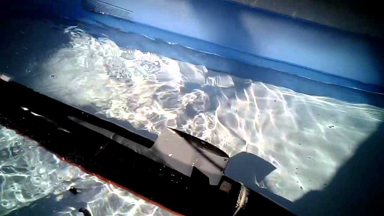
    Upon blowing out the ballast tank. Again the rear was very high. (and I bent the prop)
    Click image for larger version

Name:	Skipjack_build_249.jpg
Views:	1
Size:	85.0 KB
ID:	83739
    You can see that completely emptying the ballast tank the sub as a whole rises high.
    Click image for larger version

Name:	Skipjack_build_250.jpg
Views:	1
Size:	89.5 KB
ID:	83740
    I will need to complete the trimming in the solid walled test tank (tub)


    I will get that sound for you Manfred.

    Leave a comment:


  • alad61
    replied
    Looks good so far Tom and yep the s.a.s is brilliant. With the trimming don't over think it. Most of mine is on and just forward of it's cog with a bit of foam on the hull split. To get my aft level with a full ballast I added foam above the water line. Not the normal thing to do but it got it level. Can't wait to see your first run.

    Leave a comment:


  • MFR1964
    replied
    Yeah Tom, building subs stirs up the mind and brains, that's what i like the most, looking forward to see the vid, thanks for taking the effort.


    Manfred.

    Leave a comment:


  • trout
    replied
    Thanks again for the kind words and encouragement. I have not been able to get the sub in the water for trimming and filming. Yes Manfred, I will get some video for you. The RTV is drying on the screws in the ballast tank. I weighed all the lead used so far and it came out to 805 grams or 1.774 pounds. I am trying to get my head around how I will make the aft end balance out while surfaced. I love the way building subs challenges and makes you work for a solution.
    Last edited by trout; 10-10-2013, 02:58 AM.

    Leave a comment:


  • MFR1964
    replied
    Thanks for the link David, it will be most usefull in the future, you never know when i need strangely shaped magnets.

    Manfred.

    Leave a comment:


  • He Who Shall Not Be Named
    replied
    Originally posted by MFR1964
    That's slick!!

    Manfred.
    Take a bow, Tom!

    Here's our source of those and all sorts of other plated magnets:

    Gaussboys Super Magnets - Your source for high quality neodymium rare earth magnets. Custom shapes and sizes available. Now accepting bitcoin.


    M

    Leave a comment:


  • MFR1964
    replied
    That's slick!!

    Manfred.

    Leave a comment:


  • He Who Shall Not Be Named
    replied
    Originally posted by MFR1964
    Excellent Tom!, good to hear you like the SAS, it's the brainchild of a united effort on this forum, i only delivered my part to the system.
    Can you make a vid from your SAS adventure?, wanna hear her woooosh.
    As for connecting your SAS float, if i remembered right, you had designed a magnetic airconnector, i suppose you want to use this for easy handeling the SAS, great design!


    Manfred.
    Right you are, Manfred. In fact, Tom had sent me some samples of what he's worked up in the way of magnetically latched plumbing connectors, as well as a more robust version of our magnetic linkage connectors. Feast your eyes on his work here:

    Click image for larger version

Name:	028.jpg
Views:	1
Size:	89.1 KB
ID:	83672Click image for larger version

Name:	029.jpg
Views:	1
Size:	85.6 KB
ID:	83673Click image for larger version

Name:	032.jpg
Views:	2
Size:	83.5 KB
ID:	83674Click image for larger version

Name:	034.jpg
Views:	1
Size:	86.6 KB
ID:	83675Click image for larger version

Name:	035.jpg
Views:	1
Size:	86.3 KB
ID:	83676Click image for larger version

Name:	039.jpg
Views:	1
Size:	82.9 KB
ID:	83677

    Leave a comment:


  • MFR1964
    replied
    Excellent Tom!, good to hear you like the SAS, it's the brainchild of a united effort on this forum, i only delivered my part to the system.
    Can you make a vid from your SAS adventure?, wanna hear her woooosh.
    As for connecting your SAS float, if i remembered right, you had designed a magnetic airconnector, i suppose you want to use this for easy handeling the SAS, great design!


    Manfred.

    Leave a comment:


  • trout
    replied
    Tonight, I had to see what the Skipjack model looked like in the tub. Wow, the weight I made kept her in a upright position which is nice. There is nothing like the shock of putting a sub in the water and watch her unceremoniously flop on her side. I flooded the ballast tank and she settled aft heavy and bow would not go under. I grabbed some weight and placed it on the bow and the sub settled down to a level attitude. It may not stay that way once I get the sub in the kiddie pool because the tub may have been stopping the aft from sinking further.
    Then I emptied the ballast tank and it was cool to hear the suction noise when the float dropped allowing the air to come in. I did not completely empty the tank because I had plenty of reserve. On the surface the aft was light. I am using a single battery, but if it is heavy submerged and light surfaced, so I see it will take a bit of playing to get it right.
    Tried a little forward thrust while holding it......oh my goodness the power this puts out! Glad that it was dialed back to 50%, I might have lost my grip if it was 100% (pretty surprising the amount of power it generated).
    I also played a little more with the SAS system, thank you Manfred! You were instrumental in the design of this and it worked wonderfully.
    sorry about no pictures. It was just supposed to be a quick test and I got carried away playing. Possibly tomorrow!

    Leave a comment:


  • trout
    replied
    The weights needed to be made.
    Rolled out some potters clay. It was rehydrated, but a little too much. It was left for a day to ry out
    Click image for larger version

Name:	Skipjack_build_237.jpg
Views:	1
Size:	88.5 KB
ID:	83624Click image for larger version

Name:	Skipjack_build_238.jpg
Views:	1
Size:	88.3 KB
ID:	83625
    Once it was in a useable condition, I measured and trimmed the clay to fit. As a whim, I carved a message and info into the clay.
    Click image for larger version

Name:	Skipjack_build_239.jpg
Views:	1
Size:	91.6 KB
ID:	83628Click image for larger version

Name:	Skipjack_build_240.jpg
Views:	1
Size:	91.5 KB
ID:	83629
    Once dry, I put modeling clay in the base of a disposable plastic storage tub. Then stuck the clay pieces into the the modeling clay. I used plaster to fill the tub. I did not take pictures, but the process was once the plaster solidified, I dug out the modeling clay and soaked the plaster block in water. The potters clay will rehydrate and get soft again. Using a long toothpick or a bamboo skewer cleaned out the remaining clay.
    Click image for larger version

Name:	Skipjack_build_241.jpg
Views:	1
Size:	85.0 KB
ID:	83630
    I really rushed this last part. I put the plaster block in the oven on low for 4 hours (usually let it dry for a day or more). Melted some lead and poared in. Unfortunately the moisture cause steam and bubbling. There were no legible letters, but I had weights.
    Click image for larger version

Name:	Skipjack_build_242.jpg
Views:	1
Size:	89.2 KB
ID:	83631
    Tested the sub-driver in the tub. Everything stayed nice and dry. The only place that air bubbles showed up was from the side screw in the ballast tank. I will put a little RTV silicon in there.
    Click image for larger version

Name:	Skipjack_build_243.jpg
Views:	1
Size:	99.1 KB
ID:	83632Click image for larger version

Name:	Skipjack_build_244.jpg
Views:	1
Size:	89.9 KB
ID:	83633
    This is SOOOO cool! Played with the SAS. I am going to like this system and can not wait to get the sub trimmed out.
    Last edited by trout; 10-06-2013, 10:56 PM.

    Leave a comment:


  • trout
    replied
    David, I am also getting excited about seeing her run. This is a great setup and if someone is reading this thinking can I build a sub, I will say a resounding yes! First sub or one of many this is a joy to build. We are getting close.
    Finishing the hose connections.
    The sail connection gets a strain relief. In this case it is a larger diameter plastic tube.
    Click image for larger version

Name:	Skipjack_build_235.jpg
Views:	1
Size:	91.2 KB
ID:	83563
    The air hose will be cleaned up at a later time. I have a connector I made, that I will need to test with a SAS system.
    Click image for larger version

Name:	Skipjack_build_236.jpg
Views:	1
Size:	89.2 KB
ID:	83564

    Next step is get some weight installed.
    Last edited by trout; 10-03-2013, 10:48 PM.

    Leave a comment:


  • He Who Shall Not Be Named
    replied
    Yeah, I provide the motor-bulkhead manifold for those using this in the other 1/72 scale boats that are not as tight in the ass-end as the SKIPJACK. Sorry about that, Tom.

    Can't wait to see this guy in the water.

    David

    Leave a comment:


  • trout
    replied
    David that is encouraging that you like the WIP. It means a lot coming from you. A heads up earlier to not install it would have been better :-), but the information is out there for someone else not to mount the SAS manifold. I make mistakes and I post them (well mostly, I didn't post about the wind knocking my sail off the table and crud stuck to the sail or that periscope box was slightly too big because I assembled it with the fore and aft walls on the outside instead of the inside plus that latch - correctable, but would be a time consuming thing that I will fix later) Which is why I recommend waiting until she gets her maiden voyage before following what I did.
    Taking the manifold off was not a big deal, it took a careful prying it away. I love RTV silicon, especially this blue stuff. I took some Acetone and carefully cleaned the surfaces and then picked, pull, scr@ped the rubber off.
    Click image for larger version

Name:	Skipjack_build_233.jpg
Views:	1
Size:	87.8 KB
ID:	83560
    Cleaned the sail pushrod off and realigned it (applied some CA, slid it on, then sealed the hull and moved the sail plane until it engaged. Let the CA solidify. Ran one hose (the other one will go on later after the pushrod connection dries completely).
    Click image for larger version

Name:	Skipjack_build_234.jpg
Views:	1
Size:	92.1 KB
ID:	83561
    Just cannot think my fat fingers pulling the hoses off these nipples will not eventually knock something else off. I might need to build a couple of connectors to make the process easier, but again the motto get it running first than add do-dads comes to mind.
    I know this is a short posting. Life happens. That being said, I try to get one thing done on the sub each day.

    Leave a comment:


  • He Who Shall Not Be Named
    replied
    Hey, fumble-thumbs:

    You'll find that you can't use the motor-bulkhead SAS manifold -- it sticks up too high and will hit the upper hull when you attempt to push it down in place. Don't use the manifold, rather run the flexible hoses straight to the induction and discharge nipples.

    I'm enjoying this WIP, Tom. Good stuff.

    M

    Leave a comment:

Working...