I supplied the 'dumb-bell' with the 1/72 SKIPJACK SD for a reason, guys!
M
-
I supplied the 'dumb-bell' with the 1/72 SKIPJACK SD for a reason, guys!
MLeave a comment:
-
I think it was on the Gato cylinder that David supplied a "Bellcrank" mechanism, if I remember correctly that we might be able to acquire for that situation. If not we could make our own, it just wouldnt be as pretty as Daves.....Im thinking.Leave a comment:
-
Agreed. Mark, that magnet I put a brass tab on it and it stays put. It is the aft connector where the issues are happening.Leave a comment:
-
I was thinking that the magnetic connection at the sail plane itself is unnecessary since the magnet is to make it easier to disconnect and connect during setup. That connection doesnt need to come apart or together for setup. If we eliminate that then there is one less problem. I was thinking about taking the magnet out and putting a small short screw in it and attach a clevis like you get at a hobby store and attach that to your rod or cable. Also, I dont have mine to that point yet but the sail plane pushrod, the way it exits the Subdriver, bends 90 degrees and then bends another 90 degrees can give a lot of "Flex" that might not be good.Leave a comment:
-
Tested the rudder and the beefier connectors solved that issue. The sail plane is another story. There are two variables from when it was working, one the drop and two the sail linkages were disassembled when it was painted. So somewhere in there it is not happy. I can get it to connect, I can feel it connect and for a short time work, but if I go hard in either direction it seems to disconnect or lose the control of the plane. Then I thought maybe I have too much throw and that is causing it to disconnect. Been playing with that. Still nothing consistent.
I may have to redo the sail connectors so that they meet under the hatch. Then open the hatch up so I can see the connection. I do not like working blind.
So I will sleep on it and try again tomorrow. Any suggestions?Leave a comment:
-
Finished by putting a tube between the float valve and the reservoir.
I matched the float valve's tube leaving the top with the tube going into the reservoir. They are 3/32", but the grey hose id seems to be 3/32" so the fit is not tight. I put RTV to seal it, not confident it will hold. If it does not I will put a 1/8" od tube over the nipple of the float valve and the stem of the reservoir.
Since I had the RTV silicon out and had some left over, I smeared some over the center plug that David said could leak.
Next is the rudder disconnecting issue. For that I put on the heavier duty connectors, but I have another idea using the existing Klik-ons that I will put down as a future project.
Last thing on my repair list is the sail plane. I put this off because I do not have a clear idea how or what to fix for sure.Leave a comment:
-
Thanks Alec for the confirmation and knowing we have the same issues.
Today there was not the time to get out to the water, but I did re-think the water reclamation system. It was tiny and would not hold a lot of water. The plumbing to get it to the bottom of the sub-driver did not appeal to me. So, plan two.
I created a lopsided pyramid, with one side being at 90 degrees. No, that is not accurate, it is a triangular slope. Oh here are some pictures, you tell me.
The 90 degree side faces outward and the slope side goes up against the motor.
On one end of the brass tube, two scalloped edges were put in. Opposite each other. The thinking is the rush of air/water coming in, I wanted it directed sideways. The other end of the tube was rounded.
Here is a test fit with the hole for the tube drilled in.
Made a quick drill guide for locating the vent hole.
Put the vent/overflow hole in.
Sealed the reservoir with RTV silicon rubber.
Now it is time to let it dry.Leave a comment:
-
Tom I can confir re the quick movements causing the float to shift letting water in the system. The first days sailing at the regatta I recently went to saw the skipjack porpoising and doing very sharp banking turns like a jet fighter. Both of which I handled badly on the tx and I believe these greatly contributed to water in the rear compartment. Once I dialed back the speed as David suggested and feathered my tx commands with better control the water issue was virtually nullified. Yes there will be droplets above the sas internal safety valve which I believe comes from water droplets being drawn in when the boat surfaces and the snorkel float falls away. Every now and then I have the rudder klick-ons disengage which only happens when I do an emergency all back on the throttle. I am seriously contemplating Marks double klick-on system for that. But I also like your glued in guide too. I have been driving my boat for many months and voyages now with great enjoyment but it can be a rocket if the speed is up over the 50 - 55% mark. I know this because even at 80 - 90% on the epa I generally had the throttle stick at ahead two thirds. Also throttle back a bit when turning. It helps eliminate the banking effect. Also whilst turning is when the sail planes show there value at keeping the keel level.
That said I like the flexible tube idea to suck back any water in the rear dry space something I might have a go at that...Leave a comment:
-
I so appreciate a thorough postmortem followed by a reasoned course of corrective actions presented in a WIP. So many guys just post the pretty pictures with little or no critical comments and fixes. Thank you, Tom, for using the sharp knife. Smiley-faces do me no good; pointed observations followed by informed analysis is what I need!
You deliver!
I like that moisture separator you came up with. A neat idea. But would it not be simpler (as you pointed out as an alternative) to simply run a flexible hose down from the safety float-valve nipple to the bottom of the dry space? That way you not only strip away any water that got past the valve during the next 'blow from depth' evolution, you also scavenge out any water that got into the after dry space from another route.
Early production bulkheads feature an installed plug in the center of the forward ballast bulkhead and forward bulkhead -- these were secured with CA and sometimes leak. Check those as possible routes of water intrusion into your forward space, Tom.
Well done, sir!
MLeave a comment:
-
Alec, Sam wants me to get a 1/72 Typhoon (because of Hunt for Red October), so someday that battle might occur. :-)
Post Mission Check
Not everything is perfect with the sub, not horrible either.
The engine room had water in it about a tablespoon. When I took the hull apart there were water droplets over the SAS float valve. I am going to assume it was from some of the snap turns I did as I got used to sailing the sub. On more than one time it banked pretty hard. Those could have jarred the sail's float seal enough to let the water in.
How to prevent it? not sure I can, but I can try to manage the water coming in. Since the SAS draws air from the inside of the sub-driver to expel the water in the ballast tank, I am thinking of using that to purge out some of the excess water. I could take a hose and run that from the nipple on the float tank to the bottom of the wtc to a tank that would collect water that comes in and vacuum water out. I chose to build a tray to hold water.
Here is a crayon drawing to help visualize what I think may work:
As water comes in, it will settled to the bottom of the tray and once the order to blow the tanks is given, the suction will draw the water out of the tray and expel it into the ballast tank.
Here is the tray installed.
Next, I had water in the battery compartment (maybe a teaspoon). It had been dry in my other tests, so something was marginally working, but failed with the additional depth. There are only 3 ways water is getting in. That would be from the o-rings, the switch, or the power conduit going between the bulkheads through the ballast tank.
A visual looking over the end cap, I did not see any clues.
Even the bulkhead conduit looked O.K. On the Gato I sealed the tube with RTV rubber, I may do that here too.
Next I inspected the o-ring seal on the bulkheads and end caps.
You can see in the above photo the area being squished against the polycarbonate tube, it is a dark black line.
Rotating the end cap I found this:
A small piece of o-ring was damaged and a sliver of the rubber is torn. And near it is a gap where no contact is happening between the tube and o-ring. This will need to be replaced even if the leak is not coming in from here. I will run the sub again and see if water is in there again.
The sail plane magnet was tweaked, probably from the pull off the counter top. The aluminum tube in the upper hull was also bent.
I did not get a chance to work on the sail connecting issue.
The last issue I had was the rudder and making a hard port turn. It would get stuck enough that the Klik-on did disengage and did not have enough pull to reengage even with the bracket holding it. At the poolside I wrapped a rubber band between the magnets and that solved the problem temporarily.
Tomorrow Sam is walking with his Scouts in the Veteran's Day parade. If there is time, I will try to get the sub in the water again.Leave a comment:
-
Nice video and manoeuvring Tom. All it needs is a Russian bogie sub in the shadows and some torpedos skimming past for that Hollywood Cold War epic...
Once you get the sail planes working you'll hardly ever need totouch the rear planes.Leave a comment:
-
I will not be able to throw enough adjectives to describe how amazingly fun this sub was to drive.
At the pool I could not get my sail plane to engage. So I thought I would just see what I could do with the sub. I don't need no stink'n sail plane! Using speed and leveler adjustments I had a blast.
So much so that I did not take one picture. The only footage taken was by Sam while swimming in the pool. So pardon the shaky footage, but here you go:
Leave a comment:
-
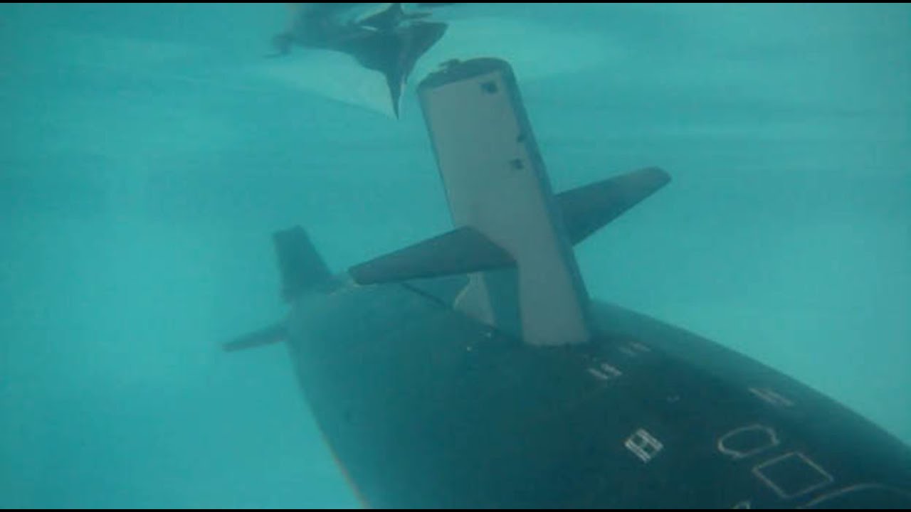
Yes it was stressful, but it was amazing! This sub is fantastic! What a great system David put together! This test was done in a pool (and a recently repaired one - hence the cloudy conditions), more to report later with video.
Right now here are some teaser photos from the video:
Leave a comment:
Leave a comment: