Welcome to our forums. For the best in R/C submarine kits, components and accessories, be sure to visit the Nautilus Drydocks
If this is your first visit, be sure to
check out the FAQ by clicking the
link above. You may have to register
before you can post: click the register link above to proceed. To start viewing messages,
select the forum that you want to visit from the selection below.
That would be great! Thanks. The SD came with a bunch of extra connectors that I presume is for the LPB. From your photos it appears that you are using the LPB so any images of that would also help.
Just acquired a Revell Type VII myself. Also got the fittings kit.
No dedicated SD or WTC yet but I do have a Seawolf SD unit. Was thinking of using it in the Type VII, would it work? The Seawolf is a single prop while the u boat has 2 so I definitely need to fabricate a geartrain. ( could just drive of the screws as what's often done on real boats). Can the ballast tank volume be enough to support the type VII?
I'm building a VIIC too. The SD came with manifold blocks that look like they adapt to SAS, although I have a tank installed and no float or safety valve apparatus. The middle block now has the induction pipe from sail coming in parallel to the lexan tube, and there is a third manifold block which is simply a right angle turn block which I guess goes somewhere near front of SD(?).
In all of this I'd like to be able to use either tank or SAS, so if there is any positioning of something or addition of something (such as putting a hole in deck under sail such that it won't interfere with the float valve later on) could you state so. And I have the following questions:
1) where do I place the two manifold blocks middle and front(?), ...I'd like to use tank with SAS if desired later- this may make placement of middle manifold block tricky, or at least demand a precise positioning under the sail? About how many inches behind the gas tank valve centerline should I drill the hole in the lexan and mount the middle block?
2) Where does the front block go and what purpose does it serve?
3) I have all the larger upper limber holes cut. Are there some holes I should not cut lower down to avoid weakening the plastic?
4) As observed by OP there is no velcro band supplied. But there is also no indexing pin/hole supplied. How do I position or line up the SD within the hull?
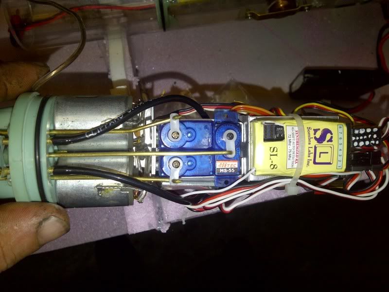
5) What is the 4th "connecting rod" port in aft bulkhead for? The one with a short brass L-shaped rod stuck in it? It has the same seal as the other three ports, but is just below them and in between motors?
Update: Just got done testing the gas/vent valve, all is well there. Had to tighten the tank fill nipple valve, quick tweak. Looks really great, look forward to having three ways to blow! Please let me know about these questions as some are puzzling and others critical to positioning of both SAS and Gas. Thank you again.
Last edited by H2Ohaze; 07-03-2012, 09:05 PM.
Reason: added update
Along with the lack of info regarding the indexing pin there's also the matter of the absence of the SD unit support saddles. Does one use the kit's existing bulkheads as with the Gato conversion?
1) I am still new to all of this and in the learning stage. The three "manifolds" I believe are for the SNORT system (an optional purchased air pump to drain the ballast of water once the periscope breaks surface (assuming the intake tube is there). Those manifolds redirect the intake to the pump then back out to the ballast tank. In the ballast tank should be a a small copper tank that is charged with air and used as either a primary of backup system to empty the ballast tank of water. I still am not sure of the exact placement and I will soon be corrected by David, but I think the one with the two parallel tubes goes on the stern bulkhead to direct the air tubes forward. The next manifold has two tubes on one side, one tube opposite and an hole on the bottom. This should get placed over a hole on top of the lexan tube over the ballast portion to allow air from the pump to fill the ballast. The other in/out brass tube is for the air intake and just connects the tubing to the third manifold. The third manifold consisting of a single 90 degree tube is the air intake which directs the intake tube through the periscope.
2) Not sure what you are referring to, bu I also got a small angular block with three dimples on each side. I don't know what that is for.
3) I cut the upper limper holes, all the holes around the forward planes, most of the hole around the bow (series of 12 round holes and three oval on each side above the torpedo doors), Five oval holes on each of the stern tubes, the stern torpedo tube is open per the fitting kit, and I have three 1/4" holes on the bottom where the rectangular plates are mid-ship. I couldn't cut them in the rectangular shape.
4) Once I get back my SD (went in for repairs), I will position the it figure out where the SNORT tubes and manifolds should go, make a mount for the tube including the index pin and strap. This is all depended on seeing where the SD lies when I add the dog-bone collars.
5) The fourth connecting rod serves no purpose for this sub. I guess the rear bulkhead was designed for several subs and easier to make them one way to be adaptable or perhaps for use of a rear torpedo tube system. That is my guess.
There is a really good PDF on this site regarding the Seaview which describes very well the SD and all of its components. Took me a while to find it, but very useful. http://support.caswellplating.com/in...r-instructions
David or anyone else, please correct me if I am wrong in the above.
On question one I'm sure on what the rear and middle manifolds are and do. I just don't know where to place the 2nd one wrt a reference on the SD tube, so that BOTH Gas and SAS can both be used. There is no pre-drilled hole to fill tank from above.
The first "right angle" manifold I have seen in a Gazette picture placed way up front. Here, it can't be used to go up to the float tube or induction tube, since it's right below the VIIC deck- no room. This is what I refer to in question #2...where does it go and what does it do? The right angle manifold. This ties in with placement of the SAS safety valve- a small brass can that because of space will have to sit outside of the VIIC SD...either in front or behind (if it fits with all the rods and shafts).
Now if the safety canister goes in front, that first right angle manifold might come in very handy, but I don't have the logic in my mind straightened out as to whether it sticks on up front or next to the middle manifold or ...? And orientation. A wild guess is a line goes from the middle manifold towards the front, then connects to safety canister and T connection, then runs back to middle of SD where the first right angle manifold (is glued) directs it up right under the sail to the float valve.
The block you refer to I believe may have something to do with SAS float install, but whatever it is, that was not my question. It is a good question though...?
In question 5, if the connection is not used in this sub but in others, why doesn't Caswell just not install the seal and glue hole closed? Or at least pull the rod out and jam some RTV in the seal hole. One less seal in a bulkhead to worry about.
Thanks for the link. I've already pulled down a lot of pdfs from the site, but not that one.
I think the one BIG comprehensive question I have is: how do I put together with careful enough alignment/placement to allow for both Gas and future SAS? Pics optional, but nice.
Sorry if I sound cranky, the Colorado fires have a lot of smoke in the air and everyone is like this.
Along with the lack of info regarding the indexing pin there's also the matter of the absence of the SD unit support saddles. Does one use the kit's existing bulkheads as with the Gato conversion?
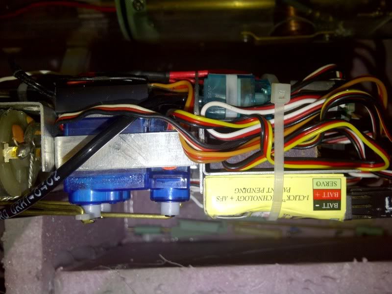
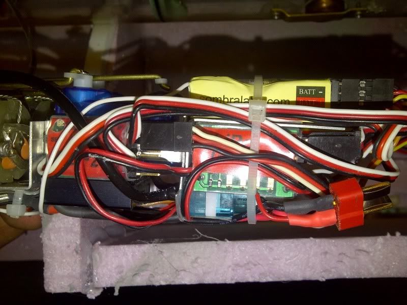
no saddles or bulkheads.. the SD barely squeezes in... basically setup the driveshafts, line up the SD with dogbones ... this is your SD's new home...
then pick a spot for the indexing pin in the bottom of the hull... in a spot that coresponds with a spot you can safely drill a hole (or 4) in the SD ... aka bottom of the ballast tank..
took me 4 holes from where I initially indexed my SD ... then velco strips over top to tie it down inplace.
Avera, that pdf for the Seaview answers a lot of questions- glad you found it!
Okay, the extra port in the back is just that- leave it alone...
And also from pdf and Reckless you rig up your own pin where and how you want. But can't be done until dogbones are in place. I'm putting the cart before the horse.
I suspect placement of the second manifold and top entrance hole from LPB the same way- wait until everything else in place. It would be nice to have the extra SAS stuff by then, to decide on a good compromise using both GAS and SAS for sail placement of tube going down to 2nd manifold.
Still a puzzle exactly how the right angle manifold and that block with partially drilled holes in it does or goes.
That one with the 'partially drilled holes' is a strain-relief block that goes into the forward dry space and is CA'ed to the inboard face of the forward bulkhead (removable cap).
Let's have a picture of the 'mystery' LPB manifold.
On a side note regarding the trim foam, any thought on the grey plumbing foam used to insulate pipes? The form comes in a split tube 6 feet long by 4.5 inches wide and about 3/8 inch thick. It appears closed cell (nearly as dense as neoprene but lighter) and does not retain water. Giving its curved shape, it should easily conform to the hull. My LHS does not carry any of the pink foam, nor does the local craft store.


Comment